

Page 1
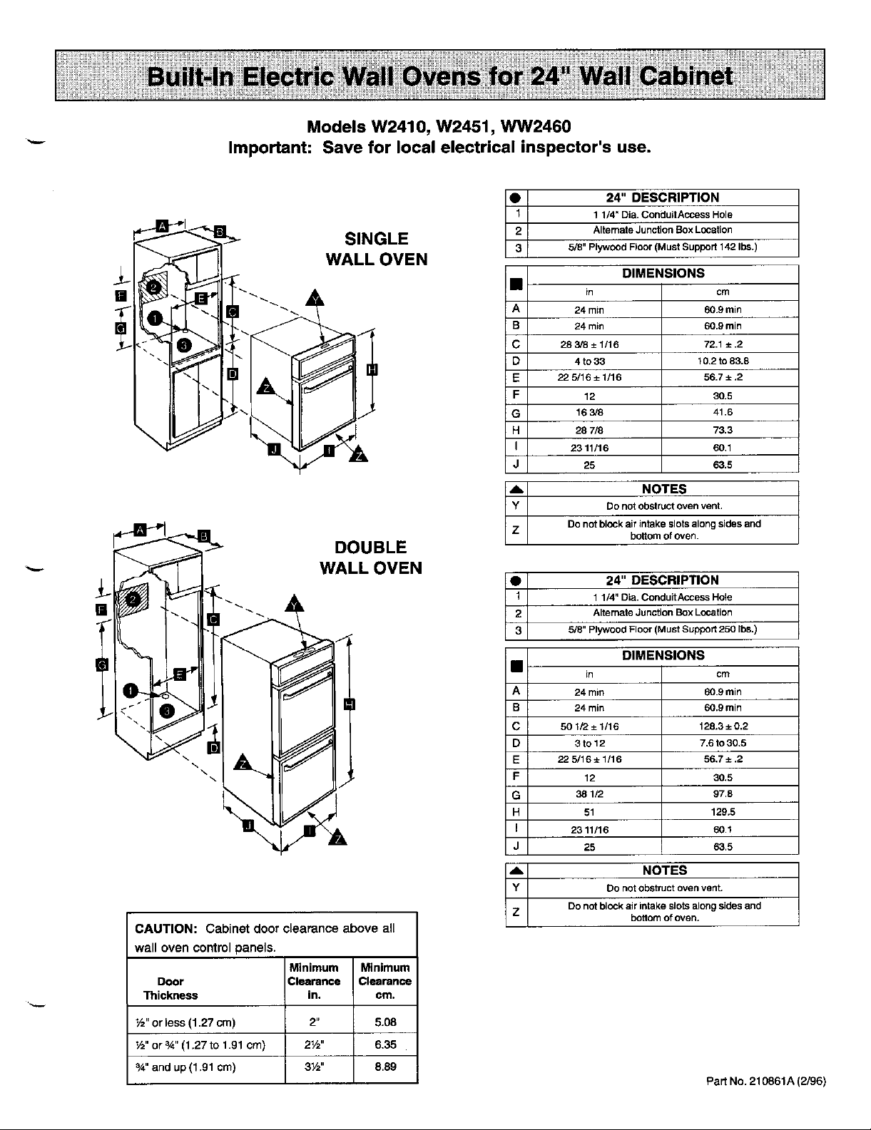
Models W2410, W2451, WW2460
"-" Important: Save for local electrical inspector's use.
O1 24" DESCRIPTION
S
INGLE 3 5/8"PlywoodFloor(MustSuppod142Ibs.)
2 AlternateJunctionBoxLocation
w...ow. ! o-s.o.
B 24rain 60.9rain
C 283/8±1/16 72.1±.2
i D 4 to33 10.2to83.8
E 225/16±1/16 56.7±.2
F 12 90.5
G 163/8 41.6
H 28 7/8 73.3
I 2311/16 60.1
J 25 63.5
A NOTES
Y Donotobstructovenvent.
Z Donot blockairintakeslotsalongsidesand
11/4' DiM.ConduitAccessHole
24 rain 60.9min
bottomofoven.
DOUBLE
WALL OVEN
• 24" DESCRIPTION
1 11/4"DiM.ConduitAccessHole
[] 2 AlternateJunctionBoxLocation
3 5/8" PlywoodFloor(MustSupport250 Ibs.)
J B 24 min 60.9min
CAUTION: Cabinet door clearance above all
wall oven control panels.
Minimum Minimum
Door Clearance Clearance
Thickness in. cm.
½" or less (1.27 cm) 2" 5.08
½" or _" (1.27 to 1.91 crn) 2_/2" 6,35
3/4"and up (1.91 cm) 3½" 8.89
DIMENSIONS
in cm
A 24 rain 60.9rain
C 50 1/2 ± 1/16 128.3± 0,2
D 3to12 7.6 to 30,5
E 225/16±1/'16 56,7±,2
F 12 30.5
G 38 1/2 97,8
H 51 129.5
I 2311/16 60.1
J 25 63.5
,_, NOTES
Y Do notobstructovenvent.
Z Donotblockair intakeslotsalongsidesand
bottomof oven.
Part No. 210861A (2/96)
Page 2

1, Cut hole in cabinet to mount oven. Cutout in cabinet should be level and straight. Note: There are no provisions to level
the unit after it is installed, An oven that is not level could cause poor baking results,
2. Install plywood floor as shown.
3. Attach unit to the cabinet with four No, 8 x 1" screws supplied with unit (inside of envelope containing these instructions),
Pre-drill holes in cabinet for attachment screws using 1/8" drill, Oven mounting holes are in each corner of front panel,
4. See instructions below for electrical hookup.
5. See User's Manual for operating instructions.
6. Single Wall Ovens are also U.L. listed to be installed as a combination unitusing Microwave Models M168 or M169 with
Trim Kit MK24, install per instructions packed with Trim Kits.
Installing Bottom Trim Piece
Wall Ovenwith Black or White Lower Trim
Packed with this unit is an additional bottom trim to cover the bottom edge of the unit front cutout, Secure trim and bottom
edge of unit front to cabinet using screws provided,
OVEN
i_ DOOR
================= FRONT
_==c:_c=__:_m c==_ _ == _ _ c=__ _==3_ c::::_c_ TRIM
Electrical Connections
Unit to be properly circuit protected and wired according to local electrical code and National Electrical Code.
It is advisable that the electrical wiring and hookup be accomplished by a competent electrician,
120/240 VAC or 120/208 VAC 60 Hz. See serial plate on front of unit for power requirements.
The neutral of this units grounded to the frame through the green or solid grounding wire. (The green and the white wires are
twisted together at the termination of the conduit.) If local conditions do not permit grounding of the neutral, untwist the green
wire and connect the green wire to ground in accordance with local codes. Connect the white neutral to the service neutral.
The chart below recommends the minimum circuit protection and wire size if the appliance is the only unit on the circuit.
Recommended Minimum
K.W.RATING CIRCUITPROTECTION WIRE SIZE,
ON SERIALPLATE INAMPRES AWG
0 - 4.8 20 12
4.9 - 6.9 30 10
7.0 - 9.9 40 8
10.0 - 11.9 50 8
12.0 - 14.9 60 6
Service
interrupt the source of electricity to the unit when attempting to repair or service the oven, Failure to do this could result in
a dangerous or even fatal shock.
Page 3

11-2e-1994 11 : 18 31"7 546 32?3 JENN-A I R D I SCOVERY CENTER P, {}3
C_'r_,UTION:For European style cabinets (flush front) the requiredclearancefor operation of the oven door is a minimum
spacingof7/8" betweenthecutoutendthe door,hingeor drawerof thecabinet.
Some built-incabinetsmaynot be wideenough,duetotheirconstruction,toallowthisInstallation.
1. Cut hole in cabinet to mount oven. Cutout in cabinet should be level and straight.NOTE: There are no
provisionstOlevelthe unitafterIt Is ins_lled,Anoventhat isnot levelcouldcausepoorbakingresults.
2, Installplywoodflooras shownabove.
3. Aftach unit to the cabinet with four No, 8 x 1"screwssuppliedwith unitInsideof envelopecontaining these
Instructions.Pra-drlgholes In cabinetforattachmentscrewsusing1/8" drill.Oven mountingholesare in each
corner of front panel. For combination units, install trimaround microwavewith four No. 6 x 1/2" screws
suppliedwith unit.Pre-drlUholes incabinetforattachmentscrewsusing3/32" drill,
4, See instructionsbelowforelectrical hook-up;
5. See User'sManualforoperatingInstructions.
8. SingleWallOvens are also U.L. ListedtObe installedas a combinationunitusingMicrowaveModelsM166 or
M167withTrimKitsA526, A530 or A424. InstallperinstructionspeckedwithTrim Kits.
INSTALLING BOI-I'OM TRIM PIECE
WALL OVENSWITHSLACKORWHITELOWERTRIM
Packed with thisunitisan additionalbottomtrimtocoverthebottomedgeofthe unitfrontcutout.
Securetrimand bottomedge of fronttocabinetusingscrews provided.
_fl pOVEN
_DOOR
I I AI __UNn"
ELECTRICALCONNECTIONS
r
Unit to be properlycircu!tprotectedandwired accordingto localelectricalcodeandNationalElectricalCode.
ItIsad_e thatthee_ectdcalwiringand hookupbeaccomplishedby• c_tent electrician,
1201240VAC or120/208VAC 60 Hz. Sea serial plateonfrontof unitforpowerrequirements.
The neutralof this unit is groundedto the frame throughthegreen or eclld groundingwire. (The greenand the whitewiresare
twistedtogetherat the terminationof the conduit.)If localconditionsdo not permitgroundingof the neutral,untwistthe green
wireand connectthe green wireto groundInaccordancewithlocalcodes.Connectthewhiteneutraltothe serviceneutral.
Thechert belowrecommendsthe minimumcircuitprotectionandwiresize ifthe applianceIsthe only unttonthe circuit.
RECOMMENDED MINIMUM
ILW. RATING FUSE SIZE WIRE SIZE,
ON SERIAL PLATE IN AMPERES AWG
0- 4.8 2O 12
4.g- 6,9 30 10
7.0- 9,9 40 8
10.0 , 11.9 50 8
12.0 - 14.9 60 6
SERVICE: _......
Interruptthe source of electricitytothe unitwhenattemptingto repairorservicetheoven,Failuretodo thiscouldresult
ina dangerousor even fatalshock.
 Loading...