

INSTRUCTION SHEET FOR DISHWASHER
NOIR™ HANDLE ACCESSORY
BEFORE YOU BEGIN:
The handle and handle mounting hardware must be installed
before installing the custom panel.
IMPORTANT:
■ This kit is designed to be used only with wood panels.
■ To avoid damage, lift the panel assembly by the edges.
■ A customer supplied door panel and handle (together) shall
weigh no more than 14.7 lbs (6.7 kg).
■ To ensure the optimum door balance performance, these
are the maximum weight for components:
Custom wood panel - 10.5 lbs (4.8 kg).
NOIR™ handle - 4.2 lbs (1.9 kg).
TOOLS NEEDED:
Gather the required tools and parts before starting installation.
Read and follow the instruction provided with any tools listed
here.
■ Cordless drill ■ Tape measure
■ 3/16" Twist wood
■ Pencil
drill bit
■ Hexagonal 5/16"
■ 5/8" Flat wood drill bit
nut driver
PARTS SUPPLIED:
■ Handle ■ Screws - #10-24 x 1" Hex head
■ Washer ■ Nut - #10-24"
1. Measure from the center of the custom panel and mark the
holes location as shown in Figure 1
NOTE:
■ The custom panel should have a thickness of 3/4"
(19.05 mm).
1
■ 3
/8" (80.1 mm) from the top of the panel is the
recommended mounting location. Measurements
from the top edge of the panel will depend on specic
application and panel design.
2. Drill 3/16" (4.76 mm) diameter holes at marked locations
(refer Figure 1).
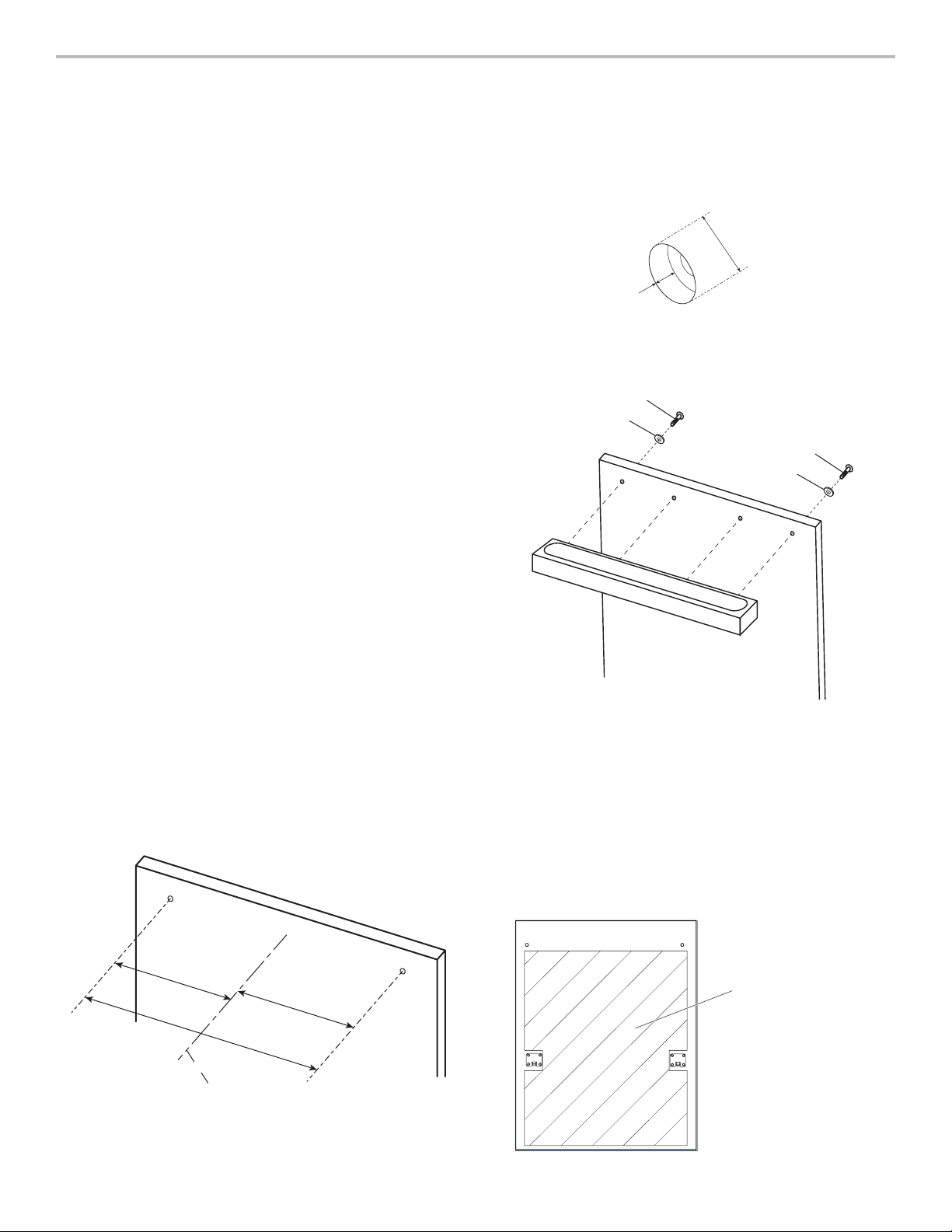
3. Countersink the two holes near the ends of the panel on the
back of the panel, 5/16" (7.9 mm) deep and 5/8" (15.8 mm)
diameter for screw head clearance (refer Figure 2).
5/8"
(15.8 mm)
5/16"
(7.9 mm)
Figure 2
4. Install handle to front panel with screws and nuts (refer
Figure 3).
Screw - #10-24 x 1"
Washer
Screw - #10-24 x 1"
Washer
Figure 3
5. If needed, adjust the spring tension. Check the dish product
manual to nd out how to make this adjustment.
6. If necessary, wood can be removed from the back side of the
panel (see picture) to meet maximum weight specication.
Removal of material from the top portion of the panel will
help achieve optimum door balance performance.
“The wood can be removed by power tools suitable for this
function such as the Electric Planer”.
IMPORTANT - Do not remove wood from the parts where the
clamps and the handle are screwed.
103/16"
(258 mm)
205/16"
516 mm
Center of
panel
Figure 1
103/16"
(258 mm)
Area where it is possible to
remove wood to reduce weight
FICHE D’INSTRUCTIONS POUR POIGNÉE DE
LAVE-VAISSELLE NOIR
TM
AVANT DE COMMENCER:
La poignée et les pièces de montage de la poignée doivent être
installées avant d’installer le panneau personnalisé.
IMPORTANT:
■ Cet ensemble est conçu pour être utilisé avec des panneaux
de bois.
■ Pour éviter les dommages, soulever le panneau par les bords.
■ Une poignée et un panneau de porte fournis par le client ne
devraient pas peser plus de 14,7 lbs (6,7 kg).
■ Pour assurer l’équilibre optimal de la porte, le poids
maximal des composantes ne devrait pas dépasser :
Panneau de bois personnalisé – 10,5 lbs (4,8 kg).
Poignée NOIR™ – 4,2 lbs (1,9 kg).
OUTILS REQUIS:
Rassembler les outils et pièces nécessaires avant d’entreprendre
l’installation. Lire et observer les instructions fournies avec
chacun des outils de la liste suivante.
■ Perceuse sans l ■ Ruban à mesurer
■ Forets ■ Crayon
■ Foret hélicoïdal de 3/16 po
pour le bois
■ Foret à langue d’aspic de
5/8 po pour le bois
PIÈCES FOURNIES:
■ Poignée ■ Vis à tête hexagonale – no10-24 x 1po
■ Rondelle ■ Écrous – no10-24 po
1. Mesurer la distance au centre du panneau personnalisé
et marquer l’emplacement des trous comme indiqué à
l’illustration1.
REMARQUE:
■ Le panneau personnalisé devrait avoir une épaisseur de
3/4 po (19,05mm).
■ La position d’installation recommandée est à 3
(80,1mm) à partir du haut du panneau. Les mesures
à partir du bord supérieur du panneau dépendent de
l’application et de la conception du panneau.
2. Percer des trous de 3/16 po (4,76mm) aux endroits marqués
(consulter l’illustration1).
1
/8 po
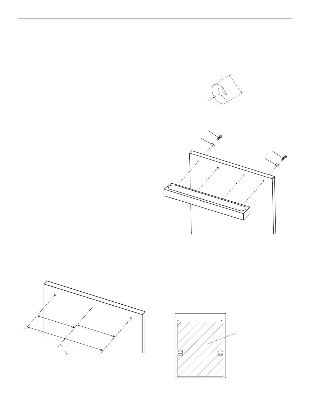
3. Fraiser les deux trous près des bouts (à l’arrière du panneau)
d’une profondeur de 5/16 po (7,9 mm) et d’un diamètre de
5/8 po (15,8 mm) pour la distance de séparation de la tête de
vis (consulter l’illustration 2).
5/8 po
(15,8mm)
5/16 po
(7,9mm)
Illustration2
4. Installer la poignée à l’avant du panneau en utilisant les vis et
écrous, consulter l’illustration3.
Vis – no10-24 X 1po
Rondelle
Vis – no10-24 X 1po
Rondelle
Illustration3
5. Au besoin, régler la tension du ressort. Vérier le manuel
d’utilisation du plat pour savoir comment effectuer ce
réglage.
6. Si nécessaire, le bois peut être retiré de l’arrière du panneau
(voir illustration) pour respecter la spécication du poids
maximum. La suppression de matériau dans la partie
supérieure du panneau permettra de garantir l’équilibre
optimal. “Le bois peut être enlevé avec un outil électrique
conçu pour cette fonction, p. ex., un rabot électrique”.
IMPORTANT - Ne pas enlever le bois des parties où il est
nécessaire de visser les attaches et la poignée.
10 3/16 po
(258 mm)
10 3/16 po
20 5/16 po
516mm
Centre du
panneau
(258 mm)
Zone où il est possible de retirer
le bois pour réduire le poids
Illustration1
W11294385D 04/19
®
/™ ©2019 JennAir. All rights reserved. Used under license in Canada.
Tous droits réservés. Utilisé sous licence au Canada.
 Loading...