

Page 1
30" (76.2 CM) AND 36" (91.4 CM) GAS DOWNDRAFT
You can be killed or seriously injured if you don't immediately
You
can be killed or seriously injured if you don't
follow
All safety messages will tell you what the potential hazard is, tell you how to reduce the chance of injury, and tell you what can
happen if the instructions are not followed.
Your safety and the safety of others are very important.
We have provided many important safety messages in this manual and on your appliance. Always read and obey all safety
messages.
This is the safety alert symbol.
This symbol alerts you to potential hazards that can kill or hurt you and others.
All safety messages will follow the safety alert symbol and either the word “DANGER” or “WARNING.”
These words mean:
follow instructions.
instructions.
DANGER
WARNING
IMPORTANT:
Installer: Leave installation instructions with the homeowner.
Homeowner: Keep installation instructions for future reference.
IMPORTANT :
Installateur : Remettre les instructions d'installation au propriétaire.
Propriétaire : Conserver les instructions d'installation pour référence ultérieure.
COOKTOP INSTALLATION INSTRUCTIONS
INSTRUCTIONS D'INSTALLATION DE LA TABLE DE
CUISSON À GAZ À ASPIRATION PAR LE BAS
DE 30" (76,2 CM) ET DE 36" (91,4 CM)
Table of Contents/Table des matières
COOKTOP SAFETY........................................................................1
INSTALLATION REQUIREMENTS ................................................3
Tools and Parts ............................................................................3
Location Requirements ................................................................3
Venting Requirements..................................................................5
Venting Methods ..........................................................................6
Electrical Requirements ...............................................................7
Gas Supply Requirements ...........................................................8
INSTALLATION INSTRUCTIONS ..................................................9
Install Cooktop .............................................................................9
Rotate Blower - Optional..............................................................9
Make Gas Connection................................................................10
Electronic Ignition System..........................................................12
Complete Installation..................................................................12
COOKTOP SAFETY
SÉCURITÉ DE LA TABLE DE CUISSON .................................13
EXIGENCES D'INSTALLATION................................................14
Outillage et pièces...................................................................14
Exigences d'emplacement......................................................14
Exigences concernant l'évacuation ........................................16
Méthodes d'évacuation...........................................................17
Spécifications électriques .......................................................19
Spécifications de l'alimentation en gaz ..................................19
INSTRUCTIONS D’INSTALLATION .........................................21
Installation de la table de cuisson...........................................21
Rotation du ventilateur - Facultative.......................................21
Raccordement au gaz.............................................................22
Système d'allumage électronique...........................................24
Achever l'installation ...............................................................24
W10574732A
Page 2
WARNING: If the information in this manual is not followed exactly, a fire or explosion
may result causing property damage, personal injury or death.
– Do not store or use gasoline or other flammable vapors and liquids in the vicinity of this
or any other appliance.
– WHAT TO DO IF YOU SMELL GAS:
•
Do not try to light any appliance.
•
Do not touch any electrical switch.
•
Do not use any phone in your building.
•
Immediately call your gas supplier from a neighbor's phone. Follow the gas supplier's
instructions.
•
If you cannot reach your gas supplier, call the fire department.
– Installation and service must be performed by a qualified installer, service agency or
the gas supplier.
WARNING: Gas leaks cannot always be detected by smell.
Gas suppliers recommend that you use a gas detector approved by UL or CSA.
For more information, contact your gas supplier.
If a gas leak is detected, follow the “What to do if you smell gas” instructions.
IMPORTANT: Do not install a ventilation system that blows air downward toward this gas cooking appliance. This type of
ventilation system may cause ignition and combustion problems with this gas cooking appliance resulting in personal injury or
unintended operation.
In the State of Massachusetts, the following installation instructions apply:
■ Installations and repairs must be performed by a qualified or licensed contractor, plumber, or gasfitter qualified or licensed by
the State of Massachusetts.
■ If using a ball valve, it shall be a T-handle type.
■ A flexible gas connector, when used, must not exceed 3 feet.
2
Page 3
INSTALLATION REQUIREMENTS
C
A
B
Tools and Parts
Gather the required tools and parts before starting installation.
Read and follow the instructions provided with any tools listed
here.
Tools needed
■ Tape measure
■ Flat-blade screwdriver
■ Phillips head screwdriver
■ Drill
■ Level
■ 6" (15.2 cm) socket
extension
■ Marker or pencil
Parts supplied
■ Vent grill
■ Pre-filter
■ LP conversion kit
Parts needed
■ Metal ducting
■ Vent clamps
■ Jenn-Air wall cap
®
Jenn-Air
Order Part Number A406
Jenn-Air® 3¼" x 10" (8.3 x 25.4 cm) Surface Wall Cap Damper
Order Part Number A403
To order, see the “Assistance or Service” section of the Use
and Care Guide.
Check local codes and consult gas supplier. Check existing gas
supply and electrical supply. See “Electrical Requirements” and
“Gas Supply Requirements” sections.
It is recommended that all electrical connections be made by a
licensed, qualified electrical installer.
6" (15.2 cm) Round Surface Wall Cap Damper
■ Pliers
■ ¼" drill bit
■ Jigsaw
■ Ratchet with ³⁄₈" socket
■ Pipe-joint compound
resistant to LP gas
■ Noncorrosive leak-detection
solution
■ Burner caps
■ Burner grates
■ Pressure regulator
■ All openings in the wall or floor where cooktop is to be
installed must be sealed.
■ Cabinet opening dimensions that are shown must be used.
Given dimensions are minimum clearances.
■ Grounded electrical supply is required. See “Electrical
Requirements” section. Proper gas supply connection must
be available. See “Gas Supply Requirements” section.
■ The cooktop is designed to hang from the countertop by its
side or rear flanges.
■ The gas and electric supply should be located as shown in
“Cabinet Dimensions” section so that they are accessible
without requiring removal of the cooktop.
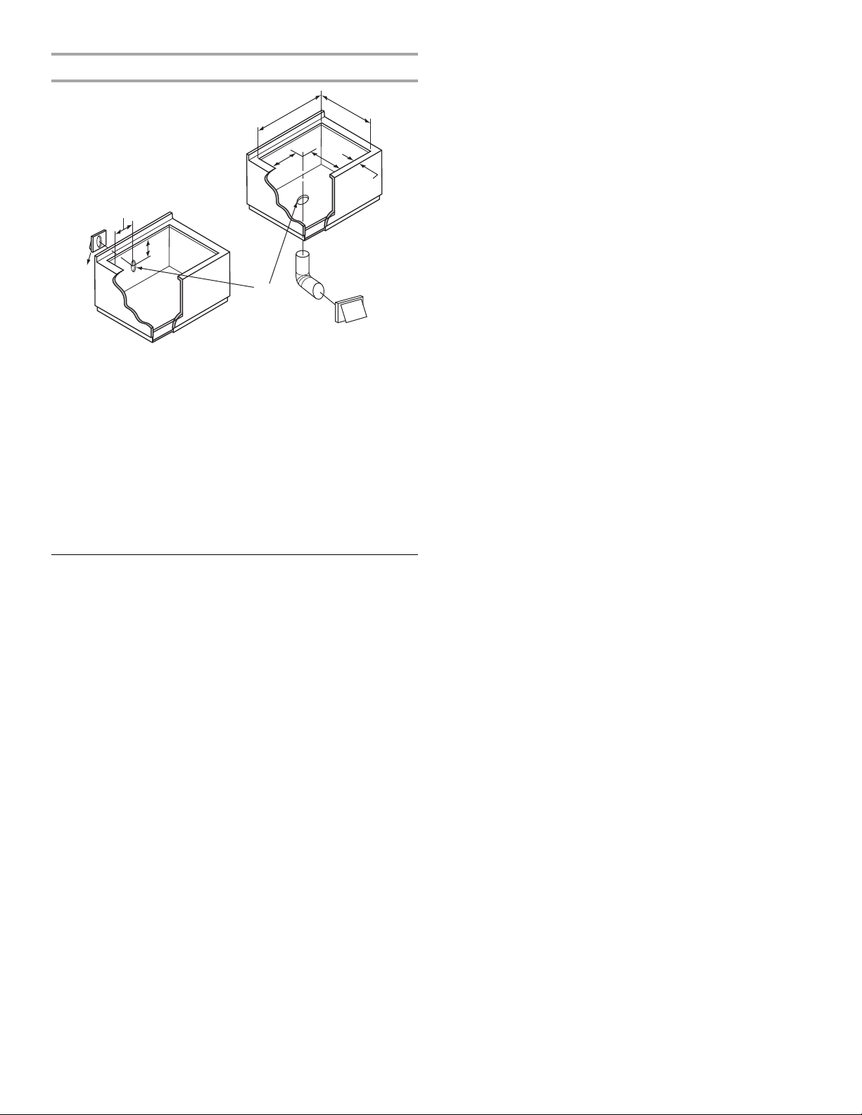
■ Provide cutout in right rear corner of cabinet enclosure as
shown to provide clearance for gas inlet, power supply cord,
and to allow the rating label to be visible.
■ If cabinet has drawers, drawers will need to be removed and
drawer fronts installed on front of cabinet.
IMPORTANT: An undercounter built-in oven cannot be installed
under this product.
IMPORTANT: To avoid damage to your cabinets, check with your
builder or cabinet supplier to make sure that the materials used
will not discolor, delaminate or sustain other damage. This
cooktop has been designed in accordance with the requirements
of UL and CSA International and complies with the maximum
allowable wood cabinet temperatures of 194°F (90°C).
Mobile Home - Additional Installation Requirements
The installation of this cooktop must conform to the
Manufactured Home Construction and Safety Standard, Title 24
CFR, Part 3280 (formerly the Federal Standard for Mobile Home
Construction and Safety, Title 24, HUD Part 280). When such
standard is not applicable, use the Standard for Manufactured
Home Installations, ANSI A225.1/NFPA 501A or local codes.
■ In Canada, the installation of this cooktop must conform with
the current standards CAN/CSA-A240-latest edition, or with
local codes.
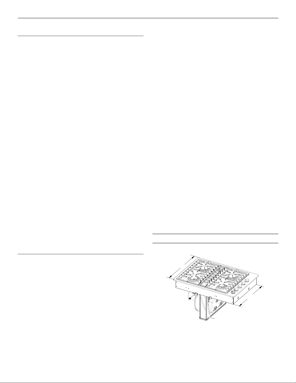
Product Dimensions
30" (76.2 cm) Cooktop
Location Requirements
IMPORTANT: Observe all governing codes and ordinances.
When installing cooktop, use minimum dimensions given.
■ It is the installer’s responsibility to comply with installation
clearances specified on the model/serial rating plate. The
model/serial rating plate is located on side of the downdraft
plenum.
■ To eliminate the risk of burns or fire by reaching over the
heated surface units, cabinet storage space located above
the surface units should be avoided. If cabinet storage is to
be provided, the risk can be reduced by installing a range
hood that projects horizontally a minimum of 5" (12.7 cm)
beyond the bottom of the cabinets.
■ The cooktop should be installed in a location away from
strong draft areas, such as windows, doors and strong
heating vents or fans.
A. 21½" (54.6 cm)
B. 19
¹¹⁄₁₆
" (50.0 cm)
C. Model/serial rating plate location
3
Page 4
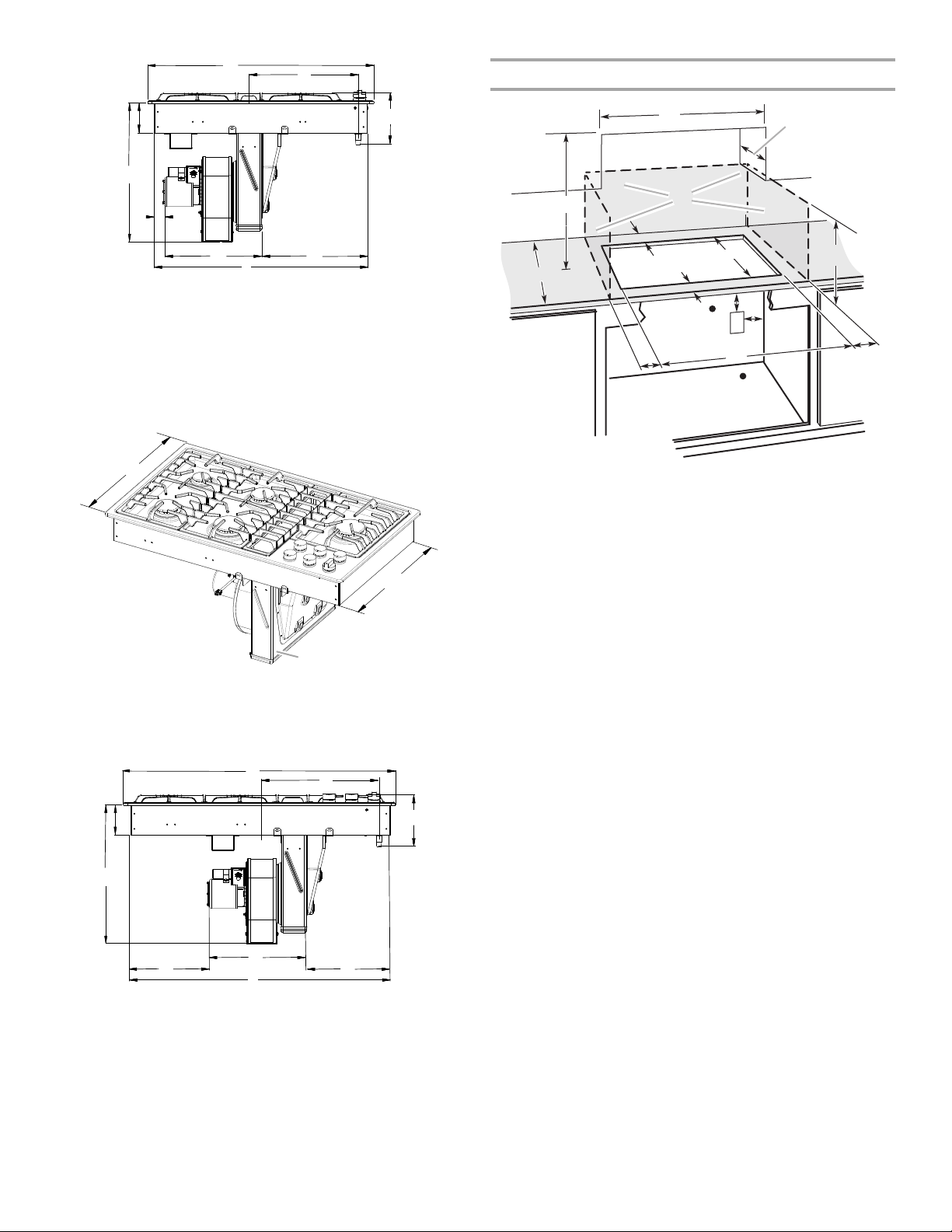
Cabinet Dimensions
A
B
C
D
E
F
G
H
I
C
A
B
A
B
D
C
E
F
I
G
H
B
D
A
E
F
H
I
K
L
K
M
M
C
G
N
J
A. 30" (76.2 cm)
B. 12
¹⁵⁄₁₆
" (32.9 cm) centerline of
cooktop to centerline of gas
manifold pipe
C. 4" (10.2 cm)
D. 6
¹⁹⁄₃₂
" (16.8 cm)
E. 18
⁷⁄₁₆
" (46.8 cm)
36" (91.4 cm) Cooktop
A. 21½" (54.6 cm)
B. 19
¹¹⁄₁₆
C. Model/serial rating plate location
" (50.0 cm)
¹¹⁄₁₆
" (4.3 cm) recommended
F. 1
minimum cabinet to motor
clearance
G. 12
¹⁄₂
" (31.8 cm)
H. 14" (35.6 cm)
I. 28¼" (71.4 cm)
A. 30" (76.2 cm) on 30" (76.2 cm) models
36" (91.4 cm) on 36" (91.4 cm) models
B. Combustible area above countertop (shown by dashed box above)
C. 30" (76.2 cm) minimum clearance between top of cooktop platform
and bottom of uncovered wood or metal cabinet (24" [61.0 cm]
minimum clearance if bottom of wood or metal cabinet is covered
by not less than ¼" [0.6 cm] flame retardant millboard covered with
not less than No. 28 MSG sheet steel, 0.015" [0.04 cm] stainless
steel, or 0.024" [0.06 cm] aluminum or 0.020" [0.05 cm] copper)
D. 13" (33.0 cm) recommended upper cabinet depth
E. 2
¹⁄₈
" (5.4 cm)
F. 1 9
¹⁵⁄₁₆
G. 18" (45.7 cm) minimum clearance from upper cabinet to countertop
H. Junction box or outlet; 12" (30.5 cm) minimum from bottom of
M. Gas line opening - Wall: anywhere 6" (15.2 cm) below underside of
N. 25" (63.5 cm) depth of countertop
" (50.6 cm)
within minimum horizontal clearances to cooktop
countertop
I. Junction box or outlet; 10" (25.4 cm) from right-hand side of
cabinet
J. 28
⁵⁄₈
" (72.7 cm) on 30" (76.2 cm) models
34¾" (88.3 cm) on 36" (91.4 cm) models
K. 6" (15.2 cm) minimum distance to nearest left and right side
combustible surface above cooktop
L. 2" (5.1 cm) minimum clearance between back wall and countertop
countertop. Cabinet floor: anywhere within 6" (15.2 cm) of rear wall
is recommended.
NOTES: After making the countertop cutout, some installations
may require notching down the base cabinet side walls to clear
the cooktop base. To avoid this modification, use a base cabinet
with sidewalls wider than the cutout.
■ A minimum side clearance of 6" (15.2 cm) is recommended
between side of cooktop and side wall for maximum
A. 36" (91.4 cm)
B. 15¾" (40.0 cm) centerline of
cooktop to centerline of gas
manifold pipe
C. 4" (10.2 cm)
D. 6
¹⁹⁄₃₂
" (16.8 cm)
E. 18
⁷⁄₁₆
" (46.8 cm)
³⁄₈
" (26.4 cm)
G. 12
H. 13" (33.0 cm)
F. 1 0
recommended minimum
cabinet to motor clearance
¹⁄₂
" (31.8 cm)
I. 34
³⁄₈
" (87.3 cm)
ventilation performance.
■ A minimum clearance of 2" (5.1 cm) is recommended
between the motor/blower and cabinet for proper cooling. A
6" (15.2 cm) clearance is recommended for servicing access.
4
Page 5
Cutout Dimensions
A
B
C
D
E
F
G
H
I
J
A. 28
⁵⁄₈
" (72.7 cm) maximum on 30" (76.2 cm) models
34¾" (88.3 cm) maximum on 36" (91.4 cm) models
B. 19
¹⁵⁄₁₆
" (50.6 cm) maximum on both 30" (76.2 cm) and 36" (91.4 cm)
models
C. 8½" (21.6 cm) on 30" (76.2 cm) models
17½" (44.4 cm) on 36" (91.4 cm) models
D. 5¾" (14.6 cm) on both 30" (76.2 cm) and 36" (91.4 cm) models
E. 2
¹⁄₈
" (5.4 cm) minimum space to front edge of cooktop
F. Floor exhaust option
G. 6
¹⁄₈
" (15.6 cm) for 6" vent system
H. 8½" (21.6 cm) on 30" (76.2 cm) models
17½" (44.4 cm) on 36" (91.4 cm) models
I. 16" (40.6 cm) on both 30" (76.2 cm) and 36" (91.4 cm) models
J. Wall exhaust option
Venting Requirements
IMPORTANT: This cooktop must be exhausted outdoors unless
using the Jenn-Air
Methods” section.
■ Do not terminate the vent system in an attic or other enclosed
area.
■ Use a Jenn-Air
■ Vent system must terminate to the outside.
■ Use only a 6" (15.2 cm) round metal vent. Rigid metal vent is
recommended. For best performance, do not use plastic or
metal foil vent.
■ Before making cutouts, make sure there is proper clearance
within the wall or floor for the exhaust vent.
■ Do not cut a joist or stud unless absolutely necessary. If a
joist or stud must be cut, then a supporting frame must be
constructed.
■ The size of the vent should be uniform.
■ The vent system must have a damper. If roof or wall cap has a
damper, do not use damper supplied with the range hood.
■ Use vent clamps to seal all joints in the vent system.
■ Use caulking to seal exterior wall or roof opening around the
cap.
■ Determine which venting method is best for your application.
®
Duct Free Filter Accessory Kit. See “Venting
®
vent cap.
For Best Performance:
■ Use 26-gauge minimum galvanized or 25-gauge minimum
aluminum metal vent. Poor quality pipe fittings can reduce
airflow. Flexible metal vent is not recommended.
NOTE: Local codes may require a heavier gauge material.
■ Metal duct may be reduced to 30-gauge galvanized steel or
26-gauge aluminized steel if allowed by local codes. This
reduction is based on information in the International
Residential Codes Section M1601.1 (2006 edition).
■ Do not install 2 elbows together.
■ Use no more than three 90° elbows.
■ If an elbow is used, install it as far away as possible from the
hood’s vent motor exhaust opening.
■ Make sure there is a minimum of 18" (45.7 cm) of straight
vent between the elbows if more than one elbow is used.
■ Elbows too close together can cause excess turbulence that
reduces airflow.
■ Do not use a 5" (12.7 cm) elbow in a 6" (15.2 cm) or 3¹⁄₄" x 10"
(8.3 x 25.4 cm) system.
■ Do not reduce to a 5" (12.7 cm) system after using
6" (15.2 cm) or 3¹⁄₄" x 10" (8.3 x 25.4 cm) fittings.
■ Avoid forming handmade crimps. Handmade crimps may
restrict airflow.
■ Use a Jenn-Air
®
vent cap for proper performance. If an
alternate wall or roof cap is used, be certain the cap size is
not reduced and that it has a backdraft damper.
■ Use vent clamps to seal all joints in the vent system.
■ Use caulking to seal exterior wall or roof opening around the
cap.
The length of vent system and number of elbows should be kept
to a minimum to provide efficient performance.
The maximum equivalent length of the vent system is 60 ft
(18.3 m). For altitudes above 4,500 ft (1272 m), reduce
recommended vent run by 20% for best performance.
Cold Weather Installations
An additional backdraft damper should be installed to minimize
backward cold air flow and a thermal break installed to minimize
conduction of outside temperatures as part of the vent system.
The damper should be on the cold air side of the thermal break.
Makeup Air
Local building codes may require the use of makeup air systems
when using ventilation systems greater than specified CFM of air
movement. The specified CFM varies from locale to locale.
Consult your HVAC professional for specific requirements in your
area.
5
Page 6

Venting Methods
A
B
A
B
A
B
A
B
A
B
C
D
E
F
G
H
I
J
L
M
K
N
Common venting methods are shown for a counter-mounted
downdraft cooktop. The cooktop may be vented through the wall
or floor.
Option 1 - Roof Venting Option 2 - Wall Venting
A. Roof cap
B. 6" (15.2 cm) round roof venting
Option 3 - Venting Between
Floor Joist
A. 6" (15.2 cm) round wall venting
B. Wall cap
Option 4 - Venting behind
Cabinet Kick Plate
Concrete Slab Installations - Exhaust Through Wall
A. Wall cap
B. 6" (15.2 cm) round metal vent
C. 16" (40.6 cm) maximum
D. 6" (15.2 cm) round PVC sewer pipe
E. 6" (15.2 cm) round metal vent
F. 6" (15.2 cm) round PVC coupling
G. Concrete slab
H. 6" (15.2 cm) round PVC sewer pipe
I. 6" (15.2 cm) round 90° PVC sewer pipe elbow
J. Tightly pack gravel or sand completely around pipe.
K. 30 ft (9.1 m) max.
L. 6" (15.2 cm) round 90° PVC sewer pipe elbow
M. 6" (15.2 cm) round PVC coupling
N. 12" (30.5 cm) minimum
A. Wall cap
B. 6" (15.2 cm) round wall venting
A. Wall cap
B. 6" (15.2 cm) round wall venting
®
Jenn-Air
Duct Free Filter Accessory Kit
(For model numbers JED3430, JED3536, JED4430, JED4536,
JGD3430 and JGD3536)
®
On select downdraft models, the Jenn-Air
Duct Free Filter
Accessory Kit Part Number JDA7000WX is now available. The
Jenn-Air® Duct Free Filter Accessory Kit is ideal for both new
construction and kitchen renovation projects because it provides
an easy alternative to the installation of metal ducting and venting
in the downdraft system outside the home. The kit includes all
required hardware, one filter and complete installation
instructions. For more information on the Jenn-Air
®
Duct Free
Filter Accessory Kit, contact your Jenn-Air dealer or call
1-800-JENNAIR (1-800-536-6247).
6
Page 7

Calculating Vent System Length
90˚ elbow
2 ft
(0.6 m)
6 ft (1.8 m)
wall cap
To calculate the length of the system you need, add the
equivalent feet (meters) for each vent piece used in the system.
Vent Piece 6" (15.2 cm) Round
45° elbow 2.5 ft
(0.8 m)
Example vent system
90° elbow 5.0 ft
(1.5 m)
6" (15.2 cm)
wall cap
3¹⁄₄" x 10" (8.3 cm x 25.4 cm)
to 6" (15.2 cm) transition
6" (15.2 cm) to 3¹⁄₄" x 10"
(8.3 cm x 25.4 cm) transition
3¹⁄₄" x 10" (8.3 cm x 25.4 cm)
to 6" (15.2 cm) 90° elbow
0.0 ft
(0.0 m)
4.5 ft
(1.4 m)
1 ft
(0.3 m)
5.0 ft
(1.5 m)
transition
6" (15.2 cm) to 3¹⁄₄" x 10"
(8.3 cm x 25.4 cm) 90° elbow
5.0 ft
(1.5 m)
transition
3¹⁄₄" x 10" (8.3 cm x 25.4 cm)
90° elbow
3¹⁄₄" x 10" (8.3 cm x 25.4 cm)
flat elbow
3¹⁄₄" x 10" (8.3 cm x 25.4 cm)
wall cap
5.0 ft
(1.5 m)
12.0 ft
(3.7 m)
0.0 ft
(0.0 m)
1- 90° elbow = 5 ft (1.5 m)
8 ft (2.4 m) straight = 8 ft (2.4 m)
1 - wall cap = 0 ft (0 m)
System length = 13 ft (3.9 m)
NOTE: Flexible vent is not recommended. Flexible vent creates
back pressure and air turbulence that greatly reduce
performance.
Electrical Requirements
IMPORTANT: The cooktop must be electrically grounded in
accordance with local codes and ordinances, or in the absence
of local codes, with the National Electrical Code, ANSI/NFPA 70
or Canadian Electrical Code, CSA C22.1.
This cooktop is equipped with an electronic ignition system that
will not operate if plugged into an outlet that is not properly
polarized.
If codes permit and a separate ground wire is used, it is
recommended that a qualified electrical installer determine that
the ground path is adequate.
A copy of the above code standards can be obtained from:
National Fire Protection Association
1 Batterymarch Park
Quincy, MA 02169-7471
CSA International
8501 East Pleasant Valley Road
Cleveland, Ohio 44131-5575
■ A 120 volt, 60 Hz, AC only, 15-amp, fused electrical circuit is
required. A time-delay fuse or circuit breaker is also
recommended. It is recommended that a separate circuit
serving only this cooktop be provided.
■ Electronic ignition systems operate within wide voltage limits,
but proper grounding and polarity are necessary. Check that
the outlet provides 120-volt power and is correctly grounded.
■ The wiring diagrams are provided with this cooktop. See
“Wiring Diagrams” on a separate sheet. The wiring diagrams
are located on the left underside of the cooktop base.
7
Page 8

Gas Supply Requirements
WARNING
Explosion Hazard
Use a new CSA International approved gas supply line.
Install a shut-off valve.
Securely tighten all gas connections.
If connected to LP, have a qualified person make sure
gas pressure does not exceed 14" (36 cm) water
column.
Examples of a qualified person include:
licensed heating personnel,
authorized gas company personnel, and
authorized service personnel.
Failure to do so can result in death, explosion, or fire.
†®TEFLON is a registered trademark of E.I. Du Pont De Nemours and Company.
A
B
C
Flexible metal appliance connector:
■ If local codes permit, use a ¹⁄₂" or ³⁄₄" I.D. flexible stainless
steel tubing gas connector, designed by CSA to connect
the cooktop to the rigid gas supply line.
■ A ½" male pipe thread is needed for connection to the
female pipe threads of the inlet to the cooktop pressure
regulator.
■ Do not kink or damage the flexible metal tubing when
moving the cooktop.
Rigid pipe connection:
The rigid pipe connection requires a combination of pipe
fittings to obtain an in-line connection to the cooktop. The
rigid pipe must be level with the cooktop connection. All
strains must be removed from the supply and fuel lines so
cooktop will be level and in line.
Observe all governing codes and ordinances.
IMPORTANT: This installation must conform with all local codes
and ordinances. In the absence of local codes, installation must
conform with American National Standard, National Fuel Gas
Code ANSI Z223.1 - latest edition or CAN/CGA B149 - latest
edition.
IMPORTANT: Leak testing of the cooktop must be conducted
according to the manufacturer’s instructions.
Type of Gas
Natural Gas:
This cooktop is design-certified by CSA International for use with
Natural gas or, after proper conversion, for use with LP gas.
■ This cooktop is factory set for use with Natural gas. If
converting to LP gas, see the “LP Gas Conversion”
instructions provided in the package containing literature.
The model/serial rating plate located on the underside of the
cooktop base has information on the types of gas that can be
used. If the types of gas listed do not include the type of gas
available, check with the local gas supplier.
LP Gas Conversion:
Conversion must be done by a qualified service technician.
No attempt shall be made to convert the cooktop from the gas
specified on the model/serial rating plate for use with a different
gas without consulting the serving gas supplier. See the Gas
Conversion instructions provided in the package containing
literature.
Gas Supply Line
■ Provide a gas supply line of ³⁄₄" (1.9 cm) rigid pipe to the
cooktop location. A smaller size pipe on longer runs may
result in insufficient gas supply. Pipe-joint compounds that
resist the action of LP gas must be used. Do not use
TEFLON®† tape. With LP gas, piping or tubing size should be
½" minimum. Usually, LP gas suppliers determine the size
and materials used in the system.
8
■ Must include a shutoff valve:
The supply line must be equipped with a manual shutoff
valve. This valve should be located in the same room but
external to the cooktop opening, such as an adjacent
cabinet. It must be accessible without removing the cooktop,
and it should be in a location that allows ease of opening and
closing. Do not block access to shutoff valve. The valve is for
turning on or shutting off gas to the cooktop.
A. Gas supply line
B. Shutoff valve “open” position
C. To cooktop
Gas Pressure Regulator
The gas pressure regulator supplied with this cooktop must be
used. The inlet pressure to the regulator should be as follows for
proper operation:
Natural Gas:
Minimum pressure: 5" (12.7 cm) WCP
Maximum pressure: 7" to 14" (17.8 cm to 35.5 cm) WCP
LP Gas:
Minimum pressure: 10" (25.4 cm) WCP
Maximum pressure: 14" (35.5 cm) WCP
Contact local gas supplier if you are not sure about the inlet
pressure.
Page 9

Burner Input Requirements
WARNING
Excessive Weight Hazard
Use two or more people to move and install cooktop.
Failure to do so can result in back or other injury.
A
D
E
C
A
E
F
B
A
B
C
D
E
Gas Supply Pressure Testing
Input ratings shown on the model/serial rating plate are for
elevations up to 2,000 ft (609.6 m).
For elevations above 2,000 ft (609.6 m), ratings should be
reduced at a rate of 4% for each 1,000 ft (304.8 m) above sea
level (not applicable for Canada).
INSTALLATION INSTRUCTIONS
Install Cooktop
Decide on the final location for the cooktop.
Gas supply pressure for testing regulator must be at least
1" water column pressure above the manifold pressure shown on
the model/serial rating plate.
Line pressure testing above ½ psi gauge (14" WCP)
The cooktop and its individual shutoff valve must be disconnected
from the gas supply piping system during any pressure testing of
that system at test pressures in excess of ½ psi (3.5 kPa).
Line pressure testing at ½ psi gauge (14" WCP) or lower
The cooktop must be isolated from the gas supply piping system
by closing its individual manual shutoff valve during any pressure
testing of the gas supply piping system at test pressures equal to
or less than ½ psi (3.5 kPa).
Rotate Blower - Optional
IMPORTANT: The following additional steps must be performed
if the product is being installed in peninsula or island cabinetry.
The blower exhaust scroll is shipped from the factory set to
exhaust straight out the back of the cabinet through an exterior
wall.
1. Open carton as instructed on product packaging.
2. Remove shipping materials and tape from cooktop.
3. Remove the removable grease filter by lifting the filter out.
4. For island or peninsula installations, go to the “Rotate Blower
- Optional” section.
A. Removable grease filter
5. Using 2 or more people, remove the cooktop from the carton.
REMEMBER: An undercounter built-in oven cannot be
installed under this cooktop.
6. Place cooktop right side up into the cutout.
NOTE: Make sure that the front edge of the cooktop is
parallel to the front edge of the countertop. If repositioning is
needed, lift entire cooktop up from the cutout to avoid
scratching the countertop.
7. Connect blower exhaust scroll to ducting.
8. Use vent clamps to secure the ducting to the blower exhaust
scroll.
9. Reinstall grease filter.
10. Reinstall vent grille.
A. Blower exhaust scroll
B. Plenum
C. Blower motor
To rotate blower:
1. Locate the 4 plastic plugs in the plenum bypass.
2. Use the pliers to remove the plastic plugs.
IMPORTANT: Do not throw away the plastic plugs. The
plastic plugs must be reinstalled after the blower exhaust
scroll has been rotated.
A. Blower motor
B. Exhaust scroll
C. Plenum
D. Top label
E. 10-32 machine nuts (4)
F. Motor mounting plate
D. Blower bypass
E. Plastic plugs (4)
9
Page 10

3. Insert the ³⁄₈" socket and extension into the hole and use the
B
A
D
C
E
A
WARNING
Explosion Hazard
Use a new CSA International approved gas supply line.
Install a shut-off valve.
Securely tighten all gas connections.
If connected to LP, have a qualified person make sure
gas pressure does not exceed 14" (36 cm) water
column.
Examples of a qualified person include:
licensed heating personnel,
authorized gas company personnel, and
authorized service personnel.
Failure to do so can result in death, explosion, or fire.
ratchet handle to loosen the nut half of a rotation. Repeat this
process for each of the 4 nuts.
4. With the nuts loosened, the blower exhaust scroll can be
easily rotated downward.
4. Verify the “Top” label is positioned as shown.
5. Retighten each nut with the ³⁄₈" socket, extension and ratchet.
6. Reinstall the 4 plastic plugs.
To rotate blower motor:
NOTE: The “Top” label location on the blower motor is at the
9 o’clock position.
1. Using a ratchet with a ³⁄₈" socket and supporting the motor
with one hand, remove the 4 machine nuts that attach the
blower motor to the exhaust scroll.
2. Remove the blower motor and wheel assembly from the weld
studs.
A. Top label
5. Follow steps 5 - 10 in the “Install Cooktop” section.
Make Gas Connection
A. Top label
B. Blower motor
C. Motor mounting plate
3. When the motor mounting plate clears the threaded weld
studs, rotate the assembly clockwise 90° and reinstall the
four #10-32 machine nuts.
10
D. Weld stud location
E. Blower wheel
1. Apply pipe-joint compound made for use with Natural and LP
gas to the smaller thread ends of the flexible connector
adapters (see C and G in the following illustration).
2. Attach one adapter to the gas pressure regulator and the
other adapter to the gas shutoff valve. Tighten both adapters,
being certain not to move or turn the gas pressure regulator.
3. Use a ¹⁵⁄₁₆" combination wrench and channel lock pliers to
attach the flexible connector to the adapters. Check that
connector is not kinked.
Page 11

Typical flexible connection
A
B
D
E
C
F
G
H
I
A
B
C
D
A
B
Electrical Shock Hazard
Plug into a grounded 3 prong outlet.
Do not remove ground prong.
Do not use an adapter.
Do not use an extension cord.
Failure to follow these instructions can result in death,
fire, or electrical shock.
WARNING
A. Manifold entrance
B. Gas pressure regulator
C. Use pipe-joint compound.
D. Adapter (must have ½" male pipe thread)
E. Flexible connector
F. A d a pt e r
G. Use pipe-joint compound.
H. Manual gas shutoff valve
I. ½" or ¾" gas pipe
4. Install the pressure regulator with the arrow pointing up
toward the bottom of the cooktop base and in a position
where you can reach the regulator access cap.
Complete Connection
1. Open the manual shutoff valve in the gas supply line. The
valve is open when the handle is parallel to the gas pipe.
A. Closed valve
B. Open valve
2. Test all connections by brushing on an approved
noncorrosive leak-detection solution. If bubbles appear, a
leak is indicated. Correct any leak found.
3. Remove surface burner caps and grates from parts package.
Align notches in burner caps with pins in burner base. Burner
caps should be level when properly positioned. If burner caps
are not properly positioned, surface burners will not light.
Place burner grates over burners and caps.
A. Access cap
B. Rear of cooktop
C. Gas pressure regulator
D. Up arrow. Regulator must be installed with
arrow pointing up to cooktop bottom.
IMPORTANT: All connections must be wrench-tightened. Do
not make connections to the gas regulator too tight. Making
the connections too tight may crack the regulator and cause
a gas leak. Do not allow the regulator to turn on the pipe
when tightening fittings.
Use only pipe-joint compound made for use with Natural and LP
gas.
Do not use TEFLON
required depending on your installation.
®
tape. You will need to determine the fittings
4. Plug into a grounded 3 prong outlet.
11
Page 12

Electronic Ignition System
A
B
Initial lighting and gas flame adjustments
This cooktop is equipped for electronic auto-reignition by means
of a spark igniter located at the rear of each burner. The burners
are designed to light at any valve rotation that admits sufficient
gas flow to support a flame and to automatically relight following
a loss of flame due to a draft or other adverse condition. This
feature is provided only as a convenience.
Check Operation of Surface Burners
Push in and turn the surface burners control knobs to light.
The surface burner flame should light within 4 seconds. The first
time a surface burner is lit, it may take longer that 4 seconds to
light because of air in the gas line.
Check the flame on “HIGH” for a blue color. It should be clean
and soft in character. No yellow tip, blowing or lifting of flame
should occur. Occasional orange flashes are normal and reflect
different elements in the air or gas.
After verifying the proper burner operation, turn the control knobs
to “OFF.”
If burners do not light properly:
■ Turn surface burner control knob to the “OFF” position.
■ Check that the power supply cord is plugged in and the
circuit breaker has not tripped or the fuse blown.
■ Check that the gas shutoff valves are set to the “open”
position.
■ Check that burner caps are properly positioned on burner
bases.
Recheck operation of surface burners. If a burner does not light
at this point, contact your dealer or authorized service company
for assistance.
Adjust Flame Height
Smart Port Burner System
This cooktop is equipped with a Smart Port Burner System. The
Smart Port Burner System produces a small flame directly under
each grate finger and a larger flame between each grate finger.
The visual difference between the ports will be noticeable when
the burner is used or when adjustments are made to the flame
length.
Adjust the height of top burner flames. The cooktop “low” burner
flame should be a steady blue flame approximately ¼" (0.64 cm)
high.
To adjust standard burners:
The flame can be adjusted using the adjustment screw in the
center of the valve stem. The valve stem is located directly
underneath the control knob.
If the “low” flame needs to be adjusted:
1. Light 1 burner and turn to lowest setting.
2. Remove the control knob.
3. Hold the knob stem in the low position using a pair of pliers.
Use an ¹⁄₈" (3.0 mm) flat-blade screwdriver to turn the screw
located in the center of the control knob stem until the flame
is the proper size.
4. Replace the control knob.
5. Test the flame by turning the control from “LO” to “HI,”
checking the flame at each setting.
6. Repeat above steps for each burner.
Complete Installation
1. Check that all parts are now installed. If there is an extra part,
go back through the steps to see which step was skipped.
2. Check that you have all your tools.
3. Dispose of/recycle all packaging materials.
4. Use a mild solution of liquid household cleaner and warm
water to clean cooktop before use. Dry thoroughly with a soft
cloth. For more information, see the “Cooktop Care” section
of the Use and Care Guide.
5. Read “Cooktop Use” in the cooktop Use and Care Guide.
6. Reconnect power.
NOTE: If the cooktop does not work after turning on the power,
check that a circuit breaker has not tripped or a household fuse
has not blown. See “Troubleshooting” section in the Use and
Care Guide for further information.
7. Use the Flow Tester Card provided with your cooktop to
check the airflow (see card for step-by-step instructions).
If you need Assistance or Service:
Please reference the “Assistance or Service” section of the Use
and Care Guide or contact the dealer from whom you purchased
your cooktop.
A. Low flame
B. High flame
12
Page 13

SÉCURITÉ DE LA TABLE DE CUISSON
Risque possible de décès ou de blessure grave si vous ne
suivez pas immédiatement les instructions.
Risque possible de décès ou de blessure grave si vous
ne suivez pas les instructions.
Tous les messages de sécurité vous diront quel est le danger potentiel et vous disent comment réduire le risque de blessure et
ce qui peut se produire en cas de non-respect des instructions.
Votre sécurité et celle des autres est très importante.
Nous donnons de nombreux messages de sécurité importants dans ce manuel et sur votre appareil ménager. Assurez-vous de
toujours lire tous les messages de sécurité et de vous y conformer.
AVERTISSEMENT
DANGER
Voici le symbole d’alerte de sécurité.
Ce symbole d’alerte de sécurité vous signale les dangers potentiels de décès et de blessures graves à vous
et à d’autres.
Tous les messages de sécurité suivront le symbole d’alerte de sécurité et le mot “DANGER” ou
“AVERTISSEMENT”. Ces mots signifient :
AVERTISSEMENT : Si les renseignements dans ce manuel ne sont pas exactement
observés, un incendie ou une explosion peut survenir, causant des dommages au
produit, des blessures ou un décès.
– Ne pas entreposer ni utiliser de l’essence ou d’autres vapeurs ou liquides inflammables
à proximité de cet appareil ou de tout autre appareil électroménager.
– QUE FAIRE DANS LE CAS D’UNE ODEUR DE GAZ :
•
Ne pas tenter d’allumer un appareil.
•
Ne pas toucher à un commutateur électrique.
•
Ne pas utiliser le téléphone se trouvant sur les lieux.
•
Appeler immédiatement le fournisseur de gaz à partir du téléphone d'un voisin. Suivre
ses instructions.
•
À défaut de joindre votre fournisseur de gaz, appeler les pompiers.
– L’installation et l’entretien doivent être effectués par un installateur qualifié, une agence
de service ou le fournisseur de gaz.
AVERTISSEMENT : L’odorat ne permet pas toujours la détection d’une fuite de gaz.
Les distributeurs de gaz recommandent l’emploi d’un détecteur de gaz (homologation UL ou CSA).
Pour d’autre information, contacter le fournisseur de gaz local.
En cas de détection d’une fuite de gaz, exécuter les instructions “Que faire dans le cas d’une odeur de gaz”.
IMPORTANT : Ne pas installer un système de ventilation avec évacuation de l'air vers le bas, qui évacuerait l'air vers cet
appareil de cuisson à gaz. Ce type de système de ventilation peut causer des problèmes d'allumage et de combustion avec cet
appareil de cuisson à gaz et entraîner des blessures corporelles ou le fonctionnement non désiré de cet appareil.
13
Page 14

EXIGENCES D'INSTALLATION
Dans l’État du Massachusetts, les instructions d’installation suivantes sont applicables :
■ Les travaux d’installation et réparation doivent être exécutés par un plombier ou tuyauteur qualifié ou licencié, ou par le
personnel qualifié d’une entreprise licenciée par l’État du Massachusetts.
■ Si une vanne à boisseau sphérique est utilisée, elle doit comporter une manette “T”.
■ Si un conduit de raccordement flexible est utilisé, sa longueur ne doit pas dépasser 3 pi.
Outillage et pièces
Rassembler les outils et composants nécessaires avant
d'entreprendre l'installation. Lire et observer les instructions
fournies avec chacun des outils de la liste ci-dessous.
Outils nécessaires
■ Mètre-ruban
■ Tournevis à lame plate
■ Tournevis Phillips
■ Perceuse
■ Niveau
■ Rallonge pour clé à douille
de 6" (15,2 cm)
■ Marqueur ou crayon
Pièces fournies
■ Grille de ventilation
■ Pré-filtre
■ Trousse de conversion
pour l'alimentation au
propane
Pièces nécessaires
■ Conduits métalliques
■ Brides de serrage pour conduit d’évacuation
■ Bouche de décharge murale Jenn-Air
Clapet de bouche de décharge murale à surface arrondie de
6" (15,2 cm) de Jenn-Air
Commander la pièce numéro A406
Clapet de bouche de décharge murale à surface de
3¼" x 10" (8,3 x 25,4 cm) de Jenn-Air
Commander la pièce numéro A403
Pour commander, voir la section “Assistance ou service” du
Guide d’utilisation et d’entretien.
Vérifier les codes locaux et consulter le fournisseur de gaz.
Vérifier l'alimentation en gaz et l'alimentation électrique
existantes. Voir les sections “Spécifications électriques” et
“Spécifications de l'alimentation en gaz”.
Il est recommandé de faire réaliser tous les raccordements
électriques par un électricien qualifié agréé.
■ Pince
■ Foret de ¼"
■ Scie sauteuse
■ Clé à cliquet avec douille
de ³⁄₈"
■ Composé d’étanchéité des
raccords filetés – résistant
au gaz propane
■ Solution non corrosive de
détection des fuites
■ Chapeaux de brûleur
■ Grilles de brûleur
■ Détendeur
®
®
IMPORTANT : Observer les dispositions de tous les codes et
règlements en vigueur. Lors de l’installation de la table de
cuisson, utiliser les dimensions minimums indiquées.
■ C'est à l'installateur qu'incombe la responsabilité de
respecter les distances de séparation exigées, spécifiées sur
la plaque signalétique de l'appareil. La plaque signalétique se
trouve sur le côté de la chambre de distribution à aspiration
par le bas.
■ Afin de supprimer le risque de brûlures ou d'incendie en se
penchant au-dessus des unités de surface chauffées, le
rangement en armoire au-dessus des unités de surface doit
être évité. Si un rangement en armoire est envisagé, le risque
peut être réduit par l'installation d'une hotte de cuisine
opérant horizontalement sur un minimum de 5" (12,7 cm)
au-delà du bas des placards.
■ La table de cuisson doit être installée dans un emplacement à
l’écart des zones de forts courants d’air, telles que fenêtres,
portes et évents ou ventilateurs de chauffage.
■ Toutes les ouvertures dans le mur ou le plancher de
l'emplacement d'installation de la table de cuisson doivent
être scellées.
■ Respecter les dimensions indiquées pour les ouvertures à
découper dans les placards. Ces dimensions constituent les
valeurs minimales des dégagements de séparation.
■ Une source d'électricité avec liaison à la terre est nécessaire.
Voir la section “Spécifications électriques”. Une source de
gaz adéquate doit être disponible. Voir la section
“Spécifications de l'alimentation en gaz”.
■ De par sa conception, la table de cuisson est suspendue sur
le plan de travail, par les rebords des côtés ou de l'arrière.
■ Veiller à placer les sources de gaz et d'électricité selon les
indications de la section “Dimensions du placard” pour
qu'elles soient accessibles sans avoir à retirer la table de
cuisson.
■ Prévoir une ouverture dans l'angle supérieur droit de
l'enceinte – voir l'illustration – pour le passage de la
canalisation de gaz et du câble d'alimentation électrique et
pour que l'étiquette signalétique soit visible.
■ Si le placard comporte des tiroirs, ces tiroirs doivent être
retirés et l'avant des tiroirs installé sur l'avant du placard.
IMPORTANT : Il n'est pas possible d'installer un four encastré
sous plan de travail sous ce produit.
IMPORTANT : Afin d'éviter d’endommager les placards,
Exigences d'emplacement
consulter le constructeur de la maison ou le fabricant des
placards pour déterminer si les matériaux utilisés peuvent subir
un changement de couleur, une déstratification ou d'autres
14
dommages. Cette table de cuisson a été conçue conformément
aux exigences des normes UL et CSA International et respecte
les températures maximales permises de 194°F (90°C) pour les
placards en bois.
Page 15

Résidence mobile – Spécifications additionnelles à
C
A
B
A
B
C
D
E
F
G
H
I
C
A
B
A
B
D
C
E
F
I
G
H
respecter lors de l'installation
L'installation de cette table de cuisson doit être conforme aux
dispositions de la norme Manufactured Home Construction and
Safety Standard, Title 24 CFR, Part 3280 (anciennement Federal
Standard for Mobile Home Construction and Safety, Title 24,
HUD Part 280). Lorsque cette norme n'est pas applicable, utiliser
la norme Standard for Manufactured Home Installations, ANSI
A225.1/NFPA 501A ou respecter les dispositions des codes
locaux.
■ Au Canada, l'installation de cette table de cuisson doit
satisfaire aux stipulations de la version la plus récente de la
norme CAN/CSA-A240 ou des codes locaux en vigueur.
Dimensions du produit
Table de cuisson de 36" (91,4 cm)
Table de cuisson de 30" (76,2 cm)
A. 21½" (54,6 cm)
B. 19
¹¹⁄₁₆
" (50,0 cm)
C. Emplacement de la plaque signalétique
A. 21½" (54,6 cm)
B. 19
¹¹⁄₁₆
" (50,0 cm)
C. Emplacement de la plaque signalétique
A. 36" (91,4 cm)
B. 15¾" (40,0 cm) entre l'axe
central de la table de cuisson
et l'axe central de la tubulure
de distribution de gaz
C. 4" (10,2 cm)
D. 6
¹⁹⁄₃₂
" (16,8 cm)
⁷⁄₁₆
" (46,8 cm)
E. 18
F. Dégagement minimal
recommandé de 10
(26,4 cm) entre le placard et le
moteur
G. 12
¹⁄₂
" (31,8 cm)
H. 13" (33,0 cm)
I. 34
³⁄₈
" (87,3 cm)
³⁄₈
"
⁷⁄₁₆
" (46,8 cm)
A. 30" (76,2 cm)
¹⁵⁄₁₆
B. 12
C. 4" (10,2 cm)
D. 6
" (32,9 cm) entre l'axe
central de la table de cuisson
et l'axe central de la tubulure
de distribution de gaz
¹⁹⁄₃₂
" (16,8 cm)
E. 18
F. Dégagement minimal
recommandé de 1
entre le placard et le moteur
G. 12
¹⁄₂
H. 14" (35,6 cm)
I. 28¼" (71,4 cm)
" (31,8 cm)
¹¹⁄₁₆
" (4,3 cm)
15
Page 16

Dimensions du placard
B
D
A
E
F
H
I
K
L
K
M
M
C
G
N
J
A
B
C
D
E
F
G
H
I
J
A. 30" (76,2 cm) sur les modèles de 30" (76,2 cm)
36" (91,4 cm) sur les modèles de 36" (91,4 cm)
B. Zone de matière combustible au-dessus du plan de travail (espace
délimité par des lignes pointillées ci-dessus)
C. Distance minimale de séparation de 30" (76,2 cm) entre le dessus de
la table de cuisson et le fond d'un placard métallique ou de bois non
couvert (distance de séparation de 24" [61 cm] ou plus si le fond du
placard de métal ou de bois est recouvert d'une plaque d'au moins
¼" (0,6 cm) de matériau résistant aux flammes, lui-même recouvert
d'une feuille métallique d'une épaisseur correspondant à un calibre
de 28 au moins pour l'acier, 0,015" [0,04 cm] pour l'acier inoxydable,
0,024" [0,06 cm] pour l'aluminium ou 0,020" [0,05 cm] pour le cuivre)
D. Profondeur recommandée pour les placards supérieurs : 13" (33,0 cm)
E. 2
¹⁄₈
" (5,4 cm)
F. 1 9
¹⁵⁄₁₆
G. Distance de séparation minimale de 18" (45,7 cm) entre le placard
H. Boîtier de connexion ou prise électrique; 12" (30,5 cm) ou plus
M. Ouverture pour canalisation de gaz – mur : n'importe où, à 6"
N. Profondeur de la table de cuisson 25" (63,5 cm)
REMARQUES : Après le découpage de l'ouverture dans le plan
de travail, il est possible que pour certaines configurations
d'installation, il soit nécessaire d'entailler les parois latérales du
placard inférieur pour permettre le passage de la base de la table
de cuisson. Pour éviter cette modification, utiliser un placard
inférieur dont la largeur des parois latérales est supérieure à celle
de l'ouverture découpée.
■ Un dégagement minimum de 6" (15,2 cm) entre le côté de la
■ Un dégagement minimum de 2" (5,1 cm) entre le moteur/
" (50,6 cm)
supérieur et le plan de travail avec distance minimale de séparation
horizontale pour la table de cuisson
depuis le bas du plan de travail
I. Boîtier de connexion ou prise électrique; 10" (25,4 cm) depuis le
côté droit du placard
J. 28
⁵⁄₈
" (72,7 cm) sur les modèles de 30" (76,2 cm)
34¾" (88,3 cm) sur les modèles de 36" (91,4 cm)
K. Distance de séparation minimale de 6" (15,2 cm) par rapport à la
surface de matériau combustible la plus proche, à gauche ou à
droite au-dessus de la table de cuisson
L. Distance de séparation minimale de 2" (5,1 cm) ou plus entre la
paroi arrière et le plan de travail
(15,2 cm) au-dessous de la face inférieure du plan de travail.
Plancher du placard : n'importe où, à 6" (15,2 cm) maximum du
mur arrière (recommandation)
table de cuisson et la paroi latérale est recommandé pour une
performance maximale de ventilation.
ventilateur et le placard est recommandé pour que le
refroidissement puisse s'effectuer correctement. Un
dégagement de 6" (15,2 cm) est recommandé pour avoir
accés en cas de réparations.
Dimensions de l’ouverture à découper
A. 28
⁵⁄₈
" (72,7 cm) maximum sur les modèles de 30" (76,2 cm)
34¾" (88,3 cm) maximum sur les modèles de 36" (91,4 cm)
B. 19
¹⁵⁄₁₆
" (50,6 cm) maximum sur les modèles de 30" (76,2 cm) et de
36" (91,4 cm)
C. 8½" (21,6 cm) sur les modèles de 30" (76,2 cm)
17½" (44,4 cm) sur les modèles de 36" (91,4 cm)
D. 5¾" (14,6 cm) sur les modèles de 30" (76,2 cm) et de 36" (91,4 cm)
E. Dégagement minimal de 2
table de cuisson
F. Option d'évacuation par le plancher
G. 6
¹⁄₈
" (15,6 cm) pour un système d'évacuation de 6"
H. 8½" (21,6 cm) sur les modèles de 30" (76,2 cm)
17½" (44,4 cm) sur les modèles de 36" (91,4 cm)
I. 16" (40,6 cm) sur les modèles de 30" (76,2 cm) et de 36" (91,4 cm)
J. Option d'évacuation par le mur
¹⁄₈
" (5,4 cm) jusqu'au rebord avant de la
Exigences concernant l'évacuation
IIMPORTANT : L'évacuation de cette table de cuisson doit se
faire à l'extérieur à moins d'utiliser la trousse accessoire de
filtration sans conduit de Jenn-Air®. Voir la section “Méthodes
d'évacuation”.
■ Ne pas terminer le circuit d'évacuation dans un grenier ou
dans un autre espace fermé.
■ Utiliser un clapet de conduit Jenn-Air
■ Le système doit décharger l'air à l'extérieur.
■ Utiliser uniquement du conduit métallique de 6" (15,2 cm). Un
conduit en métal rigide est recommandé. Pour un rendement
optimal, ne pas utiliser de conduit en plastique ou en
aluminium.
■ Avant d'effectuer des découpes, s'assurer qu'il y a un
dégagement convenable entre le mur ou le plancher pour le
conduit d'évacuation.
■ On ne doit couper un poteau de colombage ou une solive
que si c’est absolument nécessaire. Dans ce cas, on devra
construire une structure de support appropriée.
■ La taille du conduit doit être uniforme.
■ Le circuit d'évacuation doit comporter un clapet. Si la bouche
de décharge murale ou par le toit comporte un clapet, ne pas
utiliser le clapet fourni avec la hotte de cuisinière.
■ Au niveau de chaque jointure du circuit d'évacuation, assurer
l'étanchéité avec les brides de serrage.
■ À l'aide d'un produit de calfeutrage, assurer l'étanchéité
autour de la bouche de décharge à l'extérieur (à travers le
mur ou le toit).
■
Déterminer quelle méthode d'évacuation est la plus appropriée.
®
.
16
Page 17

Pour obtenir la meilleure performance :
A
B
A
B
A
B
A
B
3¹⁄₄" x 10"
(8,3 x 25,4 cm)
■ Utiliser un conduit de ventilation en acier galvanisé
d'épaisseur minimum nº 26 ou en aluminium d'épaisseur
minimum nº 25. Des raccords de mauvaise qualité peuvent
réduire le flux d'air. On déconseille l’emploi d’un conduit en
métal flexible.
REMARQUE : Les codes locaux pourraient exiger un
matériau plus épais.
■ Le conduit métallique peut être réduit à une épaisseur
nº 30 pour l'acier galvanisé ou nº 26 pour l'acier aluminisé si
c'est permis par les codes locaux. Cette information est
basée sur le contenu de la Section des Codes Résidentiels
Internationaux M1601.1 (édition 2006).
■ Ne pas installer 2 coudes ensemble.
■ Ne pas utiliser plus de trois coudes à 90°.
■ Si l'on utilise un coude, on doit le placer le plus loin possible
de l’ouverture d'évacuation du moteur de la hotte de
ventilation.
■ Veiller à incorporer une section de conduit rectiligne d'au
moins 18" (45,7 cm) entre deux raccords coudés adjacents.
■ Des coudes trop rapprochés peuvent occasionner une
turbulence excessive qui réduirait la circulation de l'air.
■ Ne pas utiliser un coude de 5" (12,7 cm) dans un système de
6" (15,2 cm) ou 3¹⁄₄" x 10" (8,3 x 25,4 cm).
■ Ne pas réduire le système à une longueur de 5" (12,7 cm)
après avoir utilisé des raccords de 6" (15,2 cm) ou de 3¹⁄₄" x
10" (8,3 x 25,4 cm).
■ Éviter le sertissage manuel. Cela pourrait restreindre le flux
d'air.
■ Utiliser un clapet de conduit Jenn-Air
®
pour que le rendement
soit correct. Si une bouche de décharge murale ou de toit est
utilisée, s'assurer que la taille de la bouche de décharge n'est
pas réduite et qu'elle comporte un clapet anti-reflux.
■ Au niveau de chaque jointure du circuit d'évacuation, assurer
l'étanchéité avec les brides de serrage.
■ À l'aide d'un produit de calfeutrage, assurer l'étanchéité
autour de la bouche de décharge à l'extérieur (à travers le
mur ou le toit).
La longueur du système d'évacuation et le nombre de coudes
doit être réduit au minimum pour une performance efficace.
La longueur maximale équivalente du circuit d'évacuation est de
60 pi (18,3 m). Pour les altitudes excédant 4 500 pi (1 272 m),
réduire la longueur du système d'évacuation de 20 % pour une
performance optimale.
Installations pour régions à climat froid
On devrait installer un clapet anti-reflux additionnel pour
minimiser le reflux d’air froid, et incorporer un élément d’isolation
thermique pour minimiser la conduction de chaleur par
l’intermédiaire du conduit d’évacuation, de l’intérieur de la
maison à l’extérieur. Le clapet anti-reflux doit être placé du côté
air froid par rapport à l’élément d’isolation thermique.
Air d’appoint
Le code du bâtiment local peut exiger l’emploi d’un système de
renouvellement de l’air/introduction d’air d’appoint, lors de
l’utilisation d’un système d’aspiration de débit supérieur à une
valeur (pieds cubes par minute) spécifiée. Le débit spécifié en
pieds cubes par minute varie d’une juridiction à l'autre. Consulter
un professionnel des installations de chauffage/ventilation/
climatisation au sujet des exigences spécifiques applicables
dans la juridiction locale.
Méthodes d'évacuation
Les méthodes d'évacuation standard illustrées correspondent à
une table de cuisson avec aspiration par le bas montée sur
comptoir. L'évacuation de la table de cuisson peut se faire par le
mur ou le plancher.
Option 1 - Décharge à
travers le toit
A. Bouche de décharge sur toit
B. Conduit de dia. 6" (15,2 cm)
pour sortie à travers le toit
Option 3 - Évacuation entre
les solives au plancher
Option 2 - Décharge à
travers le mur
A. Conduit de dia. 6" (15,2 cm)
pour sortie à travers le mur
B. Bouche de décharge murale
Option 4 - Évacuation
derrière le garde-pieds de
la caisse
A. Bouche de décharge murale
B. Conduit de dia. 6" (15,2 cm)
pour sortie à travers le mur
A. Bouche de décharge murale
B. Conduit de dia. 6" (15,2 cm)
pour sortie à travers le mur
17
Page 18

Installations dans dalle de béton - Évacuation à travers le mur
A
B
C
D
E
F
G
H
I
J
L
M
K
N
coude à 90˚
2 pi
(0,6 m)
6 pi (1,8 m)
bouche de décharge murale
Raccord de transition de
3¹⁄₄" x 10" (8,3 cm x 25,4 cm)
sur 6" (15,2 cm)
4,5 pi (1,4 m)
A. Bouche de décharge murale
B. Conduit métallique de dia. 6" (15,2 cm)
C. 16" (40,6 cm) maximum
D. Conduit PVC pour égout de dia. 6" (15,2 cm)
E. Conduit métallique de dia. 6" (15,2 cm)
F. Raccord PVC de dia. 6" (15,2 cm)
G. Dalle de béton
H. Conduit PVC pour égout de dia. 6" (15,2 cm)
I. Coude à 90° en PVC pour égout de dia. 6" (15,2 cm)
J. Gravier ou sable compacté tout autour du tuyau.
K. 30 pi (9,1 m) max.
L. Coude à 90° en PVC pour égout de dia. 6" (15,2 cm)
M. Raccord PVC de dia. 6" (15,2 cm)
N. 12" (30,5 cm) minimum
Trousse accessoire de filtration sans conduit Jenn-Air
®
(Pour les modèles numéros JED3430, JED3536, JED4430,
JED4536, JGD3430 et JGD3536)
Sur certains modèles à extraction par le bas, la trousse
accessoire de filtration sans conduit Jenn-Air
®
, pièce
nº JDA7000WX est désormais disponible. La trousse accessoire
de filtration sans conduit Jenn-Air® est idéale tant pour les
nouvelles constructions que les projets de rénovation de cuisine
parce qu'elle offre une alternative facile à l'installation de
conduits métalliques et à la décharge de système à aspiration par
le bas vers l'extérieur du domicile. Cet ensemble comprend tout
le matériel nécessaire, un filtre et des instructions d'installation
complètes. Pour plus d'information concernant la trousse
accessoire de filtration sans conduit Jenn-Air
®
, contacter votre
concessionnaire Jenn-Air ou composer le 1-800-JENNAIR
(1-800-536-6247).
Raccord de transition de 6"
1 pi (0,3 m)
(15,2 cm) à 3¹⁄₄" x 10"
(8,3 cm x 25,4 cm)
Coude de transition à 90° de
5 pi (1,5 m)
3¹⁄₄" x 10" (8,3 cm x 25,4 cm)
à 6" (15,2 cm)
Coude de transition à 90° de 6"
5 pi (1,5 m)
(15,2 cm) à 3¹⁄₄" x 10" (8,3 cm x
25,4 cm)
Coude à 90° de
3¹⁄₄" x 10" (8,3 cm x 25,4 cm) 5 pi (1,5 m)
Coude plat de
3¹⁄₄" x 10" (8,3 cm x 25,4 cm) 12 pi (3,7 m)
Bouche de décharge murale
3¹⁄₄" x 10" (8,3 cm x 25,4 cm) 0 pi (0,0 m)
Exemple de circuit d'évacuation
Calcul de la longueur effective du circuit d'évacuation
Pour calculer la longueur effective du circuit d’évacuation
nécessaire, additionner les longueurs équivalentes (pieds/mètres)
de tous les composants utilisés dans le système.
Composant Conduit de diamètre de 6"
Coude à 45° 2,5 pi (0,8 m)
Coude à 90° 5 pi (1,5 m)
Bouche de décharge murale de
6" (15,2 cm)
18
(15,2 cm)
0 pi (0 m)
1 - coude à 90° = 5 pi (1,5 m)
Section droite de 8 pi (2,4 m) = 8 pi (2,4 m)
1 - bouche de décharge murale = 0 pi (0,0 m)
Longueur totale = 13 pi (3,9 m)
REMARQUE : On déconseille l’emploi d’un conduit flexible. Un
conduit flexible peut causer une rétro-pression et des
turbulences de l’air, ce qui réduit considérablement la
performance.
Page 19

Spécifications électriques
AVERTISSEMENT
Risque d'explosion
Utiliser une canalisation neuve d'arrivée de gaz
approuvée par la CSA International.
Installer un robinet d'arrêt.
Bien serrer chaque organe de connexion de la
canalisation de gaz.
En cas de connexion au gaz propane, demander à une
personne qualifiée de s'assurer que la pression de gaz
ne dépasse pas 36 cm (14 po) de la colonne d'eau.
Par personne qualifiée, on comprend :
le personnel autorisé de chauffage,
le personnel autorisé d'une compagnie de gaz, et
le personnel d'entretien autorisé.
Le non-respect de ces instructions peut causer
un décès, une explosion ou un incendie.
IMPORTANT : La table de cuisson doit être correctement reliée à
la terre en conformité avec les codes et règlements locaux en
vigueur, ou en l'absence de tels codes, avec le National Electrical
Code, ANSI/NFPA 70 ou le Code canadien des installations
électriques, CSA C22.1.
Cette table de cuisson est dotée d'un système d'allumage
électronique qui ne fonctionnera pas en cas de branchement
dans une prise qui n'est pas correctement polarisée.
Si les codes le permettent et si on utilise un conducteur distinct
de liaison à la terre, il est recommandé qu'un électricien qualifié
vérifie la qualité de la liaison à la terre.
Pour obtenir un exemplaire de la norme des codes ci-dessus,
contacter :
National Fire Protection Association
1 Batterymarch Park
Quincy, MA 02169-7471
CSA International
8501 East Pleasant Valley Road
Cleveland, OH 44131-5575
■ L'appareil doit être alimenté par un circuit de 120 V, CA
seulement, 60 Hz, 15 ampères, protégé par fusible. On
recommande également d'utiliser un fusible ou un disjoncteur
temporisé. Il est recommandé de raccorder la table de
cuisson sur un circuit distinct exclusif à cet appareil.
■ Les systèmes d'allumage électronique fonctionnent avec des
limites de tension étendues, mais une liaison à la terre
correcte et une polarité appropriée sont nécessaires. Vérifier
que la prise fournit une alimentation de 120 V et qu'elle est
correctement reliée à la terre.
■ Les schémas de câblage sont fournis avec cette table de
cuisson. Voir la section “Schémas de câblage” sur une feuille
séparée. Les schémas de câblage se trouvent sur la partie
inférieure de la base de la table de cuisson, du côté gauche.
Spécifications de l'alimentation en gaz
Observer les dispositions de tous les codes et règlements en
vigueur.
IMPORTANT : L'installation doit satisfaire aux critères de tous les
codes et règlements locaux. En l'absence de code local,
l'installation doit satisfaire aux prescriptions de la plus récente
édition du code national américain en vigueur : National Fuel Gas
Code ANSI Z223.1 ou à la norme CAN/CGA B149.
IMPORTANT : Les tests de fuite de la table de cuisson doivent
être effectués selon les instructions du fabricant.
Type de gaz
Gaz naturel :
La conception de cette table de cuisson a été homologuée par
CSA International pour l'alimentation au gaz naturel, ou pour
l'alimentation au propane après conversion adéquate.
■ Cette table de cuisson a été configurée à l'usine pour
l'alimentation au gaz naturel. Pour la conversion pour
l'alimentation au propane, voir les instructions “Conversion
pour l'alimentation au propane” dans le sachet de
documentation. La plaque signalétique située sur la face
inférieure de la base de la table de cuisson indique les types
de gaz utilisables. Si le type de gaz disponible n'est pas
mentionné sur la plaque signalétique, consulter le fournisseur
de gaz local.
Conversion pour l'alimentation au propane :
L'opération de conversion doit être exécutée par un technicien
de réparation qualifié.
Ne pas entreprendre de convertir la table de cuisson pour
l'utilisation d'un gaz différent de celui indiqué sur la plaque
signalétique sans d'abord consulter le fournisseur de gaz. Voir les
instructions de conversion de gaz fournies dans le sachet de
documentation.
19
Page 20

Canalisation de gaz
†®TEFLON est une marque déposée de E.I. Du Pont De Nemours et Compagnie
A
B
C
Détendeur de gaz
■ Installer une canalisation de gaz rigide de ¾" (1,9 cm) jusqu'à
l'emplacement d'installation de la table de cuisson. L'emploi
d'une canalisation de plus petit diamètre sur un circuit plus
long peut causer une déficience du débit d'alimentation. On
doit utiliser un composé d'étanchéité des tuyauteries
résistant à l'action du gaz propane. Ne pas utiliser de ruban
TEFLON
®†
. Pour l'alimentation au propane, le diamètre du
tuyau ou conduit doit être de ½" ou plus. Usuellement, le
fournisseur de gaz propane détermine les matériaux à utiliser
et le diamètre approprié.
Raccord métallique flexible :
■ Si les codes locaux le permettent, utiliser un connecteur à
gaz flexible en acier inoxydable de ½" ou ¾" de diamètre
interne, conçu par CSA pour raccorder la table de
cuisson à la canalisation rigide d'alimentation en gaz.
■ Un raccord avec filetage mâle de ½" est nécessaire pour
la connexion sur le raccord à filetage femelle à l'entrée du
détendeur de la table de cuisson.
■ Ne pas déformer, écraser ou endommager le tube
métallique flexible lors d'un déplacement de la table de
cuisson.
Raccordement par un ensemble rigide :
On doit utiliser une combinaison de raccords pour réaliser un
raccordement rigide entre la table de cuisson et la
canalisation de gaz. Le tuyau rigide doit se trouver au même
niveau que le raccord de connexion de la table de cuisson.
On doit veiller à ne soumettre les sections de canalisation
d'alimentation et de combustible à aucun effort de traction ou
flexion pour que la table de cuisson soit d'aplomb et
correctement alignée.
■ Robinet d'arrêt nécessaire :
La canalisation d'alimentation doit comporter un robinet
d'arrêt manuel. Le robinet d'arrêt manuel doit être séparé de
l'ouverture d'encastrement de la table de cuisson, mais doit
se trouver dans la même pièce, comme par exemple un
placard adjacent. II doit se trouver en un endroit facilement
accessible et qui ne nécessite pas le démontage de la table
de cuisson pour les manœuvres d'ouverture/fermeture. Ne
pas entraver l'accès au robinet d'arrêt manuel. Le robinet
d'arrêt manuel est prévu pour ouvrir ou fermer l'alimentation
en gaz de la table de cuisson.
Le détendeur fourni avec cette table de cuisson doit être utilisé.
La pression d'alimentation du détendeur doit être comme suit
pour un fonctionnement correct :
Gaz naturel :
Pression minimum : 5" (12,7 cm) (colonne d'eau)
Pression maximum : 7" à 14" (17,8 cm à 35,5 cm) (colonne d'eau)
Gaz propane :
Pression minimum : 10" (25,4 cm) (colonne d'eau)
Pression maximum : 14" (35,5 cm) (colonne d'eau)
En cas d'incertitude quant à la pression d'alimentation à établir,
contacter le fournisseur de gaz local.
Caractéristiques d'alimentation du brûleur
Les débits thermiques indiqués sur la plaque signalétique
correspondent à une altitude d'utilisation inférieure ou égale à
2000 pi (609,6 m).
Lorsque l'appareil est utilisé à une altitude supérieure à
2000 pi (609,6 m), on doit réduire le débit thermique indiqué
de 4 % pour chaque tranche de 1000 pi (304,8 m) au-dessus
du niveau de la mer (non applicable au Canada).
Test de pressurisation de la canalisation de gaz
On doit tester le détendeur sous une pression supérieure d'au
moins 1" (colonne d’eau) à la pression de la tubulure de
distribution indiquée sur la plaque signalétique.
Pressurisation à une pression supérieure à ½ lb/po²
(14" - colonne d'eau)
Lors de tout test de pressurisation de ce système à une pression
supérieure à ½ lb/po² (3,5 kPa), on doit déconnecter la table de
cuisson et son robinet d'arrêt individuel de la canalisation de gaz.
Pressurisation à une pression inférieure ou égale à ½ lb/po²
(14" - colonne d'eau)
Lors de tout test de pressurisation de la canalisation de gaz à une
pression égale ou inférieure à ½ lb/po² (3,5 kPa), on doit isoler la
table de cuisson de la canalisation de gaz en fermant son robinet
d'arrêt manuel individuel.
A. Canalisation de gaz
B. Robinet d'arrêt - position d'ouverture
C. Vers la table de cuisson
20
Page 21

INSTRUCTIONS D’INSTALLATION
AVERTISSEMENT
Risque du poids excessif
Utiliser deux ou plus de personnes pour déplacer et
installer la table de cuisson.
Le non-respect de cette instruction peut causer
une blessure au dos ou d'autre blessure.
A
D
E
C
A
E
F
B
A
B
C
D
E
Installation de la table de cuisson
Déterminer l’emplacement final de la table de cuisson.
1. Ouvrir le carton tel que stipulé sur l'emballage du produit.
2. Enlever les matériaux d’expédition et le ruban adhésif de la
table de cuisson.
3. Retirer le filtre à graisse amovible en le soulevant.
4. Pour des installations en îlot ou en péninsule, passer à la
section “Rotation du ventilateur - Facultative”.
Rotation du ventilateur - Facultative.
IMPORTANT : Les étapes supplémentaires suivantes doivent
être exécutées si le produit est installé avec une configuration
d'ébénisterie en péninsule ou en îlot.
La volute d'évacuation est montée à l'usine de manière à ce que
le système d'évacuation soit orienté directement vers l'arrière du
placard à travers un mur extérieur.
A. Volute d'évacuation du
ventilateur
B. Chambre de distribution
C. Moteur du ventilateur
D. Étiquette sur surface
supérieure
E. (4) écrous à métaux de 10-32
F. Platine de montage du moteur
A. Filtre à graisse amovible
5. À l'aide d'au moins 2 personnes, retirer la table de cuisson du
carton.
NE PAS OUBLIER : Il n'est pas possible d'installer un four
encastré sous plan de travail sous cette table de cuisson.
6. Placer la table de cuisson dans l'ouverture, face supérieure
vers le haut.
REMARQUE : S’assurer que le bord avant de la table de
cuisson est parallèle au bord avant du plan de travail. S'il est
nécessaire de repositionner la table de cuisson, la soulever
entièrement de l'ouverture pour éviter de rayer le plan de
travail.
7. Connecter la volute d'évacuation du ventilateur aux conduits.
8. Utiliser des brides de conduit pour fixer les conduits à la
volute d'évacuation du ventilateur.
9. Réinstaller le filtre à graisse.
10. Réinstaller la grille de ventilation.
Pour faire pivoter le ventilateur :
1. Repérer les 4 bouchons en plastique dans le système de
dérivation de la chambre de distribution.
2. Retirer les bouchons d'obturation en plastique à l'aide d'une
pince.
IMPORTANT : Ne pas jeter les bouchons d'obturation en
plastique. Les bouchons d'obturation en plastique doivent
être réinstallés après que l'on ait fait pivoté la volute
d'évacuation du ventilateur.
A. Moteur du ventilateur
B. Volute d'évacuation
C. Chambre de
distribution
3. Insérer la douille de ³⁄₈" et la rallonge dans le trou et utiliser le
manche de la clé à cliquet pour desserrer l'écrou d'un demitour. Répéter cette opération pour chacun des 4 écrous.
D. Système de dérivation
du ventilateur
E. Bouchons d'obturation
en plastique (4)
21
Page 22

4. Il est facile de faire pivoter la volute d'évacuation du
B
A
D
C
E
A
AVERTISSEMENT
Risque d'explosion
Utiliser une canalisation neuve d'arrivée de gaz
approuvée par la CSA International.
Installer un robinet d'arrêt.
Bien serrer chaque organe de connexion de la
canalisation de gaz.
En cas de connexion au gaz propane, demander à une
personne qualifiée de s'assurer que la pression de gaz
ne dépasse pas 36 cm (14 po) de la colonne d'eau.
Par personne qualifiée, on comprend :
le personnel autorisé de chauffage,
le personnel autorisé d'une compagnie de gaz, et
le personnel d'entretien autorisé.
Le non-respect de ces instructions peut causer
un décès, une explosion ou un incendie.
ventilateur vers le bas une fois les écrous desserrés.
5. Resserrer chaque écrou à l'aide de la douille de ³⁄₈", de la
rallonge et de la clé à cliquet.
6. Réinstaller les 4 bouchons d'obturation en plastique.
4. Vérifier que l'étiquette “surface supérieure” est positionnée
tel qu'illustré.
Pour faire pivoter le moteur du ventilateur :
REMARQUE : L'étiquette “surface supérieure” du moteur de
ventilateur se trouve à la position de 9 heures.
1. À l'aide d'une clé à cliquet équipée d'une douille de ³⁄₈" et
tout en soutenant le moteur d'une main, retirer les écrous à
métaux fixant le moteur de ventilateur à la volute
d'évacuation.
2. Retirer le moteur du ventilateur et l'assemblage de roues des
goujons soudés.
A. Étiquette sur surface
supérieure
B. Moteur du ventilateur
C. Platine de montage du moteur
D. Emplacement du goujon
soudé
E. Roue du ventilateur
A. Étiquette sur la surface supérieure
5. Suivre les étapes 5 à 10 de la section “Installation de la table
de cuisson”.
Raccordement au gaz
3. Lorsque la platine de montage du moteur est dégagée des
goujons soudés filetés, faire pivoter l'assemblage dans le
sens horaire de 90° et réinstaller les quatre boulons usinés
n° 10-32.
22
1. Appliquer un composé d'étanchéité pour tuyauteries conçu
pour une utilisation avec du gaz naturel ou du gaz propane
sur l'extrémité filetée la plus petite des adaptateurs de
raccord flexible (voir C et G dans l'illustration suivante).
2. Fixer un raccord d'adaptation sur le détendeur et l'autre
raccord d'adaptation sur le robinet d'arrêt de la canalisation
de gaz. Serrer les deux raccords d'adaptation en prenant soin
de ne pas déplacer ni faire tourner le détendeur.
3. Utiliser une clé mixte de ¹⁵⁄₁₆" et une pince multiprise pour
fixer le raccord flexible sur les raccords d'adaptation. Vérifier
que le raccord n'est pas déformé.
Page 23

Raccordement typique par raccord flexible
A
B
D
E
C
F
G
H
I
A
B
C
D
A
B
AVERTISSEMENT
Risque de choc électrique
Brancher sur une prise à 3 alvéoles reliée à la terre.
Ne pas enlever la broche de liaison à la terre.
Ne pas utiliser un adaptateur.
Ne pas utiliser un câble de rallonge.
Le non-respect de ces instructions peut causer
un décès, un incendie ou un choc électrique.
A. Entrée de la tubulure de distribution
B. Détendeur
C. Utiliser un composé d'étanchéité pour
tuyauteries.
D. Adaptateur (doit comporter un filetage
mâle de ½")
E. Raccord flexible
F. Adaptateur
G. Utiliser un composé d'étanchéité pour
tuyauteries.
H. Robinet d'arrêt manuel
I. Tuyauterie de gaz de ½" ou ¾"
4. Installer le régulateur avec la flèche orientée vers le haut, vers
le fond de la base de la table de cuisson, et de manière à ce
que le chapeau d'accès du détendeur soit accessible.
Achever le raccordement
1. Ouvrir le robinet d’arrêt manuel sur la canalisation de gaz. Le
robinet est ouvert lorsque la poignée est parallèle au conduit
d’alimentation en gaz.
A. Robinet fermé
B. Robinet ouvert
2. Vérifier tous les raccordements en les badigeonnant d’une
solution de détection des fuites non corrosive approuvée.
L’apparition de bulles indique la présence d’une fuite.
Réparer toute fuite éventuelle.
3. Ôter les chapeaux de brûleur de surface et les grilles du
sachet de pièces. Aligner les encoches des chapeaux de
brûleur avec les broches dans la base de chaque brûleur. Un
chapeau de brûleur correctement placé doit être horizontal.
Si le chapeau de brûleur n'est pas correctement placé, le
brûleur de surface ne peut s'allumer. Placer les grilles de
brûleur sur les brûleurs et chapeaux.
A. Chapeau de l'ouverture d'accès
B. Arrière de la table de cuisson
C. Détendeur
D. Flèche vers le haut. Le détendeur doit être
installé avec la flèche pointant vers le haut
(vers le fond de la table de cuisson).
IMPORTANT : Tous les raccords doivent être bien serrés à
l’aide d’une clé. Ne pas serrer excessivement la connexion
sur le détendeur. Un serrage excessif pourrait provoquer une
fissuration du détendeur et une fuite de gaz. Lors du serrage
d'un raccord, empêcher le détendeur de tourner sur le tuyau.
Utiliser uniquement un composé d'étanchéité des tuyauteries
conçu pour l'utilisation avec le gaz naturel ou le propane.
Ne pas utiliser de ruban TEFLON
les raccords à utiliser en fonction de la configuration
d'installation.
®
. Il sera nécessaire de choisir
4. Brancher sur une prise de courant à 3 alvéoles reliée à la
terre.
23
Page 24

Système d'allumage électronique
A
B
W10574732A
®
/™ ©2013 Jenn-Air. Used under license in Canada. All rights reserved.
Utilisé sous licence au Canada. Tous droits réservés.
2/13
Printed in U.S.A.
Imprimé aux É.-U.
Allumage initial et réglages des flammes de gaz
Cette table de cuisson est équipée pour le rallumage électronique
automatique déclenché par un allumeur situé à l'arrière de chaque
brûleur. Les brûleurs sont conçus pour s'allumer à n'importe
quelle rotation de robinet qui permet un débit de gaz suffisant
pour alimenter une flamme et se rallumer automatiquement suite
à une perte de flamme en raison d'un courant d'air ou autre
situation indésirable. Cette caractéristique est uniquement
destinée à faciliter l'utilisation de la table de cuisson.
Contrôle du fonctionnement des brûleurs de surface
Enfoncer et tourner les boutons de commande des brûleurs de
surface à la position basse.
Le gaz doit s'enflammer sur le brûleur de surface en moins de
4 secondes. Lors de l'allumage initial du brûleur de surface, le
délai d'allumage peut être supérieur à 4 secondes du fait de la
présence d'air dans la canalisation de gaz.
Vérifier que la flamme est bleue à la position “HIGH” (élevée). Elle
doit être propre et douce. On ne doit pas observer de pointe
jaune, ni d'effet de soufflage ou de séparation entre les flammes
et le brûleur. Il est normal d'observer parfois des éclairs oranges;
ceci est dû à différents éléments dans l'air ou le gaz.
Après avoir vérifié le bon fonctionnement du brûleur, tourner les
boutons de commande à “OFF” (arrêt).
Si les brûleurs ne s'allument pas correctement :
■ Ramener le bouton de commande du brûleur de surface à la
position “OFF”.
■ Vérifier que le cordon d'alimentation est branché, qu'aucun
fusible n'est grillé et que le disjoncteur ne s'est pas
déclenché.
■ Vérifier que chaque robinet d'arrêt de gaz est à la position
“open” (ouverture).
■ Vérifier que les chapeaux de brûleurs sont correctement
placés sur la base des brûleurs.
S'assurer à nouveau du bon fonctionnement des brûleurs. Si à ce
stade un brûleur ne s'allume pas, contacter le revendeur ou un
dépanneur agréé.
Réglage de la taille des flammes
Système de brûleur à orifice intelligent
Cette table de cuisson est équipée d'un système de brûleur à
orifice intelligent. Ce système produit une petite flamme sous les
doigts de la grille et une flamme plus longue entre ces doigts. La
différence entre ces orifices est visuellement repérable lorsque le
brûleur est allumé ou lors du réglage de la longueur des flammes.
Régler la taille des flammes sur le brûleur supérieur de la table de
cuisson. Pour le réglage au débit thermique minimum, on doit
observer des flammes stables bleues d'environ ¼" (0,64 cm).
Réglage des brûleurs standard :
La vis de réglage au centre de la tige de commande du robinet
permet de régler la taille des flammes. La tige de commande est
située directement au-dessous du bouton de commande.
S'il est nécessaire de régler la taille des flammes pour le
débit thermique minimum :
1. Allumer 1 brûleur et le tourner au réglage le plus bas.
2. Ôter le bouton de commande.
3. Immobiliser la tige de commande à la position faible avec une
pince. Utiliser un tournevis à lame plate de ¹⁄₈" (3,0 mm) pour
faire tourner la vis située au centre de la tige de commande
jusqu'à ce que la flamme atteigne la taille désirée.
4. Réinstaller le bouton de commande.
5. Tester le fonctionnement du brûleur : faire passer le bouton
de commande de la position “LO” (basse) à la position
“HI” (élevée) et observer les flammes pour chaque réglage.
6. Répéter les étapes ci-dessus pour chaque brûleur.
Achever l'installation
1. Vérifier que toutes les pièces sont maintenant installées. S’il
reste une pièce, passer en revue les différentes étapes pour
découvrir laquelle aurait été oubliée.
2. Vérifier la présence de tous les outils.
3. Éliminer/recycler tous les matériaux d'emballage.
4. Avant d'utiliser la table de cuisson, utiliser une solution douce
de nettoyant domestique et d'eau tiède pour la nettoyer.
Sécher parfaitement avec un linge doux. Pour plus de
renseignements, voir la section “Entretien de la table de
cuisson” du Guide d’utilisation et d’entretien.
5. Lire “Utilisation de la table de cuisson” dans le Guide
d’utilisation et d’entretien de la table de cuisson.
6. Reconnecter la source de courant électrique.
REMARQUE : Si la table de cuisson ne fonctionne pas après la
mise sous tension, vérifier que le disjoncteur ne s'est pas
déclenché ou que les fusibles ne sont pas grillés. Voir la section
“Dépannage” dans le Guide d’utilisation et d’entretien pour plus
de renseignements.
7. Utiliser la carte de test du flux d'air fournie avec la table de
cuisson pour vérifier le flux d'air (voir la carte pour des
instructions étape par étape).
A. Débit thermique minimum
B. Débit thermique maximum
Si vous avez besoin d’assistance ou de service :
Consulter la section “Assistance ou service” du Guide
d'utilisation et d'entretien ou contacter le marchand auprès
duquel la table de cuisson a été achetée.
 Loading...