

Jenn-Air LIB0057678, W10526413C User Manual

JENN-AIR® 36" (91.4 CM) ACCOLADE™
DOWNDRAFT VENTILATION SYSTEM
SYSTÈME D’EXTRACTION PAR LE BAS JENN-AIR®
ACCOLADE™ DE 36" (91,4 CM)
LIB0057678/W10526413C
IMPORTANT: READ AND SAVE THESE INSTRUCTIONS.
FOR RESIDENTIAL USE ONLY.
IMPORTANT : LIRE ET CONSERVER CES INSTRUCTIONS.
POUR UTILISATION RÉSIDENTIELLE UNIQUEMENT.
Installation Instructions and Use & Care Guide
For questions about features, operation/performance, parts, accessories, or service in the U.S.A., call:
1-800-JENNAIR (1-800-536-6247) or visit our website at www.jennair.com.
In Canada, call: 1-800-807-6777, or visit our website at www.jennair.ca.
Instructions d’installation et Guide d’utilisation et d’entretien
Au Canada, pour assistance, installation ou service, composez le 1-800-807-6777 ou visitez notre site web à www.jennair.ca.
Table of Contents/Table des matières ...................2

TABLE OF CONTENTS
TABLE DES MATIÈRES
VENT SYSTEM SAFETY.................................................................3
INSTALLATION REQUIREMENTS................................................5
Tools and Parts ............................................................................5
Location Requirements................................................................5
Electrical Requirements ...............................................................7
Venting Requirements..................................................................7
INSTALLATION INSTRUCTIONS.................................................. 8
Venting Methods..........................................................................8
Downdraft Vent System Preparation...........................................8
Install Downdraft Vent System.....................................................9
Install Downdraft Vent In-Line (External Type) Blower Motor ...10
Make Electrical Connections for
In-Line Blower Motor System ....................................................12
Grounding Instructions...............................................................13
Complete Installation .................................................................13
DOWNDRAFT VENT SYSTEM USE............................................14
Operating Downdraft Vent System............................................14
VENT SYSTEM CARE ..................................................................16
Surface of Downdraft Vent.........................................................16
Glass...........................................................................................16
Filters..........................................................................................16
Changing the Remote Batteries.................................................16
USER SERVICING INSTRUCTIONS............................................17
Replacing the Fuse ....................................................................17
WIRING DIAGRAM .......................................................................18
ASSISTANCE OR SERVICE.........................................................19
In the U.S.A. ...............................................................................19
In Canada ...................................................................................19
Accessories................................................................................19
WARRANTY ..................................................................................19
SÉCURITÉ DU SYSTÈME DE VENTILATION.............................21
EXIGENCES D'INSTALLATION...................................................23
Outillage et pièces......................................................................23
Exigences d’emplacement.........................................................23
Spécifications électriques ..........................................................25
Exigences concernant l’évacuation ...........................................25
INSTRUCTIONS D’INSTALLATION.............................................26
Méthodes d’évacuation..............................................................26
Préparation du système d'extraction par le bas........................26
Installation du système d'extraction par le bas.........................27
Installation du système de ventilation en ligne
(type externe) pour le système d'extraction par le bas .............28
Réalisation des connexions électriques du système
de ventilation en ligne.................................................................30
Achever l’installation ..................................................................31
Instructions de liaison à la terre .................................................31
UTILISATION DU SYSTÈME D’EXTRACTION PAR LE BAS ....32
Fonctionnement du système d'extraction par le bas................32
ENTRETIEN DU SYSTÈME D'EXTRACTION .............................34
Surface du système d'extraction par le bas..............................34
Vitre.............................................................................................34
Filtres ..........................................................................................34
Remplacement des piles de la télécommande .........................34
INSTRUCTIONS DE DÉPANNAGE POUR L'UTILISATEUR......35
Remplacement du fusible ..........................................................35
SCHÉMA DE CÂBLAGE...............................................................36
ASSISTANCE OU SERVICE.........................................................37
Au Canada..................................................................................37
Accessoires ................................................................................37
GARANTIE.....................................................................................38
2
VENT SYSTEM SAFETY
You can be killed or seriously injured if you don't immediately
You
can be killed or seriously injured if you don't
follow
All safety messages will tell you what the potential hazard is, tell you how to reduce the chance of injury, and tell you what can
happen if the instructions are not followed.
Your safety and the safety of others are very important.
We have provided many important safety messages in this manual and on your appliance. Always read and obey all safety
messages.
This is the safety alert symbol.
This symbol alerts you to potential hazards that can kill or hurt you and others.
All safety messages will follow the safety alert symbol and either the word “DANGER” or “WARNING.”
These words mean:
follow instructions.
instructions.
DANGER
WARNING
3

IMPORTANT SAFETY INSTRUCTIONS
READ AND SAVE THESE INSTRUCTIONS
WARNING: TO REDUCE THE RISK OF FIRE, ELECTRIC
SHOCK, OR INJURY TO PERSONS, OBSERVE THE
FOLLOWING:
■ Use this unit only in the manner intended by the
manufacturer. If you have questions, contact the
manufacturer.
■ Before servicing or cleaning the unit, switch power off at
service panel and lock the service disconnecting means to
prevent power from being switched on accidentally. When
the service disconnecting means cannot be locked,
securely fasten a prominent warning device, such as a tag,
to the service panel.
■ Installation work and electrical wiring must be done by
qualified person(s) in accordance with all applicable codes
and standards, including fire-rated construction.
■ Do not operate any fan with a damaged cord or plug.
Discard fan or return to an authorized service facility for
examination and/or repair.
■ Sufficient air is needed for proper combustion and
exhausting of gases through the flue (chimney) of fuel
burning equipment to prevent backdrafting. Follow the
heating equipment manufacturer's guideline and safety
standards such as those published by the National Fire
Protection Association (NFPA), the American Society for
Heating, Refrigeration and Air Conditioning Engineers
(ASHRAE), and the local code authorities.
■ When cutting or drilling into wall or ceiling; do not damage
electrical wiring and other utilities.
■ Ducted fans must always be vented outdoors.
CAUTION: For general ventilating use only. Do not use
to exhaust hazardous or explosive materials and vapors.
CAUTION: To reduce risk of fire and to properly exhaust
air, be sure to duct air outside - do not vent exhaust air into
spaces within walls or ceilings, attics or into crawl spaces,
or garages.
WARNING: TO REDUCE THE RISK OF FIRE, USE ONLY
METAL DUCTWORK.
WARNING: TO REDUCE THE RISK OF A RANGE TOP
GREASE FIRE:
■ Never leave surface units unattended at high settings.
Boilovers cause smoking and greasy spillovers that may
ignite. Heat oils slowly on low or medium settings.
■ Always turn hood ON when cooking at high heat or when
flambeing food (i.e. Crepes Suzette, Cherries Jubilee,
Peppercorn Beef Flambé).
■ Clean ventilating fans frequently. Grease should not be
allowed to accumulate on fan or filter.
■ Use proper pan size. Always use cookware appropriate for
the size of the surface element.
WARNING: TO REDUCE THE RISK OF INJURY TO
PERSONS IN THE EVENT OF A RANGE TOP GREASE
FIRE, OBSERVE THE FOLLOWING:
a
■ SMOTHER FLAMES with a close fitting lid, cookie sheet, or
metal tray, then turn off the burner. BE CAREFUL TO
PREVENT BURNS. If the flames do not go out
immediately, EVACUATE AND CALL THE FIRE
DEPARTMENT.
■ NEVER PICK UP A FLAMING PAN - you may be burned.
■ DO NOT USE WATER, including wet dishcloths or towels -
a violent steam explosion will result.
■ Use an extinguisher ONLY if:
– You know you have a class ABC extinguisher, and you
already know how to operate it.
– The fire is small and contained in the area where it
started.
– The fire department is being called.
– You can fight the fire with your back to an exit.
a
Based on "Kitchen Fire Safety Tips" published by NFPA.
■ WARNING: To reduce the risk of fire or electrical shock,
do not use this fan with any solid-state speed control
device.
4

INSTALLATION REQUIREMENTS
Tools and Parts
Gather the required tools and parts before starting installation.
Read and follow the instructions provided with any tools listed
here.
Tools Needed
■ Jigsaw or keyhole saw
■ Drill
■ ³⁄₁₆" (5 mm) drill bit for pilot holes
■ Pencil
■ Tape measure or ruler
■ ¹⁄₈" Flat-blade screwdriver
■ Phillips screwdriver
■ ½" and ⁹⁄₁₆" Open-end wrenches or adjustable wrench
■ 1¼" (32 mm) drill bit
■ Level
■ Metal snips
■ Wire stripper or utility knife
■ Caulking gun and weatherproof caulking compound
Parts Supplied
■ Remote control with batteries
■ 2 - Grease filters
■ Top f r a me
■ Frame support
■ 12 - 4 x 10 mm flat-head screws
■ 10" (25.4 cm) diameter vent collar
■ Vent collar mounting frame (attached)
■ Remote up/down switch
■ 4 - Cable tie mounting bases
■ 4 - Cable ties
■ Curved glass panel
■ 4 - Leveler feet with nuts
■ 2 - Undercounter mounting brackets
■ 8 - 5 mm x 12 mm pan-head screws
■ 6 - 4 x 20 mm wood screws
Location Requirements
NOTE: Downdraft vent is installed directly behind the cooktop.
For ease of installation, install the downdraft vent system first,
then install the cooktop.
IMPORTANT: Observe all governing codes and ordinances.
■ Have a qualified technician install the downdraft vent. It is the
installer’s responsibility to comply with installation clearances
specified on the model/serial rating plate. The model/serial
rating plate is located on the front of the downdraft vent.
■ Downdraft vent location should be away from strong draft
areas, such as windows, doors, and strong heating vents or
fans.
■ Cabinet opening dimensions that are shown must be used.
Given dimensions provide minimum clearance.
■ Consult the cooktop manufacturer Installation Instructions
before making any cutouts.
Check that the downdraft vent and cooktop location will
clear the cabinet walls, backsplash, and rear wall studs
inside the cabinet.
Check for the minimum distance between the front edge
of the countertop and the front edge of the cooktop. The
minimum horizontal distance between the overhead
cabinets is the same as the width of the installed
downdraft vent.
■ All openings in ceiling and wall where the downdraft vent will
be installed must be sealed.
■ Grounded electrical outlet is required. See “Electrical
Requirements” section.
For Mobile Home Installations
The installation of this downdraft vent must conform to the
Manufactured Home Construction Safety Standards, Title 24
CFR, Part 328 (formerly the Federal Standard for Mobile Home
Construction and Safety, title 24, HUD, Part 280) or when such
standard is not applicable, the standard for Manufactured Home
Installation 1982 (Manufactured Home Sites, Communities and
Setups) ANSI A225.1/NFPA 501A, or latest edition, or with local
codes.
Parts Needed
■ UL listed or CSA approved ½" (12.7 mm) conduit connector
■ Wall or roof cap with damper to match vent system
■ Vent system
■ Wiring cable for remote blower kit
■ Vent clamps/duct tape
■ Blower motor system (see the “Accessories” section for
information on ordering)
5
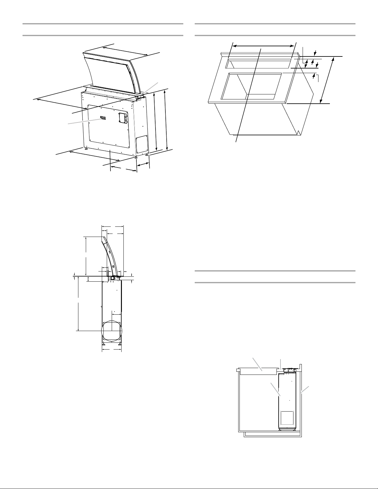
Product Dimensions Cabinet Dimensions
A
B
C
D
E
G
I
H
F
A
B
C
D
E
F
G
H
I
J
K
L
M
A
B
C
D*
E
F
A
B
C
D
A. 39
⁷⁄₁₆
" (100.2 cm)
¹¹⁄₁₆
" (17.0 cm)
B. 6
C. 2" (5.1 cm) min. to back wall
D. Minimum countertop depth. See IMPORTANT*.
E. 3½" (8.9 cm) min.
A. 35¼" (89.5 cm)
B. Infrared remote sensor
¹⁵⁄₁₆
" (76.0 cm)
C. 29
D. 33" (83.8 cm) min.,
38½" (97.8 cm) max.
E. 9¼" (23.5 cm)
F. Centerline of bottom vent area
G. 39¼" (99.7 cm)
H. Remote up/down switch
connector
I. 40¾" (103.5 cm)
*IMPORTANT: Cabinet and countertop depths are determined by
the cooking appliances to be used with this downdraft vent
system.
NOTES:
■ See appliance manufacturer’s installation instructions for
■ Exterior-mounted blower systems connect with 10" (25.4 cm)
■ Use the dimensions for the vent system cutout location that
F. Centerline of cooktop and downdraft ventilation system
cooking appliances dimensional cutout requirements.
round vent. The cutout locations for this vent system will
depend upon your specific installation.
apply to your installation.
Countertop Cutout Dimensions
IMPORTANT: Countertops with a bull-nosed front edge are not
recommended for these installations.
Cabinet and Countertop depths requirements may be deeper
than 38" (96.5 cm). This depth is determined by the cooking
appliances being installed with this downdraft vent system.
To avoid mistakes, it is recommended that the cooktop and vent
cutouts be drawn on the countertop before making any cutouts.
See cooking appliance Installation Instructions for complete
cutout dimensions, location dimensions and installation details.
H. 1
⁵⁄₈
" (4.1 cm)
I. 4
⁵⁄₈
" (11.7 cm)
J. 9¼" (23.5 cm)
K. 26" (66.0 cm)
typical, both sides
⁷⁄₁₆
" (6.2 cm)
L. 2
M.
⁵⁄₁₆
" (0.8 cm)
A. Cooktop
B. Downdraft vent system
C. Countertop
D. Back wall of cabinet
A. 18½" (47.0 cm)
B. 2½" (6.4 cm)
³⁄₈
C. 10
⁷⁄₈
" (20.0 cm)
D. 7
E. 3" (7.6 cm)
F. ½" (1.3 cm)
⁵⁄₁₆
" (3.3 cm)
G. 1
" (26.4 cm)
6

Electrical Requirements
Observe all governing codes and ordinances.
Ensure that the electrical installation is adequate and in
conformance with National Electrical Code, ANSI/NFPA 70 (latest
edition), or CSA Standards C22.1-94, Canadian Electrical Code,
Part 1 and C22.2 No. 0-M91 (latest edition) and all local codes
and ordinances.
If codes permit and a separate ground wire is used, it is
recommended that a qualified electrician determine that the
ground path is adequate.
A copy of the above code standards can be obtained from:
National Fire Protection Association
1 Batterymarch Park
Quincy, MA 02169-7471
CSA International
8501 East Pleasant Valley Road
Cleveland, OH 44131-5575
■ A 120 volt, 60 Hz., AC only, 15-amp, fused electrical circuit is
required.
■ If the house has aluminum wiring, follow the procedure
below:
1. Connect a section of solid copper wire to the pigtail
leads.
2. Connect the aluminum wiring to the added section of
copper wire using special connectors and/or tools
designed and UL listed for joining copper to aluminum.
Follow the electrical connector manufacturer's recommended
procedure. Aluminum/copper connection must conform with
local codes and industry accepted wiring practices.
■ Wire sizes and connections must conform with the rating of
the appliance as specified on the model/serial rating plate.
The model/serial plate is located on the front of the downdraft
vent.
■ Wire sizes must conform to the requirements of the National
Electrical Code, ANSI/NFPA 70 (latest edition), or CSA
Standards C22. 1-94, Canadian Electrical Code, Part 1 and
C22.2 No. 0-M91 (latest edition) and all local codes and
ordinances.
Venting Requirements
IMPORTANT: Make sure there is proper clearance within the wall
or floor before making exhaust vent cutouts.
■ Use heavy (rigid) metal vent.
■ Venting system must terminate to the outside.
■ Do not terminate the vent system in an attic or other enclosed
area.
■ Do not use 4" (10.2 cm) laundry-type wall caps.
■ Do not install 2 elbows together.
■ Do not use plastic or metal foil vent.
■ The length of vent system and number of elbows should be
kept to a minimum to provide efficient performance.
■ Use no more than three 90° elbows
■ Make sure there is a minimum of 24" (61 cm) of straight vent
between the elbows if more than one elbow is used.
■ Use clamps or duct tape to seal all joints in the vent system.
■ Use caulking tape to seal the exterior wall or floor opening
around cap.
■ Do not cut joist or stud. If vent cutout falls over a joist or stud,
a supporting frame must be constructed.
Flexible metal vent is not recommended. If it is used, calculate
each foot of flexible vent as 2 ft (0.6 m) of rigid metal vent.
Flexible elbows count twice as much as standard elbows.
Recommended Vent System Length:
The vent system length should not exceed the maximum lengths
listed in the Maximum Length of Vent System chart. See
“Calculating Vent System Length” in the “Venting Methods”
section in the Installation Instructions for the interior- or exteriormounted vent motor.
Cold Weather Installations
An additional back draft damper should be installed to minimize
backward cold air flow and a thermal break should be installed to
minimize conduction of outside temperatures as part of the vent
system. The damper should be on the cold air side of the thermal
break.
The break should be as close as possible to where the vent
system enters the heated portion of the house.
Makeup Air
Local building codes may require the use of makeup air systems
when using ventilation systems greater than specified CFM of air
movement. The specified CFM varies from locale to locale.
Consult your HVAC professional for specific requirements in your
area.
See the “Accessories” section for information on ordering
optional kits.
7

INSTALLATION INSTRUCTIONS
A
A
A
WARNING
Excessive Weight Hazard
Use two or more people to move and install
downdraft vent.
Failure to do so can result in back or other injury.
NOTE: Your downdraft vent requires you to purchase an in-line
(external type) blower motor system. See “Blower Motor System”
in the “Accessories” section.
CAUTION: To reduce the risk of fire and electrical shock, install
the downdraft only with remote blower systems that are sold by
Whirlpool Corporation. Model numbers UXI0600DYS (600 cfm)
and UXI1200DYS (1200 cfm).
Venting M eth ods
Determine which venting method is best for your application.
Vent system can terminate through the wall or roof. A wall cap or
roof cap is required.
NOTES:
■ Venting through a concrete slab is not recommended.
■ The in-line blower motor system must be placed in an
enclosed area and can be located in a utility room, basement,
crawl space or attic. Observe all governing codes and
ordinances.
■ 10" (25.4 cm) round vent duct is required for connections to
the retractable downdraft vent system outlet cover and the
remote blower motor inlet and outlet covers. 10" (25.4 cm)
round vent duct is recommended for the retractable
downdraft vent system with remote blower motor system.
Transitioning to different size ducting will reduce the
efficiency of the retractable downdraft vent system.
Calculating Vent System Length
It is recommended that you use round vent instead of rectangular
vent, especially if elbows are required. If rectangular vent is
required, it should be transitioned to 10" (25.4 cm) round vent as
soon as possible.
Maximum Length of Vent System
Vent Length
10" (25.4 cm) round 60 ft (18.3 m)
To calculate the length of the system you need, add the
equivalent feet (meters) for each vent piece used in the system.
Vent Piece 10" (25.4 cm) Round
45° elbow 2.5 ft
90° elbow 5.0 ft
The maximum equivalent vent lengths of 10" (25.4 cm) round
vents - 60 ft (18.3 m).
2 - 90° elbows = 10.0 ft (3 m)
10 ft (3 m) straight = 10.0 ft (3 m)
Length of 10" (25.4 cm)
system
(0.8 m)
(1.5 m)
= 20 ft (6 m)
A. Three options for exhaust direction to
remote blower motor system
8
NOTE: The remote blower system requires a separate wiring
cable that should be installed at the same time the vent work is
installed.
Downdraft Vent System Preparation
NOTE: It is easiest to install this unit before the countertop is
installed. The preferred method of installation is inserting this unit
into the cabinet and then placing the countertop over it.
1. Place cardboard or similar material on top of a flat surface
where you can easily assemble the downdraft vent system.
2. Open the wooden crate by removing the screws holding the
top in position.
3. Remove the parts packages from the wood crate and set
aside.
4. Remove the downdraft vent system from the wooden crate
and place on assembly surface with the access panel/
junction box facing up.
5. Measure the distance “E” from the cabinet floor to the top of
A
B
C
D
E
A
B
C
D
E
F
A
B
the countertop.
NOTE: Dimension “E” must be 32⁵⁄₈" (82.9 cm) minimum or
the cabinet floor will have to be removed to allow the hood
feet to rest on the floor.
Vent Collar and Vent Transition Installation
When installed in a cabinet, the vent system can exhaust through
the bottom, right side, or left side of the vent box. The downdraft
vent system is shipped ready to vent out of the bottom of the
vent box. If this is not the desired exhaust direction, complete the
following steps.
A. Cooktop
B. Downdraft vent system
C. Countertop
D. Back wall of cabinet
E. Cabinet floor to top of
countertop
6. Screw in the 4 feet so that the overall height of the unit from
the feet to the top is approximately 1" (2.5 cm) less than
dimension “E.”
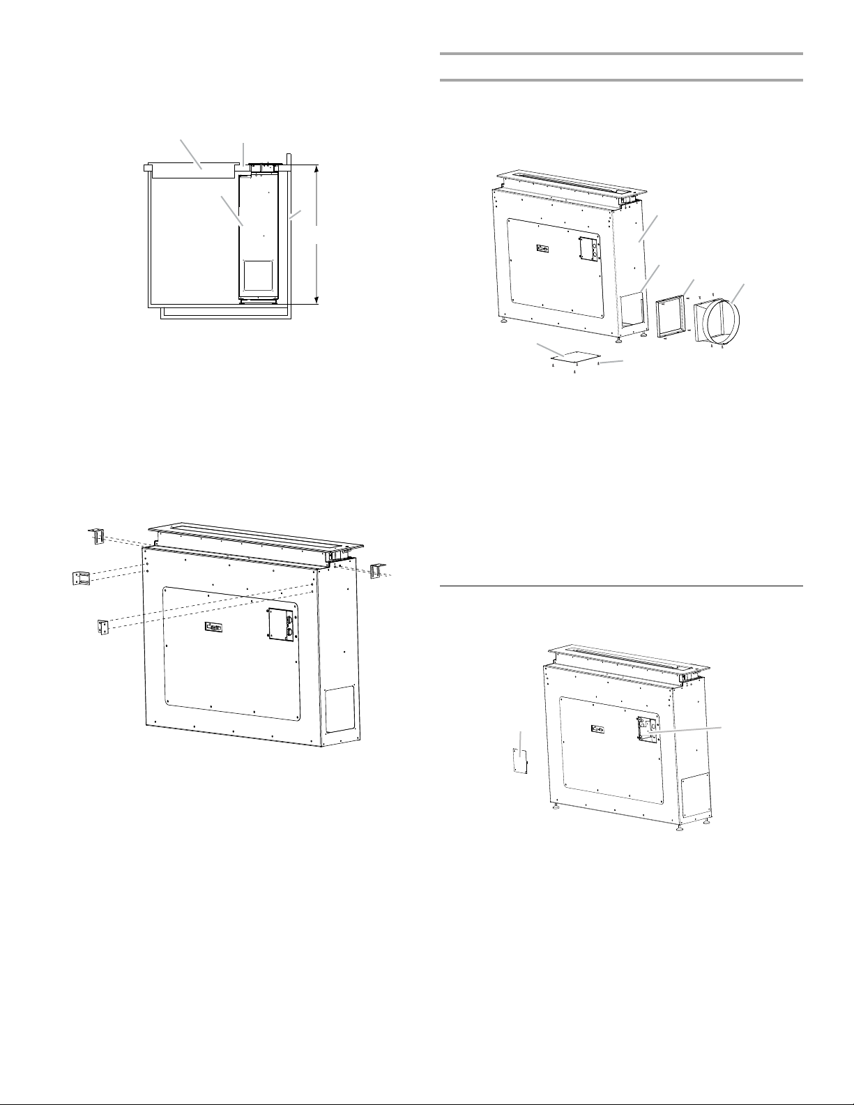
7. Install the right and left undercounter mounting brackets to
the vent box. The mounting brackets can be mounted to the
front or rear face of the downdraft for attachment to the
cabinets, or to each side face for attachment to the
countertop. (See the following illustration.) Loosely secure the
screws in the slots with the 4 - 4.9 x 12 mm machine screws.
A. Vent box
B. Exhaust port
C. Vent collar mounting frame
D. Vent transition
E. Cover plate
F. S c re w s
1. Remove cover plate from the desired exhaust port location.
2. Remove vent collar mounting frame from bottom exhaust
port location.
3. Install the vent collar mounting frame to the desired vent box
exhaust port using the 4 screws.
4. Install the vent translation to the vent collar mounting frame
using 4 - 4.9 x 12 mm screws.
5. Install the cover plate to the exhaust port that the vent collar
mounting frame was removed from, using the 4 screws.
Install Downdraft Vent System
1. Remove the 3 screws from the terminal box cover.
A. Terminal box cover
B. Knockout
2. Remove the knockout from the front panel and install a ½"
(1.3 cm) UL listed or CSA approved conduit connector.
3. Using 2 or more people, insert the downdraft vent into the
cabinet. Position the downdraft vent so that it is
approximately centered below the countertop cutout
location.
4. If the countertop is not already installed, follow the directions
for the countertop installation to place it onto the cabinets.
5. Using a ½" wrench, screw out the feet on the vent box to
raise the top of the unit until it is flush with the top surface of
the countertop.
9

6. Center and level the top of the downdraft vent left to right and
A
B
C
D
E
WARNING
Excessive Weight Hazard
Use two or more people to move and install in-line
blower motor system.
Failure to do so can result in back or other injury.
A
B
C
D
front to back. Use a ⁹⁄₁₆" wrench to lock the feet into position
with the locknuts.
7. Secure the hood vent box to the countertop or cabinet sides
with the undercounter mounting brackets attached earlier at
the desired location. If mounting to a countertop, use screws
or mounting method recommended for the specific type of
countertop.
8. Install the top frame support, using the 12 - 3.9 x 9 mm
flat-head screws.
9. Install the top frame.
A. 12 Flat-head screws
B. Top frame
C. Guide pins in top frame
D. Hole for top frame guide pins
E. Top frame support
Prepare the In-line Blower System
1. Using 2 or more people, move the in-line blower motor
system to the mounting location.
2. Remove the 10 screws from the front cover of the in-line
blower motor housing and set them aside.
3. Remove the front cover of the in-line blower motor housing
and set it aside.
NOTE: To make the blower motor housing easier to mount,
the blower motor assembly can be removed. If you do not
want to remove the blower motor assembly, proceed to
“Install In-line Blower System” in this section.
4. Disconnect the motor electrical plug from the blower motor
assembly.
5. Remove the screws that secure the blower motor assembly
to the in-line blower housing and set them aside.
6. Pull the spring clip to release the blower motor assembly.
Remove the blower motor assembly from the housing and
place it on a covered surface.
Install Downdraft Vent In-Line (External
Type) Blower Motor
Prepare for Mounting the In-Line Blower System
The in-line blower system must be fastened to a secure structure
of the roof, ceiling, wall, floor, or new or existing frame
construction. The 4 holes on either the inlet (bottom) side or the
outlet (top) side of the blower must be used to mount the in-line
blower system to the structure.
NOTE: The mounting hole locations must span the studs.
Additional stud framing may be required. Plywood may be used
to span open areas between ceiling or floor joists or roof rafters
to aid installation. This structure must be strong enough to
support the weight of the in-line blower system (50 lb
[22.7 kg] min).
A. Front cover
B. Blower mounting screws
C. Spring clip
D. Motor electrical plug
10
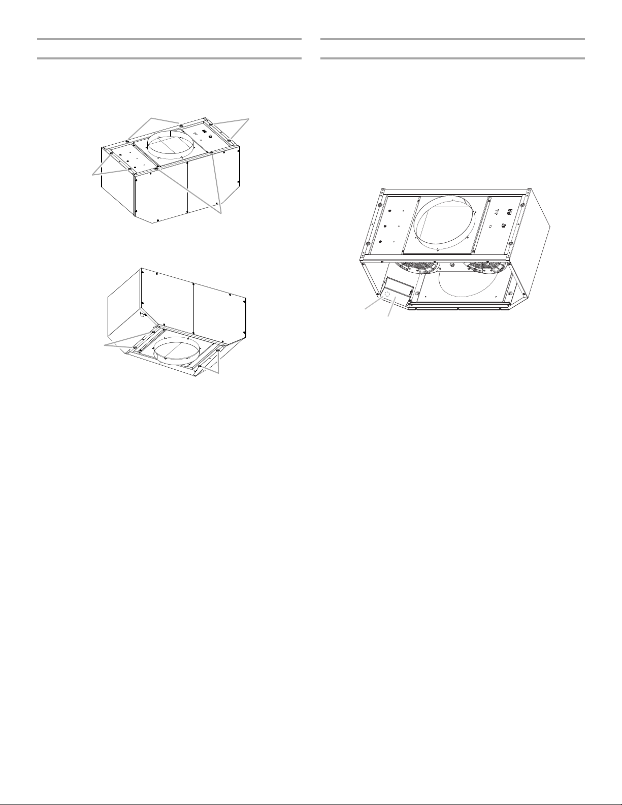
Install In-line Blower System
A
A
A
A
A
A
A
B
Complete Preparation
NOTE: The blower motor housing can be mounted using 4 holes
from either the inlet side or the outlet side of the blower.
Outlet Side
A. Mounting holes
Inlet Side
1. Determine and make all necessary cuts for the vent system.
IMPORTANT: When cutting or drilling into the floor, ceiling or
wall, do not damage electrical wiring or other hidden utilities.
2. Determine the location where the ¹⁄₂" (1.3 cm) wiring conduit
will be routed through the floor, ceiling or wall between the inline blower and the downdraft vent.
3. Drill a 1¹⁄₄" (3.2 cm) hole at this location.
4. Locate the electrical terminal boxes in the in-line blower
housing and downdraft vent. Remove the terminal box covers
and set the covers and screws aside.
A. Electrical terminal box
B. Electrical knockout
A. Mounting holes
1. Position the in-line blower motor housing in its mounting
location and mark the 4 mounting hole locations.
2. Drill 4 mounting pilot holes using a ³⁄₁₆" (4.8 mm) drill bit.
3. Attach the in-line blower motor housing to the mounting
location with 4 - 6 x 80 mm mounting screws and washers.
4. If it is removed, reinstall the blower motor assembly and
secure it with the screws previously removed.
5. If it is removed, reattach the motor electrical plug to the
connector on the blower motor assembly.
5. Remove the electrical knockout from the in-line blower
housing and downdraft vent to prepare for the installation of
the UL listed or CSA approved ¹⁄₂" (1.3 cm) wiring conduit and
conduit connector.
6. With the downdraft vent mounted, run the ¹⁄₂" (1.3 cm) wiring
conduit between the in-line blower motor housing and the
downdraft vent. Pull enough ¹⁄₂" (1.3 cm) wiring conduit to
allow for easy connection to the terminal boxes in the in-line
blower housing and downdraft vent.
7. Run the six 18 AWG wires through the ¹⁄₂" (1.3 cm) wiring
conduit and conduit connectors and into the terminal boxes
on the in-line blower housing and downdraft vent. Leave
enough wire length in each terminal box to make the wiring
connections.
8. Install the conduit connectors and conduit to the in-line
blower housing and downdraft vent electrical terminal boxes.
9. Connect the vent system to the downdraft vent and in-line
blower system and seal all joints with clamps.
11

Make Electrical Connections for In-Line Blower Motor System
WARNING
Electrical Shock Hazard
Disconnect power before servicing.
Replace all parts and panels before operating.
Failure to do so can result in death or electrical shock.
A
B
C
D
E
F
G
H
I
J
WARNING
Electrical Shock Hazard
Electrically ground blower.
Connect ground wire to green and yellow ground wire
in terminal box.
Failure to do so can result in death or electrical shock.
A
G
F
E
D
C
B
J
I
H
Electrical Connection Inside In-line Blower System
1. Disconnect power.
2. Connect the wires from the wiring conduit to the wires from
the motor electrical plug cable inside the in-line blower
housing terminal box.
7. Use UL listed wire connectors and connect the gray wires (G)
together.
8. Connect the green (or yellow/green) ground wire to the
green/yellow ground wire (H) in the terminal box using UL
listed wire connectors.
9. Reinstall the in-line blower terminal box cover and screw.
10. Reinstall the front cover of the in-line blower housing and
secure it with 10 mounting screws.
A. UL listed or CSA approved
¹⁄₂
" (1.3 cm) wiring conduit
B. UL listed wire connectors
C. Black wires
D. White wires
E. Red wires
F. Blue w i r e s
G. Gray wires
H. Green (or yellow/green) and
green/yellow wires
I. Motor electrical plug cable
J. UL listed or CSA approved
¹⁄₂
" (1.3 cm) strain relief
3. Use UL listed wire connectors and connect the black wires
(C) together.
4. Use UL listed wire connectors and connect the white wires
(D) together.
5. Use UL listed wire connectors and connect the red wires (E)
together.
6. Use UL listed wire connectors and connect the blue wires (F)
together.
Electrical Connection Inside Downdraft Vent Between Inline Blower System and Downdraft Vent
NOTE: Discard the 6-wire connector assembly supplied with the
in-line blower motor system.
1. With the downdraft vent mounted, locate the terminal block
inside the downdraft vent junction box.
2. Using a small ¹⁄₈" flat-blade screwdriver, loosen the screw in
the 5 open spots of the terminal block.
3. Connect the same color wire from the in-line blower wiring
conduit to the same color wires on the terminal block in the
downdraft vent junction box (black to black, white to white,
etc.).
4. Tighten the terminal block screws.
12
A.Downdraft vent junction box
B. Black wires
C. Gray wires
D. Red wires
E. White wires
F. Green (or yellow/green)
and green/yellow wires
G. Terminal block
H. Power supply cord
I. ½" (1.3 cm) UL listed or CSA
approved wiring conduit
from in-line blower system
J. ½" (1.3 cm) UL listed or CSA
approved conduit connector
 Loading...