

Jenn-Air SCS3004GV Installation Instructions
15" (38.1 cm)
Part No. 4455834 Rev. A
Installation Instructions
IMPORTANT:
Installer: Leave Installation
Instructions with the homeowner.
Homeowner: Keep Installation
Instructions for future reference.
Save Installation Instructions for local
electrical inspector’s use.
Write down the model and serial
numbers before installing cooktop.
Both numbers are on the model/serial
rating plate, located on the underside of
the cooktop burner box.
Model # _______________________________
Serial #________________________________
IMPORTANT:
Read and save these
instructions.
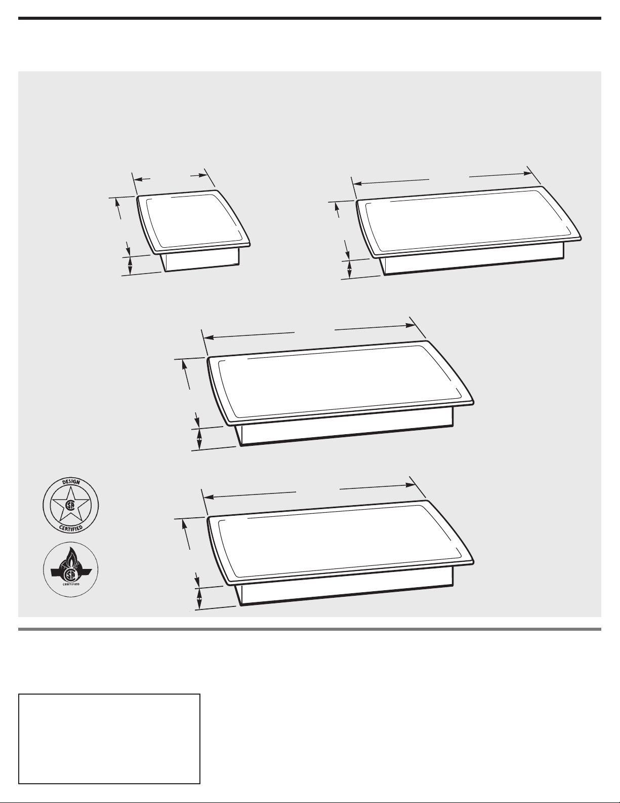
Gas Built-in Cooktops
30" (76.2 cm)
36" (91.4 cm)
42" (106.7 cm)
15"
(38.1 cm)
30"
(76.2 cm)
21"
(53.3 cm)
2-7/8"
(7.3 cm)
21"
(53.3 cm)
2-7/8"
(7.3 cm)
2-7/8"
(7.3 cm)
36"
(91.4 cm)
21"
(53.3 cm)
2-7/8"
(7.3 cm)
43"
(109.2 cm)
21"
(53.3 cm)
Before you start...
Tools needed for installation:
IMPORTANT: Observe all governing
codes and ordinances.
NOTE:This cooktop is manufactured for
use with Natural gas*. To convert to
L.P./Propane gas, see instructions in the
Gas Conversion Kit provided in literature
package.
Proper gas supply connection must be
available. See “Gas supply
requirements,” Page 4.
Proper installation is your responsibility.
Have a qualified technician install this
cooktop.
Make sure you have everything
necessary for correct installation. It is the
responsibility of the installer to comply
with the installation clearances specified
on the model/serial rating plate. The
model/serial rating plate can be found on
the underside of the cooktop burner box.
Check location where cooktop will be
installed. The location should be away
from strong draft areas, such as
windows, doors and strong heating vents
or fans.
Do not obstruct flow of combustion and
ventilation air.
All openings in the wall or floor where
the cooktop is to be installed must be
sealed.
When installing a cooktop under existing
cabinets and the installation does not
meet the minimum cabinet clearances,
install a range hood above the cooktop
to avoid burn hazards.
Electrical ground is required. See
“Electrical Requirements,” Pages 4-5.
It is the customer’s responsibility:
• To contact a qualified electrical installer.
• To assure that electrical installation is
adequate and in conformance with
National Electrical Code, ANSI/NFPA
70 — latest edition**, or Canadian
Electrical Code, C22.1 -1982 and C22.2
No. 01982 (or latest edition)*** and all
local codes and ordinances.
Copies of the standards listed may be
obtained from:
**National Fire Protection Association
One Batterymarch Park
Quincy, Massachusetts 02269
***CSA International
8501 East Pleasant Valley Rd.
Cleveland, OH 44131-5575
WARNING: If the
information in this manual
is not followed exactly, a
fire or explosion may result
causing property damage,
personal injury or death.
— Do not store or use
gasoline or other
flammable vapors and
liquids in the vicinity of
this or any other
appliance.
— WHAT TO DO IF YOU
SMELL GAS
• Do not try to light any
appliance.
• Do not touch any
electrical switch.
• Do not use any phone in
your building.
• Immediately call your
gas supplier from a
neighbor’s phone. Follow
the gas supplier’s
instructions.
• If you cannot reach your
gas supplier, call the fire
department.
— Installation and service
must be performed by a
qualified installer, service
agency or the gas
supplier.
2
You can be killed or seriously injured if
you don’t follow instructions.
All safety messages will tell you what
the potential hazard is, tell you how to
reduce the chance of injury, and tell
you what can happen if the
instructions are not followed.
DANGER
Your safety and the safety of others are
very important.
We have provided many important
safety messages in this manual and on
your appliance. Always read and obey
all safety messages.
This is the safety alert symbol.
This symbol alerts you to
potential hazards that can kill
or hurt you and others.
All safety messages will follow the
safety alert symbol and either the word
“DANGER” or “WARNING”. These
words mean:
You can be killed or seriously injured
if you don’t immediately follow
instructions.
WARNING
*Exception: Model KGCR055 is
manufactured for use with LP gas only
.
Assemble the required tools and parts
before starting installation. Read and
follow the instructions provided with any
tools listed here.
• ruler or tape measure
• flat-blade screwdriver
• pencil
• pliers
Minimum distance to
combustible surface
above countertop
3
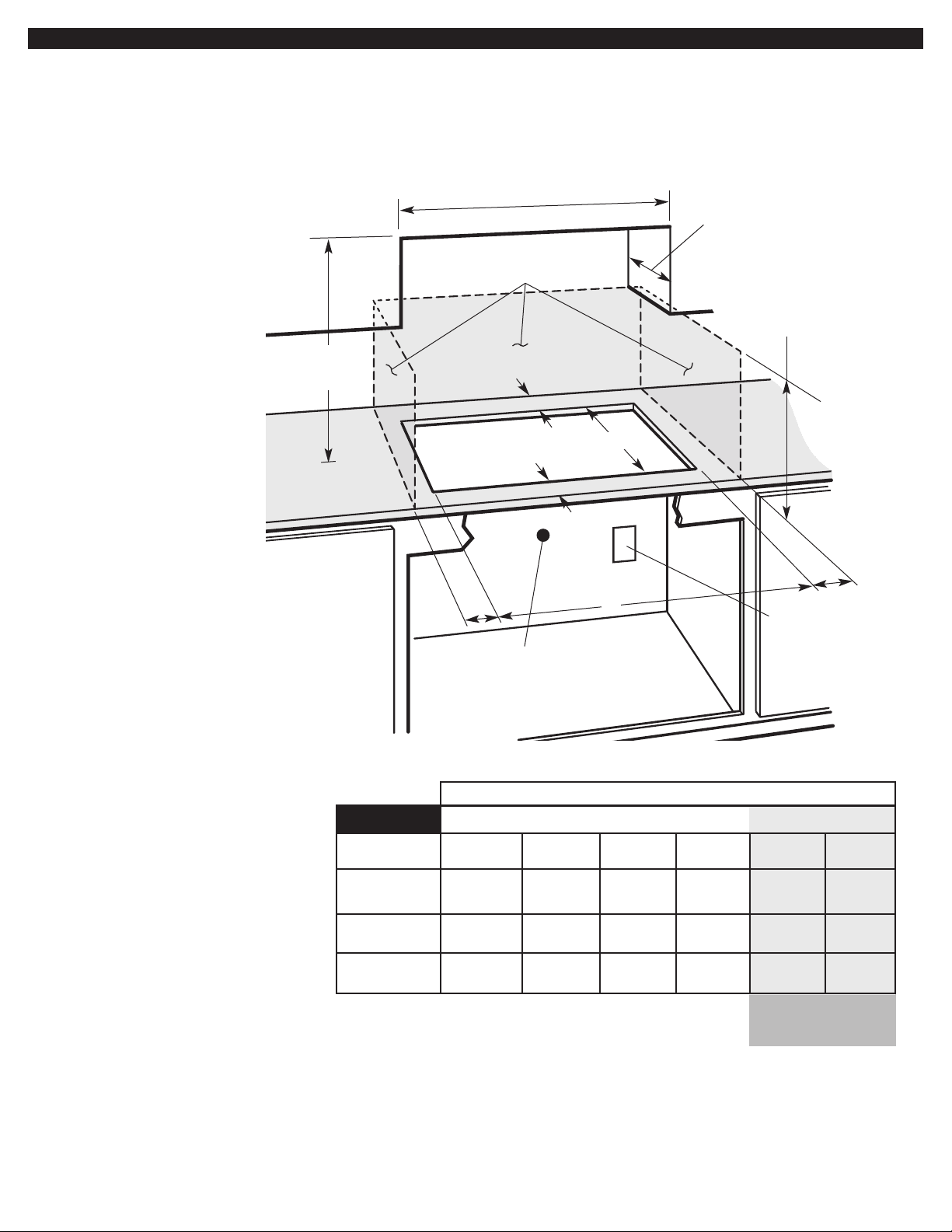
Countertop opening dimensions that are
shown must be used. Given dimensions
provide required clearances.
Replacement instructions: Use minimum
dimensions given.
Mobile home installation: The installation
of this cooktop must conform to
the Manufactured Home
Construction and Safety
Standards, Title 24 CFR, Part 3280
(formerly the Federal Standard for
Mobile Home Construction and
Safety; Title 24 HUD part 280); or
when such standard is not
applicable, the Standard for
Manufactured Home Installations
(Manufactured Home Sites,
Communities and Setups), ANSI
A225.1 — latest edition**, or with
local codes.
In Canada, the installation of this
cooktop must conform with the
current standards CAN/CSA-Z240
— latest edition***, or with local
codes.
NOTE: If cabinet has a drawer, a 4" (10.2 cm) depth clearance from the top of
the countertop to the top of the drawer (or other obstruction) in base cabinet is
required. The drawer depth may need to be shortened to avoid interfering with
the regulator.
min.
15" 13-3/4" 19" 15" 2-1/8" 2-7/8" 5-5/8"
(38.1 cm) (34.9 cm) (48.3 cm) (38.1 cm) (5.4 cm) (7.3 cm) (14.3 cm)
30" 29" 19" 30" 2-1/8" 2-7/8" 5-5/8"
(76.2 cm) (73.7 cm) (48.3 cm) (76.2 cm) (5.4 cm) (7.3 cm) (14.3 cm)
36" 35-1/4" 19" 36" 2-1/8" 2-7/8" 5-5/8"
(91.4 cm) (89.5 cm) (48.3 cm) (91.4 cm) (5.4 cm) (7.3 cm) (14.3 cm)
42" 42-3/4" 19" 42" 2-1/8" 2-7/8" 11-1/2"
(106.7 cm) (108.6 cm) (48.3 cm) (106.7 cm) (5.4 cm) (7.3 cm) (28.4 cm)
Cooktop width
Grounded outlet –
Locate within 24"
(61 cm) of right
rear corner of
cutout.
Gas line opening –
Wall: anywhere 5" (12.7 cm)
below underside of countertop.
Cabinet floor: anywhere within
6" (15.2 cm) of rear wall is
recommended.
Do not seal cooktop
to countertop.
24" (61 cm) min. –
deep countertop is
required.
13" (33 cm)
recommended
upper cabinet
depth
See NOTE*
for minimum
clearances.
combustible area
above
countertop
*NOTE: 24" (61 cm) min. clearance if bottom of wood or
metal cabinet is protected by not less than 1/4" (0.6 cm)
flame retardant millboard covered with not less than No.
28 MSG sheet steel, 0.015" (0.04 cm) stainless steel, or
0.024"(0.06 cm) aluminum or 0.020" (0.05 cm) copper.
30" (76.2 cm) min. clearance between top of cooking
platform and bottom of unprotected wood or metal
cabinet.
Cutout dimensions/requirements
18" (45.7 cm) min.
clearance upper
cabinet to countertop
within minimum
clearances to cooktop
Illustration dimensions
Important note on base cabinet construction: After making
the countertop cutout, some installations may require
notching down the base cabinet side walls to clear the
burner box. To avoid this modification, use a base cabinet
having sidewalls wider than the cutout.
Gas supply requirements
Electrical requirements
Observe all governing codes and
ordinances.
IMPORTANT: Cooktop must be connected
to a regulated gas supply.
A.This installation must conform
with local codes and ordinances. In the
absence of local codes, installations must
conform with American National
Standard, National Fuel Gas Code ANSI
Z223.1 — latest edition** or CANI —
B149.1 or 2***.
D.Provide a gas supply line of 3/4"
rigid pipe to the cooktop location. A
smaller size pipe on long runs may result
in insufficient gas supply. Pipe-joint
compounds, suitable for use with L.P.
gas, must be used. With L.P. gas, piping
or tubing size can be 1/2" minimum. L.P.
gas suppliers usually determine the size
and materials used on the system.
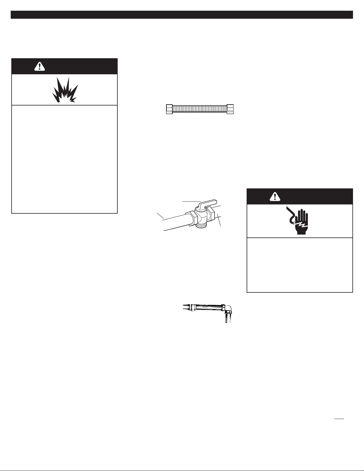
E.If local codes permit, a new AGA
or CSA design-certified, 4-5 foot (1.2-1.5
m) long, 1/2" or 3/4" I.D., flexible metal
appliance connector is recommended for
connecting this cooktop to the gas supply
line. Do not kink or damage the flexible
connector when moving the cooktop. The
pressure regulator has 3/8" female pipe
threads. You will need to determine the
fittings required, depending on the size of
your gas supply line, flexible metal
connector and shutoff valve.
F.The supply line shall be equipped
with an approved shutoff valve. This
valve should be located in the same
room as the cooktop and should be in a
location that allows ease of opening and
closing. Do not block access to the
shutoff valve. The valve is for turning on
or shutting off gas to the appliance.
to cooktop
shutoff valve
“open” position
gas supply
line
G.If rigid pipe
is used as a gas
supply line, a combination of pipe
fittings must be used to obtain an in-line
connection to the cooktop. All strains
must be removed from the supply and
fuel lines so cooktop will be level and in
line.
H.The regulator must be checked at
a minimum 1-inch (2.5 cm) water column
above the set pressure. The inlet pressure
to the regulator should be as follows for
operation and checking the regulator
setting:
NATURAL GAS:
Set pressure 4 inches (10.2 cm).
Supply pressure 7-14 inches (17.8 cm
to 35.5 cm) maximum.
L.P. GAS:
Minimum pressure 10 inches (25.4 cm).
Supply pressure 14 inches (35.5 cm).
I.Line pressure testing:
Testing above 1/2 psi (3.5 kPa)
(14 inches (35.6 cm)) W.C. (gauge)
The cooktop and its individual shutoff
valve must be disconnected from the gas
supply piping system during any
pressure testing of that system at test
pressures greater than 1/2 psig (3.5kPa).
Testing below 1/2 psi (3.5 kPa) (14 inches
(35.6 cm)) W.C. (gauge) or lower
The cooktop must be isolated from the
gas supply piping system by closing its
individual manual shutoff valve during
any pressure testing of the gas supply
piping system at test pressures equal to
or less than 1/2 psig (3.5 kPa).
A 120-volt, 60-Hz, AC-only, 15-ampere,
fused electrical supply is required. A
time-delay fuse or circuit breaker is
recommended. It is recommended that a
separate circuit serving only this
appliance be provided.
*Exception: Model KGCR055 is
manufactured for use with L.P. gas only.
**National Fire Protection Association
One Batterymarch Park
Quincy, Massachusetts 02269
***CSA International
8501 East Pleasant Valley Rd.
Cleveland, OH 44131-5575
If codes permit and a separate ground
wire is used, it is recommended that a
qualified electrician determine that the
ground path is adequate.
Check with a qualified electrician if you
are not sure whether the cooktop is
properly grounded.
Do not ground to a gas pipe.
4
B.Input ratings shown on the
model/serial rating plate are for
elevations up to 2,000 feet (610 m). For
elevations above 2,000 feet (610 m),
ratings are reduced at a rate of 4% for
each 1,000 feet (305 m) above sea level.
C.The cooktop is equipped for use
with natural gas*. It is design-certified by
CSA International for natural and L.P.
gases with appropriate conversion. The
model/serial rating plate, located on
the underside of the burner box, has
information on the type of gas that can be
used. If this information does not agree
with the type of gas available, check with
the local gas supplier. See Page 2 for L.P.
gas conversion instructions.
WARNING
Explosion Hazard
Use a new AGA or CSA approved gas
supply line.
Install a shutoff valve.
Securely tighten all gas connections.
If connected to LP, have a qualified
person make sure gas pressure does
not exceed 14" water column.
Examples of a qualified person
include:
licensed heating personnel,
authorized gas company
personnel, and
authorized service personnel.
Failure to do so can result in death,
explosion, or fire.
Electrical Shock Hazard
Plug into a grounded 3 prong outlet.
Do not remove ground prong.
Do not use an adapter.
Do not use an extension cord.
Failure to follow these instructions can
result in death, fire, or electrical shock.
WARNING

5
Electronic ignition systems operate
within wide voltage limits, but proper
ground and polarity are necessary. In
addition to checking that the outlet
provides 120-volt power and is correctly
grounded, the outlet must be checked by
a qualified electrician to see if it is wired
with correct polarity. A wiring diagram is
provided in the literature package.
IMPORTANT: This range is equipped with
an electronic ignition system that will not
operate if plugged into an outlet that is
not properly polarized.
This appliance, when installed, must be
electrically grounded in accordance with
local codes or, in the absence of local
codes, with the current CSA standard
C22.1. Canadian Electrical Code Part 1.
Recommended ground method
For your personal safety, this cooktop
must be grounded. This cooktop is
equipped with a 3-prong ground plug. To
minimize possible shock hazard, the cord
must be plugged into a mating 3-prong
ground-type outlet, grounded in
accordance with the National Electrical
Code ANSI/NFPA 70 latest edition** or
Canadian Electrical Code (CSA)*** —
and local codes and ordinances. If a
mating outlet is not available, it is the
personal responsibility and obligation of
the customer to have a properly
polarized and grounded, 3-prong outlet
installed by a qualified electrician.
Copies of the standards listed may be
obtained from:
**National Fire Protection Association
One Batterymarch Park
Quincy, Massachusetts 02269
***CSA International
8501 East Pleasant Valley Rd.
Cleveland, OH 44131-5575
3-prong polarized
ground-type outlet
power
supply cord
3-prong
ground plug
ground
prong
Now start…
With cooktop in kitchen.
1.Remove foam shipping blocks and
tape from cooktop. Untape power supply
cord.
2.Remove pressure regulator,
hardware package, burner grates, burner
caps, clamp brackets, and 2-1/2"(6,4 cm)
clamp screws, from shipping package.
attachment
screw
burner box
bottom
bracket (end
locations
recommended)
attachment screws
for optional front
and back location
“U” shaped spring
clip or small
diameter hole
3.Two clamp brackets are provided
to clamp the cooktop to the countertop.
Install the clamp brackets on each end of
the burner box bottom. Optional: If
cabinet construction does not provide
clearance for installing brackets at burner
box ends, install the brackets on the front
and back of the burner box bottom.
The brackets may be installed before (see
Step 3a) or after (see Step 3b) the
cooktop is placed into the cutout.
3a.If installing before the cooktop
is placed into cutout:
• Place the cooktop upside down on a
protective surface (blanket, pad).
Glass cooktops only:
Remove foam strip from literature
package. Apply foam strip around bottom
of cooktop flush with edge.
• Remove the attachment screws for the
bracket locations selected from the
bottom of the burner box.
• Use bracket mounting holes that will
allow the clamp screws (see Step 4) to
contact the countertop bottom. Attach
brackets as shown then rotate brackets
so that they do not extend beyond edge
of burner box.
• Tighten screws just enough to hold
brackets in place when cooktop is
turned over and put into cutout.
• Turn the cooktop right side up and
carefully place into the cutout.
IMPORTANT: Check that the front edge of
the cooktop is parallel to the front edge
of the countertop. Lift entire cooktop up
from cutout when repositioning cooktop
to prevent scratching the countertop.
• Loosen the screws or nuts, rotate the
brackets so that they extend beyond
edge of the burner box. Tighten screws
securely.
burner box
foam
strip
WARNING
ExcessiveWeight Hazard
Use two or more people to move and
install range.
Failure to do so can result in back or
other injury.
 Loading...