

Jenn-Air PROSTYLE JGD8348BDP Installation Instructions Manual
Triple Bay ConventionalGas _JENN-AIF_
ProstyleTM Grill Cooktop
Model JGD8348BDP _ wEsTFOURTHSTREET.NORTH.NEWTON.,A
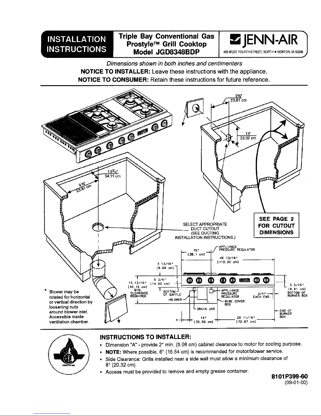
Dimensionsshowninbothinchesandcentimenters
NOTICE TO INSTALLER: Leavetheseinstructionswiththeappliance.
NOTICE TO CONSUMER: Retaintheseinstructionsforfuturereference.
j_ 23,81crn
%
SEE PAGE2
SELECTAPPROPRIATE FOR CUTOUT
DUCTCUTOUT
1" (SEEDUCTING DIMENSIONS
,i
INSTALLATIONINSTRUCTIONS.)
.__ APPLI ANCE
15o PRESSUREREGULATOR
[38.1 cm] 46 13/16" "I
3 13/16" " I [11S.90 ¢m]
_9.6B crn,- I I
,,r L, I'- ..... ,_
5 3/4 • '
,s,B,,o.1,°oco, ®® ® 14
' " _L 3 5,16.
[40.16cm] _MIN. _ I[_-- ND..___.,._ [8 41 c'_}
TT(_A- APPLIANCE '
• Blower may be CLEARANCE
BO PRESSURE 4° BOTTOMOF
CF BAFFLE 3, BURNERBOX
rotated for horizontal REQUIRED REGULATOR EACH E
"BL ERII EOVER/
orvertical directionby _ BOX
looseningnuts DRAIN JAR _ END OF
around blower inlet. -_ i:_; c / BURNER
Accessibleinside 14, 28 11/16° BOX
ventilationchamber. A _] [72.87 cm] "
__t INSTRUCTIONSTO INSTALLER:
• Dimension "A" - provide 2" rain. (5.08 cm) cabinet clearance to motor for cooling purpose.
• NOTE: Where possible, 6" (15.54 cm) is recommended for motor/blower service.
• Side Clearance: Grills installed near a side wall must allow a minimum clearance of
8" (20.32 cm).
• Access must be provided to remove and empty grease container.
8101P399-60
(09-01-00)
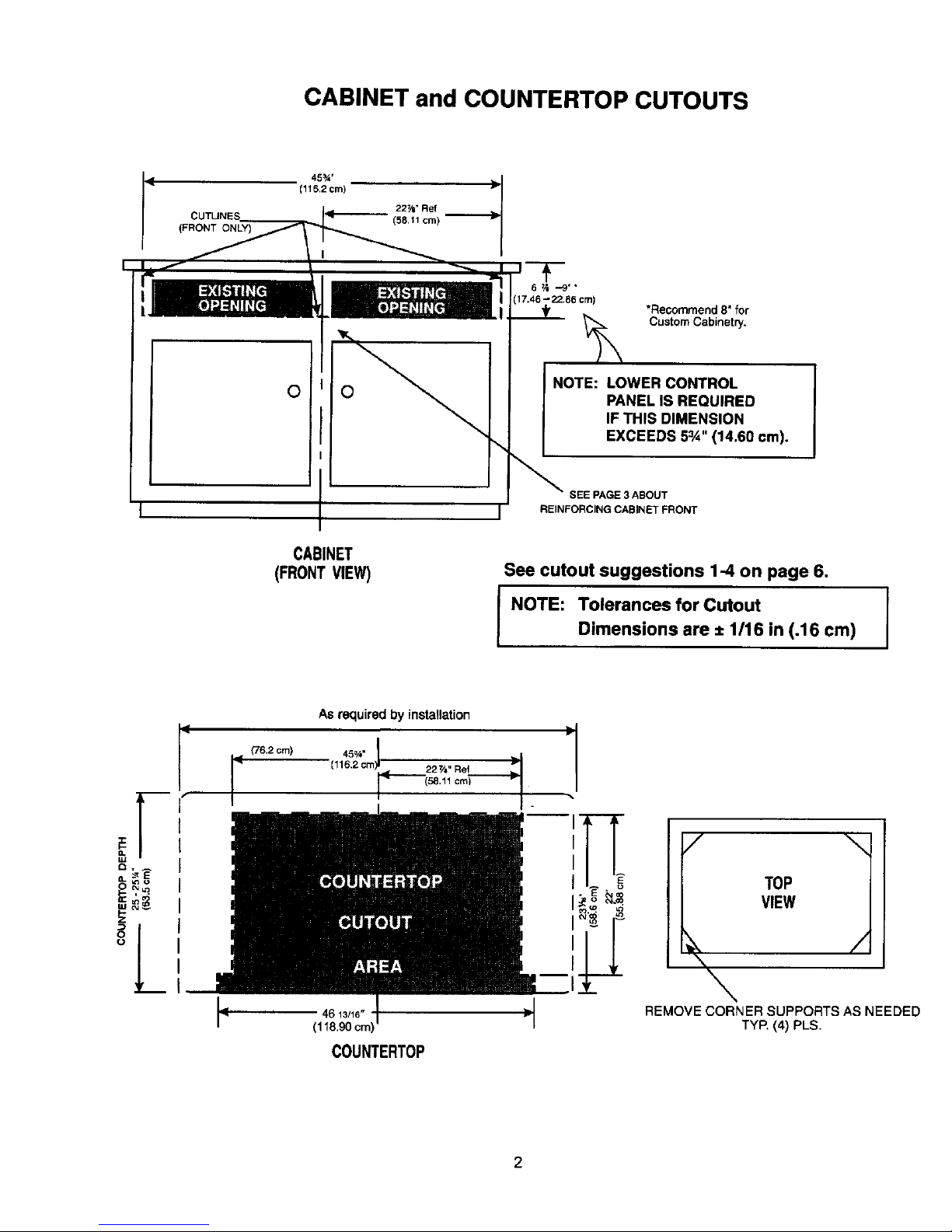
CABINETand COUNTERTOPCUTOUTS
(115.2 cm)
22_" Ref
(58,11 cm)
17.46--22.86 crn)
*Recommend8"for
CustomCabinetry.
O_ NOTE: LOWER CONTROLO
PANELIS REQUIRED
IF THIS DIMENSION
EXCEEDS 5_/_" (14.60 crn).
\
SEE PAGE 3 ABOUT
i" 1" REINFORCING CABINET FRONT
CABINET
(FRONTVIEW) See cutout suggestions 1-4on page 6.
NOTE: Tolerances for Cutout I
Dimensions are ± 1/16 in (.16 cm)
I
Asrequiredbyinstallation
(116,2cm] 227/6"Re1
(58.11crn_------
l=o I TOP
I_ _-_ VIEW
==
O
° /
'- I -- \
p 4613/16" _ REMOVECORNERSUPPORTSAS NEEDED
(118.90cm TYP.(4)PLS.
COUNTERTOP
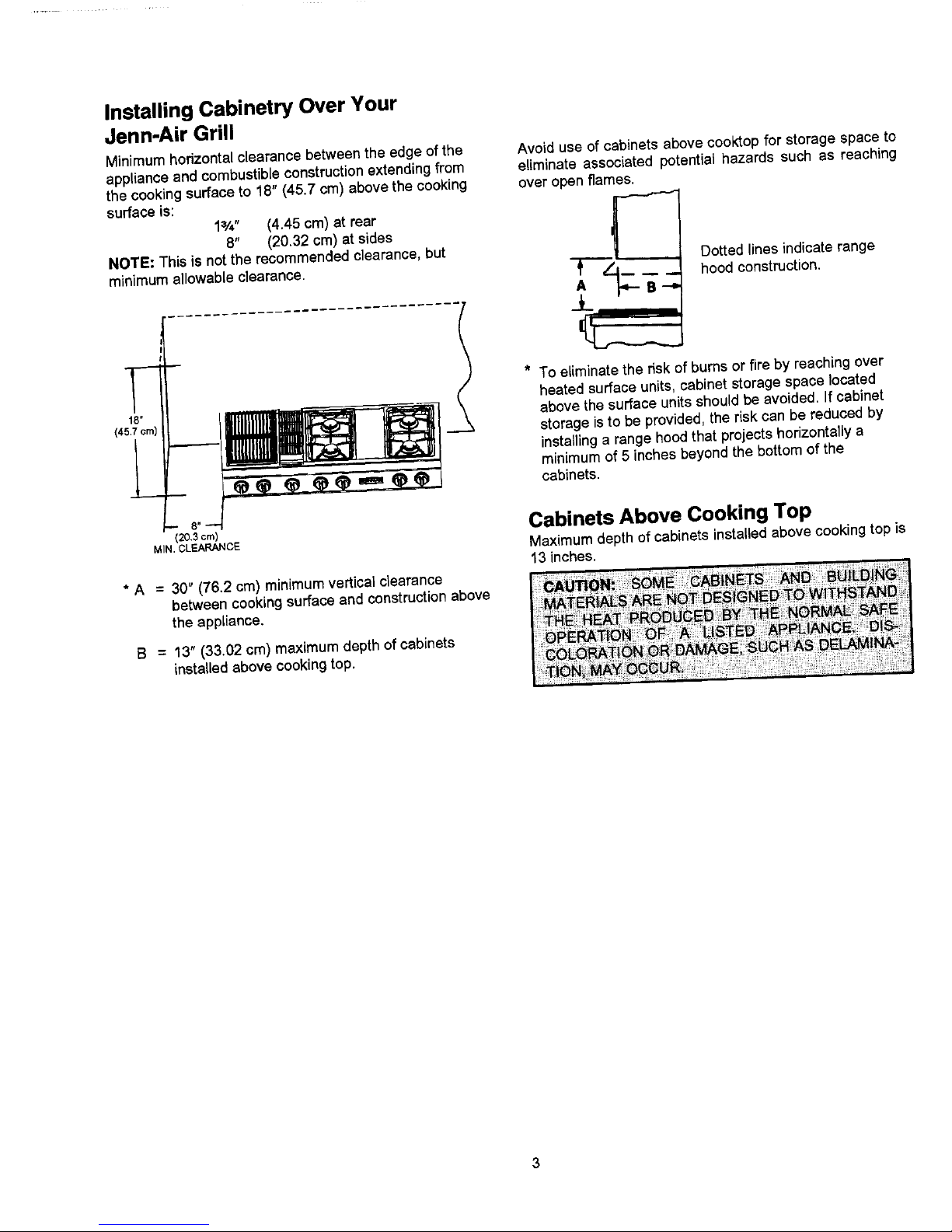
InstallingCabinetryOver Your
Jenn-AirGrill
Minimum horizontal clearancebetweentheedge of the Avoiduse of cabinetsabovecooktopfor storagespace to
applianceand combustibleconstructionextendingfrom eliminate associatedpotential hazards such as reaching
the cookingsurface to 18" (45.7 cm) above the cooking over open flames.
surfaceis:
1=/_" (4.45 cm) at rear
8" (20.32 cm) at sides
NOTE: This is not the recommended clearance, but Dotted lines indicate range
minimum al,owable clearance. ,.,_ t"--_--"l--_" __ hood construction.
* To eliminate the risk of burns or fire by reaching overheated surface units, cabinet storage space located
18, above the surface units should be avoided. If cabinet
(45,7¢m)
_ storage is to be provided, the riskcan be reduced by
installing a range hood that projects horizontally a
I_ _ _ (_ (_ _ _ (_ "_ cabinets.minimumof 5 inches beyond the bottom of the
.38"om CabinetsAboveCookingTop
MIN.CLEARANCE Maximum depth of cabinets installed above cooking top is
13 inches.
• A = 30" (76.2 cm) minimum vertical clearance
between cooking surface and construction above
the appliance.
B = 13" (33.02 cm) maximum depth of cabinets
installed above cooking top.
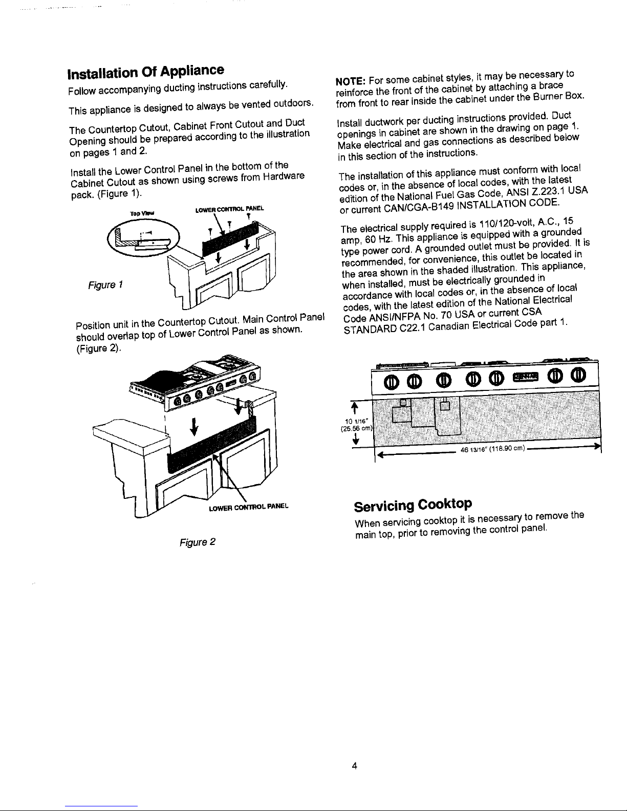
InstallationOf Appliance
Followaccompanying ducting instructions carefully. NOTE: For some cabinet styles, it may be necessary to
reinforce the front of the cabinet by attaching a brace
This appliance is designed to always bevented outdoors, from front to rearinside the cabinet under the Burner Box.
The Countertop Cutout, Cabinet Front Cutout and Duct Installductwork perducting instructions provided. Duct
Opening should be prepared according to the illustration openings in cabinet are shown in the drawing on page 1.
on pages 1 and 2. Make electricaland gas connections as described below
Installthe Lower Control Panel in the bottom of the in this section of the instructions.
Cabinet Cutout as shownusingscrews from Hardware The installationof thisappliance must conformwith local
pack. (Figure 1). codesor,in the absence of localcodes,with the latest
editionofthe NationalFuelGas Code, ANSI Z.223.1 USA
Tl_pVlml LOWER_ PANEL
or current CAN/CGA-B149 INSTALLATION CODE.
The electrical supply required is 110/120--volt,A.C., 15
amp, 60 Hz. This appliance is equipped with a grounded
type power cord. A grounded outlet must be provided. It is
recommended, for convenience, this outlet be located in
Figure 1 L. I _=,,_l II LF the area shown in the shaded illustration. This appliance,
when installed, must be electrically grounded in
accordance with local codes or, in the absence of local
codes, with the latest edition of the National Electrical
Position unitinthe Countertop Cutout. Main Control Panel Code ANSI/NFPA No. 70 USA or current CSA
should overlaptop of Lower Control Panel as shown. STANDARD C22.1 Canadian Electrical Code part 1.
(F{gure 2).
¢¢®e e,,-= ¢ ®
.EL Servicing Cooktop
When servicing cooktop it is necessary to remove the
F_gure2 main top, priorto removing the control panel.
 Loading...