

Page 1
IIISLIIENN-AI R
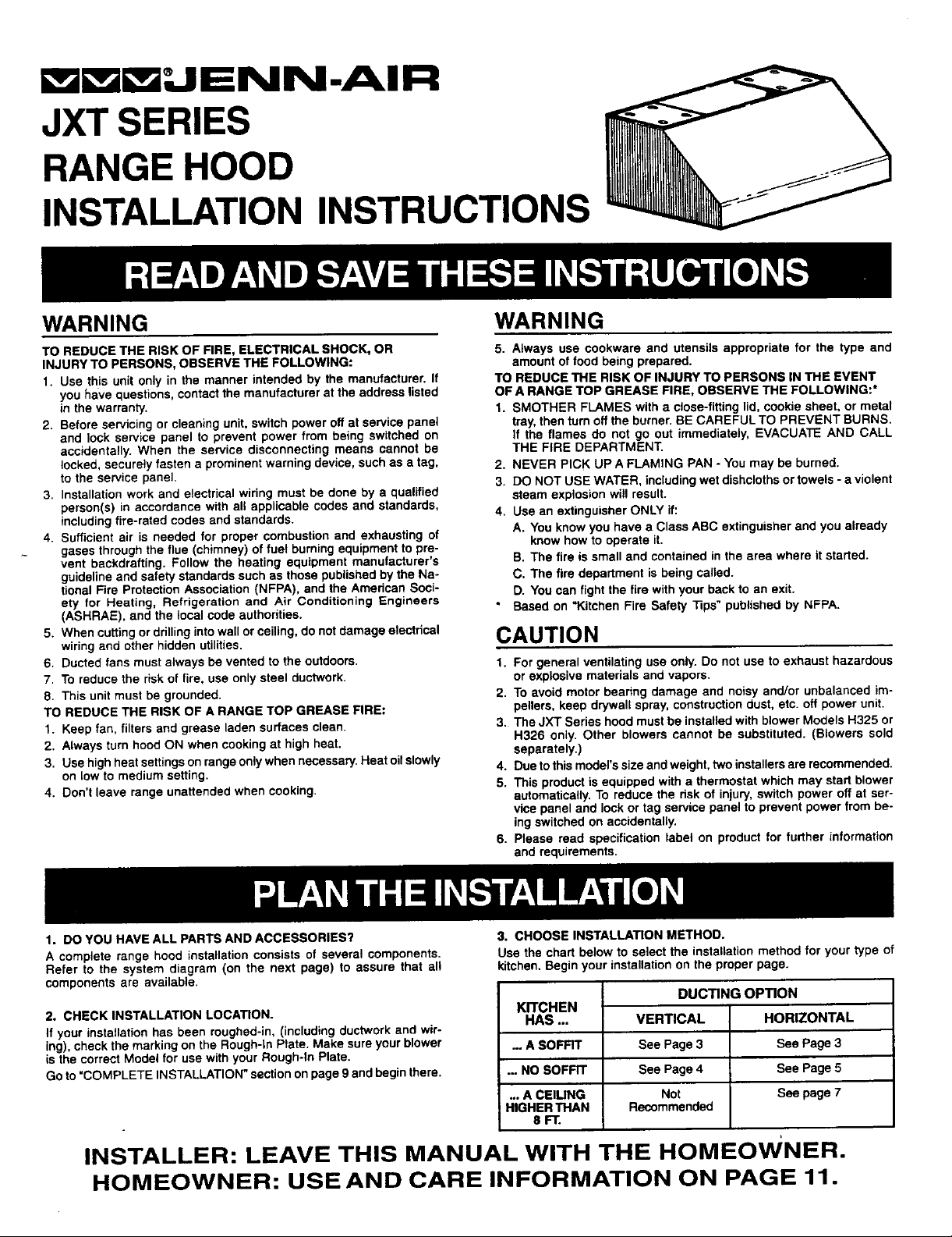
JXT SERIES
RANGE HOOD
INSTALLATION INSTRUCTIONS
EAD ANDSAVETHESEINSTRUCTIONS
WARNING WARNING
TO REDUCETHE RISK OF FIRE, ELECTRICALSHOCK,OR 5. Alwaysuse cookwareand utensilsappropriatefor the type and
INJURYTO PERSONS,OBSERVETHE FOLLOWING: amountof foodbeingprepared.
1. Use thisunit onlyin the mannerintendedby the manufacturer.If TO REDUCETHE RISKOF INJURYTO PERSONSIN THE EVENT
you havequestions,contactthemanufacturerat the addresslisted OF A RANGETOP GREASE FIRE,OBSERVETHE FOLLOWING:*
inthe warranty. 1. SMOTHER FLAMESwitha close-fittinglid,cookiesheet,or metal
2. Beforeservicingor cleaningunit,switchpoweroffat servicepanel tray,thenturnofftheburner.BE CAREFULTO PREVENT BURNS.
and lock service panel to preventpower from being switchedon If the flames do not go out immediately,EVACUATEAND CALL
accidentally.When the service disconnectingmeans cannot be THE FIRE DEPARTMENT.
locked,securelyfastena prominentwarningdevice,suchas a tag, 2. NEVER PICK UPA FLAMINGPAN - Youmaybe burned.
to the service panel. 3. DO NOTUSEWATER,includingwetdishclothsortowels-a violent
3. Installationworkand electricalwiringmustbedone by a qualified steamexplosionwillresult.
person(s)in accordancewith all applicablecodesand standards, 4. UseanextinguisherONLYif:
includingfire-ratedcodesandstandards.
4. Sufficientair is needed for propercombustionand exhaustingof knowhowtooperateit.
gasesthroughtheflue (chimney)of fuel burningequipmentto pre-
vent beckdrafting.Followthe heating equipmentmanufacturer's B. The fire is smalland containedinthe area whereit started.
guidelineand safetystandardssuchas thosepublishedby theNa- C. The fire departmentisbeingcalled.
tionalFire ProtectionAssociation(NFPA),and theAmericanSoci- D. Youcanfightthe firewithyourbackto an exit.
ely for Heating, Refrigerationand Air Conditioning Engineers " Basedon"KitchenFire Safety "Nps"publishedbyNFPA.
(ASHRAE),andthe localcodeauthorities.
5. Whencuttingordrillingintowallorceiling,donot damageelectrical CAUTION
wiringand otherhiddenutilities.
6. Ductedfansmustalwaysbeventedto the outdoors. 1. Forgeneralventilatinguseonly.Do not useto exhaust hazardous
7. Toreduce the riskof fire, use onlysteel ductwork, orexplosivematerialsandvapors.
8. Thisunitmustbe grounded. 2. Toavoid motorbearingdamageand noisyand/orunbalancedim-
TO REDUCETHE RISK OFA RANGETOP GREASEFIRE; pollers,keep drywallspray,constructiondust,etc. offpowerunit.
1. Keepfan,filtersand greaseladen surfacesclean. 3. TheJXTSerieshoodmustbe installedwithblowerModelsH325or
2. AlwaysturnhoodONwhencookingat highheat. separately.)
3. Usehighheatsettingsonrangeonlywhennecessary.Heatoilslowly 4. Duetothismodel'ssizeandweight,twoinstallersarerecommended.
onlowto mediumsetting. 5. Thisproductisequippedwitha thermostatwhichmay startblower
4. Don'tleave rangeunattendedwhen cooking, automatically.To reducethe riskof injury,switchpoweroffat ser-
A. Youknowyou havea ClassABC extinguisherandyou already
H326 only. Other blowerscannot be substituted.(Blowers sold
vicepanel and lockor tagservicepanelto preventpower frombe-
ingswitchedon accidentally.
6. Please read specificationlabel on productfor furtherinformation
and requirements.
PLANTHEIN,c;TALLATION
1. DOYOU HAVEALL PARTSAND ACCESSORIES? 3. CHOOSEINSTALLATIONMETHOD.
A completerange hood installationconsistsof several components. Usethe chartbelow toselect the installationmethodforyourtype of
Refer to the systemdiagram (on the next page) to assure that all kitchen.Beginyourinstallationonthe properpage.
componentsare available.
2. CHECKINSTALLATIONLOCATION. KITCHEN
If yourinstallationhasbeen roughed-in,(includingductworkandwir-
ing),checkthemarkingon theRough-InPlate.Makesureyourblower ...A SOFFIT See Page3 See Page3
isthecorrectModelfor usewithyourRough*InPlate.
Goto"COMPLETEINSTALLATION"sectiononpage9andbeginthere.... NOSOFFIT See Page4 SeePage5
HAS ... VERTICAL HORIZONTAL
... A CEIUNG Not Seepage7
HIGHERTHAN Recommended
8FT.
INSTALLER: LEAVE THIS MANUAL WITH THE HOMEOWNER.
HOMEOWNER: USE AND CARE INFORMATION ON PAGE 11.
DUCTING OPTION
J
Page 2
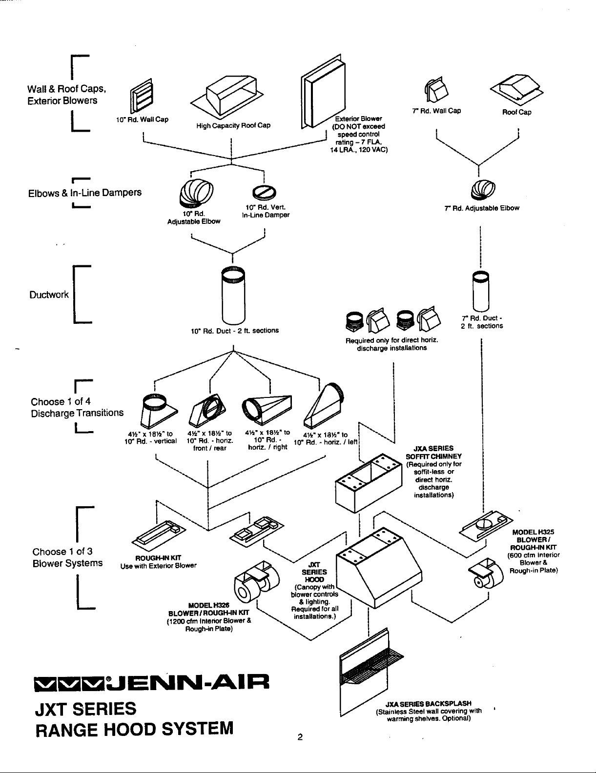
WExtl/r&°rRB/°°fwCsPS'L
10"Rd.Wall Cap " Blower 7" Rd.WallCap RoofCap
,Oow ,,n-Un Oa oers
Discharge Transitions
Choose 1 of_4 __ dischargeinstallations
I_ 10" Rd. Vert.
L_ _
4½"x 18_" tO 4_'x tS_" to 4½"xlSYz"to 4½"x 18½"to
10" Rd. - vsrticol 10"Rd, - horiz. 10"Rd. - 10"Rd.- horiz./ leffl _,
!. _ SOFFITCHIMNEY
t0" Rd. In-LineDamper 7" Rd. AdjustableElbow
AdjustableElbow
10" R(_.Duct- 2 ft. sections 2 ft. sections
Requiredonlyfordirecthodz,
front/rear hortz./ hght JXASERIES
.,_ (Requiredonlyfor
soffit-less or
directhoriz.
discharge
installations)
I
F MODELH325
Choose 1of3 ROUGH-INKIT
BlowerSystems ROUGH-INKIT (600 cfm Interior
L SERIES Rough-inPlate)
UsewithExteriorBlower JXT _ Blower&
HOOD
(Canopywith
MODELH326 & lighting.
BLOWER/ROUGH-IN KIT Requiredforall
(1200 cfmInteriorBlower& installations.)
Rough-inPlate)
blowercon,_,, _
BLOWER/
i_i_UENN-AIR
JXT SERIES _,,SE._SB,c.,,,=
RANGEHOODSYSTEM warmingshelves.Optional)
2
(StainlessSteelwallcoveringwith
Page 3
VERTI(;AL/ HORIZ()NTALDUCTING(W_THSOFRT)
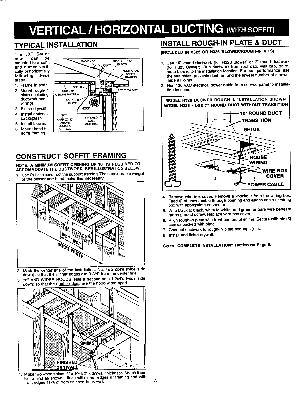
TYPICAL INSTALLATION INSTALL ROUGH-IN PLATE & DUCT
The JXT Series (INCLUDED IN H325 OR H326 BLOWER/ROUGH-IN KITS)
hood can be
mountedto a soffit = R_'_ _FC,APROOFCAP TRANSR3ON OR
andductedverti-__,,_ _c, ELBOW 1. Use 10" roundductwork(for H326 Blower)or 7" roundductwork• (for H325 Blower).Run ductworkfrom roof cap, wall cap, or re-
callyorhorizontally _,__ / AOOmONAL moteblowertothe installationlocation.Forbestperformance,use
steps: _ MING thestraightestpossibleductrunandthefewestnumberof elbows.
1. Framein soffit "-'-"_ 2. Run120VACelectricalpowercablefrom servicepanelto installa-
2. Mountrough-in FINISHED / /_1111" _ WALLCAP tion location.
plate(including CElUNGMATERIAL
wiring) pLATE
3. Finishdrywall MODEL H325 - USE 7" ROUND DUCT WITHOUT TRANSITION_
ductworkand CEI__ 1
4. Installoptional FIN,SHED / I _ 10" ROUND DUCT J
backsplash APPROX._0' W_-L TRANSITION
_,nsta,,0,ower_O_,NOABOVEMATER,AL --_.j:--_.--" /
6. Mounthoodto SURFACE
SOffitfram)ng _;._/'_\ SHIMS J
ACCOMMODATETHEDUCTWORK. SEEILLUSTRATIONBELOW.
NOTE"AM,NIUBOFF,TOPEN,NGO_,0",_REOU,REDTO IN _ _N_ /
1. Use2x4'stoconstructthesupportframing.Theconsiderableweight _ _ _ WIRE BOX |
of the blower and hoodmake this necessary. I _ I _ COVER |
ROUGH-IN MODEL H326 BLOWER ROUGH'IN INSTALLATION SHOWN
Tapeall joinLs.
2. Mark the centerline of the installation.Nailtwo 2x4's (wide side
down)sothat theirinneredcas are 9-3/4"fromthecenter tina.
3. 36"AND WIDER HOODS: Nail a secondset of 2x4's(wide side
down)sothattheirouter edoesare the hood-widthapart.
4. Removewireboxcover. Removea knockoutfromthe wiringbox.
Feed6" of powercablethroughopeningand attachcableto wiring
boxwithappropriateconnector.
5. Wire blacktoblack,whitetowhite,andgreenor barewirebeneath
greengroundscrew.Replacewireboxcover.
6. Alignrough-inplatewithfrontcornersofshims.Securewith six(6)
screwspackedwithplate.
7. Connectductworkto rough-inplate and tapejoint.
8. Installand finishdrp_vall.
Go to "COMPLETEINSTALLATION" section on Page g.
4. Maketwowoodshims:2" x 10-1/2"x drywallthickness.Attachthem
to framingas shown- flushwith inneredges of framingand with
frontedges11-1/2" fromfinishedbackwall. 3
Page 4
VERTICALDUCTINGNOSOFFIT
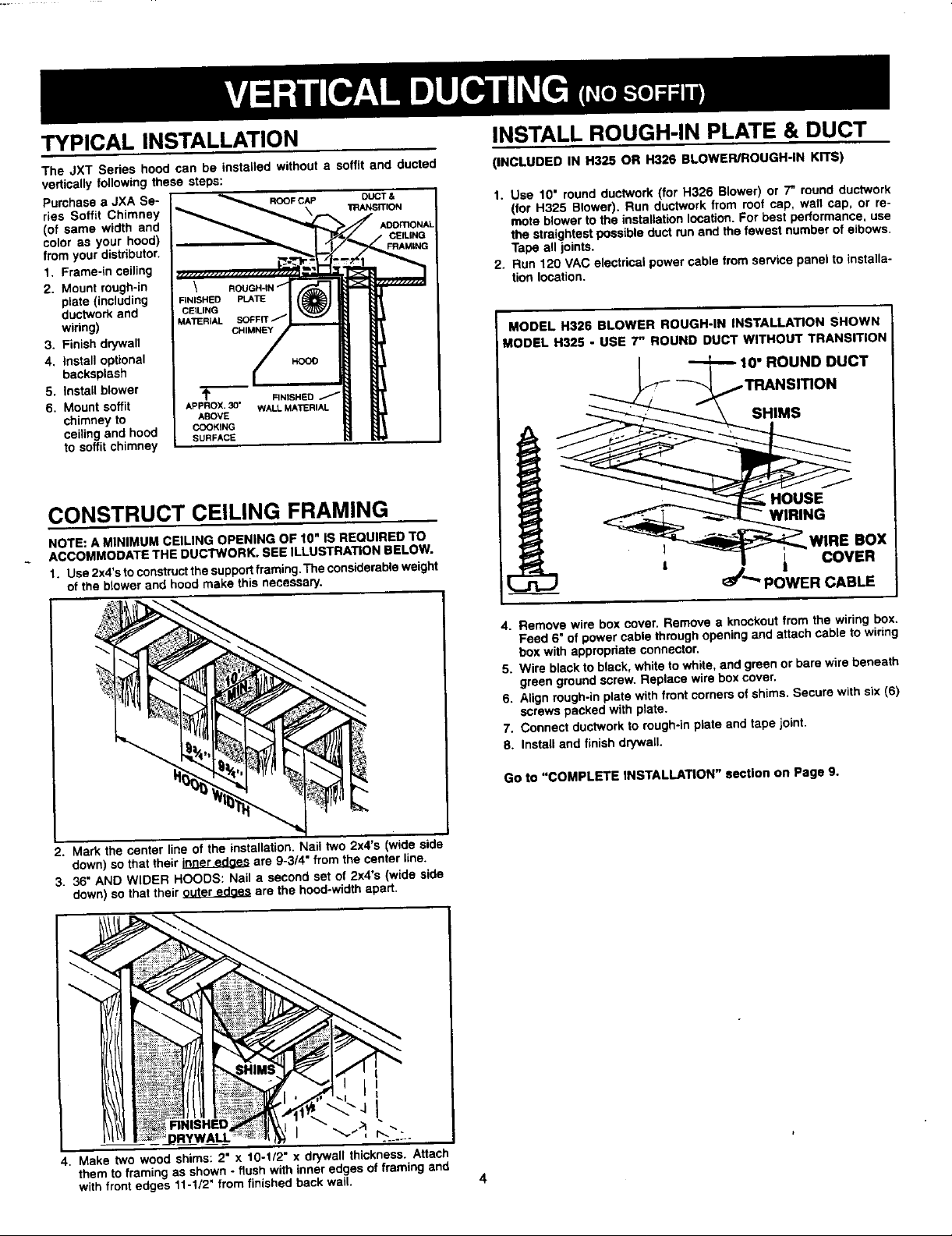
TYPICAL INSTALLATION INSTALLROUGH-INPLATE& DUCT
The JXT Series hood can be installed withouta soffit and ducted (INCLUDED IN H325 OR H326 BLOWER/ROUGH-IN KITS)
verticallyfollowingthese steps:
ries Soffit Chimney (for H325 Blower). Run ductworkfrom roof cap, wall cap, or re-
coloras your hood) OElUNO the straightestpossibleductrunand the fewestnumberof elbows.
fromyourdistributor. /_'_M=NU Tapeall joints.
(ofPUrchaSesamea JXAandSe"I _ TRANSrTIONROOFCAP _,._,_/_._==,.u_DUOT&'='DDmON_1. Use 10" roundductwork(for H326 Blower)or 7" roundductwork
1. Frame-inceiling I _'-'_'_J",=_ _ 2. Run 120VACelectricalpowercable fromservicepanelto installa-
2. Mountrough-in \ ROUGH-IN
3. Finishdrywall MODEL H325 - USE 7" ROUND DUCT WITHOUT TRANSITION/
4, Install optional Hood
5. Installblower _ F,NISHED_ ......_-- _TRANSITION /
6, Mountsoffit APPROX. 30" WALL MATERIAL
width // moteblowertothe best performance,use
tion location.
ductworkand CEfLING
wiring) MATERIAL SOFFIT ]
backsplesh 10" ROUND DUCT
CHIMNEY/ MODEL H326 BLOWER ROUGH'IN INSTALLATION SHOWN
Forinstallationlocation.
oh,mneytoABOVE
plate(including FINISHED_-"_ fl_)/ 1 _ _-- __"( _ SHIMS ///
to soffitchimney SURFACE _ ,,
CONSTRUCTCEILINGFRAMING
NOTE:AM,N,MOMCE,.NGOPENINGOF,0",SREOU,REOTO I N /
_ ACCOMMODATETHEDUCTWORK.SEEILLUSTRATIONBELOW. I _, _I_._WIRE BOX /
1. Use2x4'stoconstructthesupportframing,Theconsiderableweight I _J ' } I COVER |
ofthe blowerend hoodmakethis necessary, 1_ _/_'_ POWER CABLE ]
4. Removewire boxcover, Removea knockoutfromthewiringbox.
Feed 6" of powercable throughopeningandattachcable to wiring
boxwithappropriateconnector,
5. Wire blacktoblack,whiteto white,andgreen orbarewirebeneath
greengroundscrew.Replacewireboxcover,
6. Alignrough-inplatewithfrontcornersofshims,Securewithsix(6)
screwspackedwith plate.
7. Connectductworkto rough-inplateand tapejoint.
8. Installandfinishdq/wall.
2. Markthe centerlineof the installation.Nail two2x4's (wideside
down)so thattheirinneredges are 9-3/4"fromthe centerline.
3. 36" AND WIDER HOODS: Nail a secondset of 2x4's(wide side
down)so thattheirouter educeare thehood-widthapart.
I
RNISHED
DRYWALL I "_, _.._.:._
4. Make two woodshims:2" x 10-1/2"x dq/wallthickness.Attach
themtoframingas shown- flushwithinneredgesof framingand
withfrontedges 11-1/2"fromfinishedbackwall. 4
Go to "COMPLETE INSTALLATION" section on Page 9.
Page 5

H()RIZONTAI_DUCTING NoSOFFIT
TYPICAL INSTALLATION = .... ....
The JXT Series hood can be installedwithout a soffitand ducted FINISHEDCEILING :
horizontallythroughan outsidewall. Followthesesteps:
Purchasea JXASeries SoffitChimney(of same widthand coloras
your hood)fromyourdistributor.
1. andFrame'inwallceiling __ _ =..... _ _ . I , --
2. Mountrough-in !
plateto wall _"- _ _ " "
,,nouding x INBHED
ductworkand F,_s,_ I CEILINGTHICKNESS
wiring) ,A_,,_. C.,_ _r
4. Installoptional Pt.A_ =DucT.
becksplash i
5. Secureblowerto ,r_ FLUSH--,_
3. Finishdrywall ____F_?.._._w,,_u..*TEnU__ wp._C*p Ii =_ m==
rough-inplate A_v_ w,,_u._'rER_ I
6. Mountsoffit cooKr_
chimneyto sC_°_c_ " _ 2. Make twowoodshims-2"xlOY2"xfinished wallthickness.Attach
ceilingand hood OUT 2 x 4's).
tosoffitchimney
CEtLtNG SOPRT_ _ HORZZO_'TAL
H
themto framingas shown(flushwithinsideedgesof WIDE SIDE
3. Cut hole(s)in wallsheathing.Referto properillustrationforblower
modelyouare using.
• TOP PLATE
CONSTRUCTCEILING FRAMING MODELH326DUAL-WHEELBLOWER
1. Use2x4's to constructthe ca{lingframing. LINEON SHEATHING TOPPLATE
~ 5/8"BELOWFINISHEDCEILING :
!i -_ ,_-
: : • WOO.D.SHIMS
CEILING THICKNESS
2 xl0½ xFINISHED
2. Mark the centerline of the installation.Nail two 2x4's (wideside
down)sothat theirinneredaesare 9-3/4"fromthe centerline. : LINEON SHEATHING
3. 36" AND WIDER HOODS: Nail a secondset of 2x4's (wide side =:5/8"BELOW FINISHEDCEILING ,,
down)sothat theirouter edaesare the hood-widthapart, tL
CONSTRUCTWALLFRAMING L.
.o._ooEo_o.G..,._,E I----,I_---_"I--
CENTEREO OVER RANGE AFIF.,A : ; ?; WOOD SHIMS
,_ : : _ I _LEFTEDGE
, _ '_ OFSHIM CEILINGTHICKNESS
I 2x4's WALLSTUDS"_, .
I WIDESIOEOUT • )
1. Use 2x4'sto constructwallframingas shown.
5
MODEL H325 SINGLE-WHEEL BLOWER
TOPPLATE
_l m _ _ _ m
_Y
I : |
2" x 10½" xFINISHED
/
/
I
Page 6

INSTALL ROUGH-IN PLATE & DUCT
1. Run 120VAC electricalpowercable fromservicepanelto installa-
tionlocation.
2. Removewire boxcover.Removea knockoutfrom thewiringbox. MODEL H32B BLOWER ONLY
Feed6" of powercablethroughopeningandattachcableto wiring 5. Purchasea Model457K HorizontalDuctingKit.
boxwithappropriateconnector. Connectrectangular-to-roundtransitionsto backsideof rough-in
3. Wireblackto black,whitetowhite, andgreenor barewire beneath plate.Mountwallcapsto outsidewall.Tapealljoints.
greengroundscrew.Replacewireboxcover,
ALL BLOWERS- (H326 ROUGH-IN PLATE SHOWN) I MODEL H325 BLOWER ONLY
!iii_i ii/fill/
4. Mountrough-inplatetoframing.Make suretop andouteredgesof
rough-inplateare FLUSH withtopand outeredgesof shims.
5. Install a wall capthataccepts7" roundduct.Use a shortsection
ofductbetweenrough-inplateandwallcapif necessary.Tapeall
joints.
1
6. Installand finishdrywall.
Go to "COMPLETE INSTALLATION" sectionon Page 9.
Page 7

H( )RIZONTAL DUCTING (CEILINGS HIGHER THAN BFT.)
TYPICAL INSTALLATION 3. Cut hole(s)in wallsheathing.Referto properillustrationfor blower
The JXT Serieshoodcan be ductedhorizontallythroughan outside
wall, wheretheceilingishigherthan8 ft. Followthesesteps: MODEL H326 DUAL-WHEEL BLOWER
Purchasea JXA SeriesSoffit Chimney(of same widthand color as
your hood) from LINEON SHEATHING ToP PLATE
your distributor. _" ADOITX:_W. 5/8" BELOWFINISHEDCEILING
1. Frame-inwaft WAU.FmLMINO ....... _ I/'_
2. Mountrough-in
ductworkandPlate(including _/_'tl "_',_
wiring) • l"- _ _
3. Finishdrywall I oR
4. Installoptional PL_T I
baoks0lash Z
5. Secureblowerto J s
roogh-inplate "+'------ _ r""-.H_._.,._l " _ _,.s._,,_ "--._ /
6. Mountsoffit ABOVE WALLMATERIAL _ I/
chimneyto wall COOKING
and hood to SURFACE ! WOODSHIMS
soffitchimney L LEFT EDGE i 2" x 10½"x FINISHED
CONSTRUCT WALL FRAMING LINEON SHEATHNG TOP PLATE
APPROX, 30" FINISHED / _ m Bl_
SOFRT _
CH,M.EY __j= "_lflll DUCTINQKIT
ROUGH-IN WALLCAP
_._ _1: _ HORIZONTAL -- --
/ / ....
....... / . _ _ _
, - I-4---.---......
modelyouare using.
\
OF SHIM i............................ ' CEILINGTHICKNESS
MODEL H325 SINGLE-WHEEL BLOWER
; ,5/8"BELOWFI_NISHEDCEILING /
: I 2,4,, I I 'VVALLSTLID$I I ' ,--I _ _.,....j/_ "
1. Use2x4's to constructwallframingas shown. OFSHIM CEILINGTHICKNESS
LINEON sHEATHING
5/8"BELOWFINISHEDCEILING /
- ! HOOD W1DTH I | .|
L - |
W,DESIDEOUTI I I I ' J
I add second set of 2 X 4'sfor I I :
,oo=._r,_.._. , I I
14-.. LEFT 2" x 10½"x FINISHED
EDGE
WOOD SHIMS
/
\
2"x 10½"x FINISHED -
CEILINGTHICKNESS
-,I--FLUSH :FLU;H
2. Maketwowoodshims- 2" x 10½" x finished wall thickness.Attach
them to framing as shown(flushwithinside edgesof WIDE SIDE
OUT 2 x 4's),
=
Page 8

INSTALL ROUGH-IN PLATE & DUCT
1. tionRUnlocation.120VACelectricalpowercablefrom servicepanelto installa- MODEL H326 BLOWER ONLY I
2. Removewire boxcover.Removea knockoutfromthe widngbox. 5. Usinga hodzontalductingkit,connectrectangular-to-roundtran-
Feed6" of powercablethroughopeningandattachcabletowiring sitionstoback sideof rough-inplate. Mountwall capstooutsde J
boxwithappropriateconnector, wall.Tape alljoints.
3. Wireblackto black,whitetowhite,andgreenor barewirebeneath
greengroundscrew.Replacewireboxcover.
ALL BLOWERS- (H326 ROUGH-IN PLATE SHOWN) 5. Installa wallcapthataccepts7"roundduct.Usea shortsection
ofductbetweenrough-inplateandwallcap ifnecessary.Tapeall
joints.
6. Installandfinishdrywall.
Go to "COMPLETE INSTALLATION" section on Page 9,
,J
4. Mountrough-inplateto framing.Makesuretopand outeredgesof
rough-inplateare FLUSHwithtopand outeredgesof shims.
MODEL H325 BLOWER ONLY
I
Page 9

COMPLETEINSTALLATI()N
LOCATE HOODMOUNTINGSCREWS MOUNTBLOWER
INCLUDED IN H325 OR H326 BLOWER/ROUGH-IN KITS)
ROUGH-IN_L H326
PLATE _ DUAL WHEEL
BARREL NUT.,__ /
1. Loosenbarrelnuthalf-way.
2. Liftblowertorough-inplate.Slideblowerback(downforhori-
zontalinstallation)toengageblowertabwith slotin plateand
1. Markthe locationof four(4) innermountingscrewsonthe soffitor blowerslotwithbarrelnut.
ceilingfollowingdimensionsshown.Drivethescrewshalf-wayinto 3. ]]ghten barrelnutto secureblowerto rough-inplate.
INSTALLBACKSPL.___ASH(OPTIONAL)
the framing. STU_
- NOTE ROUGH-IN" _ / _ MODEL H325
I BACKSPLASH MUST BE INSTALLED BEFORE HOOD SHELL PLATE -_\_;;_ SINGLE WHEEL
I BECAUSE HOOD SHELL COVERS BACKSPLASH'S TOP . "_'M'- _T_-,.._ BLOWER
MOUNTING SCREWS. SEE INSTRUCTIONS PACKED WITH 1. Loosenbarrelnuts I'_'V_'_,'_,4_\ _/ -
I BACKSPLASH.
andwingnuthalf- ; _'_ _)1_'_ _
2. Uft blowerto rough- _____,,_ / l
inplate andover _l_1_ _ BARREL
barrelnuts.Slide 1 "_.___ NUT
blowersidewardto _
way. _'-_"_/ '_\'_ " ) U
engagebarrelnuts h_ _---
withsmallend of keyholesand wingnutwithslot.
3. "Nghtennutstosecureblowerto rough-inplate.
INSTALLSOPHTCHIMNEY(optional)USINGINSTRUCTIONSPACKEDWITHIT.
INSTALL HOOD
I INNER MOUNTING
1. Lifthoodintopositionandhang itfromthe four(4) innermountin,
screws.Make surescrewsare engagedin smal!end of keyholes
and hoodis againstthewall -then tightenscrewssecurely.
2. Drivefour(4) additionalmountingscrewsthroughthe smallendof
outerkeyholes,throughthe drywall,andintothe framing.
9
Page 10

INSTALL HOOD (CONTINUED)
BECAUSE OFTHE WEIGHT OF THE HOOD - MAKESURETHAT
THEOUTER MOUNTINGSCREWS ARE DRIVENINTOTHE SOF-
FIT FRAMNG AND NOT JUST THE DRYWALl
NOTE
ROUGH-INPLATE
POWERCORD
• I
-- BLOWERPOWERCORD
3, Plugthe rough-inplatepowercordand theblowerpowercordinto
thelightpanelas shown.
LEDGE _ J
4. Setaluminumfiltersinplaceonthefrontandrearledges,asshown.
5. Installtwo(2) heat lampbulbs.Usa BR40 size,250W Max., Infra-
red bulbsonly.(Purchaseseparately)
6. Installthree(3)halogenlightbulbs.Use PAR20,50Wattsize. (Pur-
chaseseparately)
7. Turnonpowerand checkoperation.
10
Page 11

USE AND CARE
CONTROLS FILTERS
Alwaysturn your hood on beforeyoubegincockingto establishan air Clean filtersfrequentlyin a detergentsolution°Theyare dishwasher
flowinthe kitchen.Lettheblowerrunfor a few minutesto clearthe air safe.
afteryouturntherangeoff.Thiswillhelpkeepthewholekitchencleaner Replacementfiltersare availablefrom your dealer. See label inside
and brighter, hoodfor sizeand partnumber.
WARMINGLAMP BLOWER CLEANING
SWITCHES ON/ OFF SWITCH
UNPLUG POWER CORDS FROM CONTROL PANEL BEFORE
CLEANING OR SERVICINGHOOD.
i CAUTION 1
HOODCLEANING
Stainlesssteel is one of the easiestmaterialsto keep clean. Occa-
sionalcarewillhelppreserveitsfine appearance,
Cleaningtips:
• Hotwaterwithsoap or detergentisallthatis usuallyneeded.
• Followallcleaningby rinsingwithclearwater.Wipe dry witha
clean, softcloth to avoidwater marks.
• Fordiscolorationsordepositsthatpersist,usea non-scratching
householdcleanseror stainlesssteel polishingpowderwith a
littlewaterand a softcloth.
• For stubborncases,use a plasticscouringpad or soft bristle
brushtogetherwith cleaserandwater. Rublightlyindirectionof
polishinglinesor *grain"of thestainlessfinish.Avoidusingtoo
SLOWER much pressure which maymar the surface.
SPEED * DO NOT useordinarysteelwoolor steel brushes,Small bitsof
HALOGEN CONTROL steel may adhere to the surfacecausingrust.
WARMING LIGHT • DO NOT allow saltsolutions,disinfectants,bleaches,or clean-
LAMPS SWITCHES ing compoundstoremainin contactwithstainlesssteelfor ex-
(frontswitch- centerlight) tendedperiods.Many of these compoundscontainchemicals
(rearswitch- sidelights) Whichmaybe harmful.Rinsewithwaterafterexposureandwipe
* DONOT allowdepositstoremainfor longperiodsoftime.
drywitha cleancloth.
BLOWER SLOWER CLEANING
The blowerisoperatedusingtwo(2) controls,
Use the red, lightedon/offswitchto start and stop the blower.When
turnedon, the blowerwilloperateat the previoussettingofthe speed
control. HOWTO AVOIDA COMMON RANGE-TOPGREASE FIRE:
Turn the speed controlknob clockwiseto decrease blowerspeed - * Yourhoodprovidesa protectivebarrierbetwae the cooking
counterclockwiseto increase speed, surfaceandthe cabinets.
COOKTOP LIGHTING (HALOGEN) " Always turn hoodON when cookingat high heatto keepthe
A doubleset of on/offswitchescontrolthe halogenlights, cookingareaandthe hoodcooler.
The frontrockercontrolsthecenterlight.Therear rockercontrolsboth * Use highheat settingsonlywhen necessary.
side lights.Selectone, two,or threelightsforbestcooktoplighting. * Neverleave cookingsurface unattended.Boil-overcauses
UsePAR 20, 50 Watt halogenbulbs.(Purchaseseparately) * If preparingflamingfoods,such asCherriesJubilee,always
WARMINGLAMPS(INFRARED) cancause damageor fire.
Each warminglampis controlledwith itsownon/offswitch. FIRE:
UseonlyBR40Size,250W Max. Infraredbulbs.(Purchaseseparately) * Never pickupa flamingpan. If dropped,flamescan spread
CAUTION: DO NOT PLACE HIGHLY FLAMMABLE MATERIAL ON quickly.
WARMING SHELVES. ° DO NOT USE WATER!Aviolentsteamexp(osionmayresult.
HEAT SENTRYTM tray
Yourhoodis equippedwitha Heat SentryTM thermostat.Thisthermo- a multi-purposedry chemicalextinguisher.
staris a device that will turn on or speed up the blowerif it senses * Turnoffsurfaceunits-ifyou can dosowithoutgettingburned.
excessiveheatabovethe cookingsurface.
1) If blowerisOFF - it turnsblowerON to HtGHspeed.
2) If blowerisONat a lowerspeedsetting- itturnsbloweruptoHIGH
speed.
When thetemperaturelevel dropsto normal,theblowerwillreturnto
its originalsetting. 11
Vacuumblower toclean.Donot immersein water,
* Keepfan, filtersand greaseladensurfacesCLEANaccord-
ing to instructions.
smokingandgreasyspilloversthatmayignite,
turnhoodON to HIGHto preventa highheat situationwhich
HOW TO EXTINGUISH A COMMON RANGE-TOP GREASE
Wet dishclothsortowels arealsodangerous.
• Smotherflameswitha close-fittinglid,cookiesheetor metal
* Flaminggreasecan alsobe extinguishedwithbakingsoda or
Page 12

JENN-AIRWARRANTY
Congratulationsonyourpurchaseofa Jenn-Airappliance.Wewishtoexpressourconfidenceintheproductbyadvisingyouofourwarranty.
AllJenn-Airappliancescarrya minimumwarrantyof 1styear fullwarrantypartsand labor,plusa 2nd year limitedwarrantypartsonly.
Warrantiesbeginonthedateof purchase.Thechartbelowdetailsspecificwarrantiesbyproductcategory.Theyearsafterdateof original
purchaseare listedacrossthe top.
YEARS
PRODUCT 1 2 3 4 5
Cooktop,Range, Parts All All Glass CeramicTop due to thermalbreakage.
WallOven Radiant,Halogenand SolidElementFailure.
(Gas or Electric) Electronic
Labor Yes ControlPanel
Components
Accessories Radiant, Halogenand Solid ElementFailure.
Combination Parts All All Microprocessor,Power& MicroprocessorTransformer,
MicrowaveWall/Oven Capacitor,Rectifier,TdacAssembly
or MicrowaveOven Electronic Limitedto Magnetron,TouchPadAssembly,
- Components Capacitor,Rectifier,TriacAssembly
Parts All All GlassCeramicTopdue to thermalbreakage.
Labor Yes
LimitedtoMagnetron,TouchPadAssembly,
Labor Yes ControlPanel Microprocessor,Power& MicroprocessorTransformer,
OWNERS'RESPONSIBILmES
The customerhascertain responsibilitieswhichmustbesatisfiedto qualifyfor coverageunderthesewarranties.
Forall products,the ownerisresponsibleforprovidingnormalcareand maintenancein accordancewiththe Use & Care instructions,
providingproofof purchaseon request,properinstallationandmakingtheappliancereasonablyaccessibleforservice.Warrantiesare
forfailurein normalhomeuse.
WARRANTYSERVICE
Underthefullwarranty,servicemustbe performedbyan AuthodzedJenn-AirServiceContractor.To obtainservice,contactthe dealer
fromwhomthe unitwaspurchased,an authorizedservicecontractor,or contactJenn-AirCustomerAssistance,cJoMaytagCustomer
Service,P.O. Box2370, Cleveland,TN 37320-2370,1-800-688-1100.Pleaseincludemodelnumber,serialnumber,anddate of original
retailpurchaseinallcorrespondence.Servicewillbe providedduringnormalbusinesshours.Allreplacementpartsassumetheunused
portionof thiswarranty.
Limitedpartswarrantycoverscostof partsonly.Tripcharge,transportationandlaborcostsarethe responsibilityoftheowner.
Thiswarrantygivesyouspecificlegalrights,andyoumayalsohave otherdghtswhichvaryfromstateto state. I
CANADIAN RESIDENTS
Thiswarrantycoversonlythoseappliancesinstalledin Canadathathave beenlistedwithCanadianStandardsAssociationof Canadian
Gas Associationunlessthe appliancesare broughtintoCanadadueto transferof residencefrom theUnitedStatesto Canada.
FOR YOUR RECORDS
Recordthefollowinginformationandretainthisentiresheetforyourfuturereference.
ModelNumber Sedal Number Date Purchased
II;JENN-AIR
JENN-AIR COMPANY
ONE DI=PENDABILTY SQ.
NEVMTON, IOWA 50208_)039 99042594A
 Loading...