

Jenn-Air JXT5836ADS, JXT5830ADW, JXT5830ADS, JXT5836ADB, JXT6030ADS Service
...
Service
This manual is to be used by qualified appliance
technicians only. Maytag does not assume any
responsibility for property damage or personal
injury for improper service procedures done by
an unqualified person.
This Base Manual covers general information
Refer to individual Technical Sheet
for information on specific models
This manual includes, but is
not limited to the following:
Vent Hoods
JXT5830ADB/W/S
JXT5836ADB/W/S
JXT6030ADS
JXT6036ADS
JXT8030ADS
JXT8036ADS
JXT8042ADS
JXT8136ADS
JXT8142ADS
JXT9030CDP
JXT9036CDP
JXT9048CDP
JXT9130CDP
JXT9136CDP
16023510
November 2004
©2004 Maytag Services
Important Information
Pride and workmanship go into every product to provide our customers with quality products. It is possible, however,
that during its lifetime a product may require service. Products should be serviced only by a qualified service
technician who is familiar with the safety procedures required in the repair and who is equipped with the proper tools,
parts, testing instruments and the appropriate service information. IT IS THE TECHNICIANS RESPONSIBILITY TO
REVIEW ALL APPROPRIATE SERVICE INFORMATION BEFORE BEGINNING REPAIRS.
Important Notices for Servicers and Consumers
!
To avoid risk of severe personal injury or death, disconnect power before working/servicing on appliance to avoid
electrical shock.
To locate an authorized servicer, please consult your telephone book or the dealer from whom you purchased this
product. For further assistance, please contact:
WARNING
Customer Service Support Center
CAIR Center
Web Site Telephone Number
WWW.JENNAIR.COM ............................................. 1-800-688-1100
CAIR Center in Canada ........................................... 1-800-688-2002
Recognize Safety Symbols, Words, and Labels
DANGER!
DANGER—Immediate hazards which WILL result in severe personal injury or death.
WARNING!
WARNING—Hazards or unsafe practices which COULD result in severe personal injury or death.
CAUTION!
CAUTION—Hazards or unsafe practices which COULD result in minor personal injury, product or property
damage.
2 16023510 ©2004 Maytag Services

Table of Contents
Important Information .................................................... 2
Important Safety Information
In Case of Fire.......................................................... 4
Safety Practices for Servicer .................................... 4
Servicing .................................................................. 4
Electrical Requirements ........................................... 5
Extension Cord ........................................................ 5
Receiving Vent Hood ................................................ 5
Precautions .............................................................. 5
Using the Vent Hood ................................................ 5
General Information
Cooking Nomenclature ............................................. 6
Specifications .......................................................... 7
Placement of the Vent Hood .................................... 7
Do Not Block Air Vents ............................................ 7
Location of Model Number ........................................ 7
Grounding Instructions ............................................. 7
Model Identification .................................................. 7
Service ..................................................................... 7
Parts and Accessories ............................................. 7
Extended Service Plan ............................................. 7
Vent Hood Description ............................................. 8
Troubleshooting Procedures ......................................... 9
Testing Procedures ......................................................11
Disassembly Procedures for Models JXT9030CDP,
JXT9036CDP, JXT9048CDP, JXT9130CDP, JXT9136CDP
Halogen Light Removal ............................................ 13
Heat Lamp Removal ................................................ 13
Grease Filter/Grease Filtger Cover Removal............ 13
Halogen Light Socket .............................................. 13
Heat Lamp Socket Removal .................................... 13
Light Panel Removal ...............................................14
Control Board Removal ............................................ 14
Touch Pad Removal ................................................ 14
Capacitor Removal .................................................. 14
Transformer Removal ............................................... 15
Blower Motor Removal ............................................ 15
Filter Spring Clip Removal ....................................... 15
Disassembly Procedures for Models JXT8042ADS,
JXT8142ADS, JXT58309AD*, JXT5836AD*
Halogen Light Removal ............................................ 16
Grease Filter/Grease Filtger Cover Removal............ 16
Halogen Light Socket .............................................. 16
Control Board Removal ............................................ 16
Control Panel Removal ............................................17
Blower Motor Removal ............................................ 17
Capacitor Removal .................................................. 17
Filter Spring Clip Removal ....................................... 17
Appendix A: Installation Instructions
JXT5830AD*, JXT5836AD* ..................................... A-2
JXT8030ADS, JXT8036ADS, JXT8048ADS ............ A-4
JXT8136ADS, JXT8142ADS ................................... A-6
JXT9030CDP, JXT9036CDP, JXT9048CDP ............ A-8
JXT9130CDP, JXT9136CDP ................................. A-10
Appendix B: Controls and Features
JXT5830AD*, JXT5836AD*, JXT8030ADS,
JXT8036ADS, JXT8048ADS, JXT8136ADS,
JXT8142ADS ......................................................... B-2
JXT9030CDP, JXT9036CDP, JXT9048CDP,
JXT9130CDP, JXT9136CDP ................................... B-5
Care and Cleaning ................................................. B-6
©2004 Maytag Services 16023510 3
Important Safety Information
Recognize this symbol as a safety precaution.
!
WARNING
!
If the information in this manual is not followed exactly,
a fire or explosion may result causing property
damage, personal injury or death.
There can be a risk of injury or electrical shock while
performing services or repairs. Injury or electrical
shock can be serious or even fatal. Consequently,
extreme caution should be taken when performing
voltage checks on individual components of a product.
The electrical power supply should ALWAYS be
disconnected when servicing a product.
This appliance must be properly grounded. Never plug
in or direct-wire an appliance unless it is properly
grounded and in accordance with all local and national
codes. See "Installation Instructions" that accompany
the product for the appropriate grounding procedures.
WARNING!
In Case of Fire
Fires can occur as a result of over cooking or excessive
grease. Though a fire is unlikely, proceed as follows:
Surface Element Fires
1. Smother fire with a nonflammable lid/baking soda,
or use a Class ABC or BC extinguisher. Not
water, salt or flour.
2. As soon as it is safe to do so, turn the surface
controls to “OFF."
Oven Fires
1. Do not open the oven door.
2. Turn all range/oven controls to the OFF position.
3. As an added precaution turn off oven/range
electricity at the main circuit breaker or fuse box.
4. Turn on vent hood to remove smoke.
5. Allow the food or grease to burn itself out in the
oven.
6. If smoke and fire persist, call the local fire
department.
7. If there is any damage to components, call an
authorized servicer before using the vent hood.
WARNING!
To avoid risk of electrical shock, property damage,
personal injury or death; verify wiring is correct, if
components were replaced. Verify proper and complete
operation of unit after servicing.
This appliance contains or produces a chemical or
chemicals which are known to the state of California to
cause cancer, birth defects or other reproductive harm.
To reduce the risk from substances in the fuel or from
fuel combustion, make sure this appliance is installed,
operated, and maintained according to the instructions
in this manual.
To avoid risk of property damage or personal injury, do
not obstruct the flow of ventilation air to the vent hood.
To avoid risk of electrical shock, serious personal injury
or death: Verify the vent hood has been properly
grounded and always disconnect the electrical supply
before servicing this unit.
Safety Practices for Servicer
Safe and satisfactory operation of vent hoods depends
upon its design and proper installation.
Servicing
Listed below are some general precautions and safety
practices which should be followed in order to protect
the service technician and consumer during service and
after service has been completed.
1. Check vent hood when service is complete—After
servicing, make visual checks on electrical
connection. Inform consumer of the condition of vent
hood before leaving.
2. Adhere to all local regulations and codes when
performing service.
4 16023510 ©2004 Maytag Services
Important Safety Information
Electrical Requirements
120-volt, 60 Hertz, 40 amp, individual circuit which is
properly grounded, polarized and protected by a circuit
breaker or fuse.
Extension Cord
Due to possible pinching during installation, extension
cords should not be used on products.
Receiving the Vent Hood
• Authorized servicer must install the vent hood, in
accordance with the Installation Instructions.
• Adjustments and service should be performed only by
authorized servicer.
• Plug vent hood into a 120–volt grounded outlet only.
• Do not remove round grounding prong from the plug. If
in doubt about grounding of the home electrical
system, it is consumers responsibility and obligation to
have an ungrounded outlet replaced with a properly
grounded three-prong outlet in accordance with the
National Electrical Code.
• Do not use an extension cord with this vent hood.
• Insure all packing materials are removed from the vent
hood before operating.
• Clean grease and dirt from exisiting duct work to
prevent future fires.
• Check all joints on duct work to ensure proper
connection; all joints should be taped properly.
Precautions
• When cutting or drilling into walls or ceilings, do not
damage electrical wiring and other hidden utilitites.
• Ducted fans must always be vented to the outdoors.
• Clean vent hood frequently. Grease should not be
allowed to accumulate on hood or filter.
• When flaming foods under the hood, turn the fan off.
The fan, if operating, may spread the flame.
• Do not mix household cleaning products. Chemical
mixtures may interact with hazardous results.
Using the Vent Hood
• Do not allow anyone to climb, stand or hang on the
vent hood. They could damage the vent hood and
cause severe personal injury.
• Saturation of greasy residue in the blower and filters
may cause increased flammability. Keep vent hood
claen and free of grease and residue build-up at all
times to prevent possible fires.
• Filters must be cleaned periodically and kept free from
accumulation of cooking residue.
• Old and worn filters must be replaced immediately.
• Do not operate blowers when filters are removed.
• Do not disassemble parts (for cleaning) without proper
instructions. Contact the Service Center for removal
instructions at (800) 536-6247.
• Do not use water on grease fires.
• Do not let grease or other flammable materials collect
in or around the vent hood.
• Do not repair or replace any part of the vent hood
unless it is recommended in this manual.
• Keep vent hood ducts unobstructed.
!
CAUTI ON
Do not store items of interest to children in cabinets
above the vent hood. Children may climb on the vent
hood to reach these items and may become seriously
injured.
©2004 Maytag Services 16023510 5
General Information
This manual provides basic instructions and suggestions
for handling, installing and servicing electric vent hoods.
The directions, information, and warnings in this manual
are developed from experience and careful testing of the
product. If the unit is installed according to this manual, it
will operate properly and will require minimal servicing. A
This manual contains information needed by authorized
service technicians to install and service electric vent
hoods. There may be, however, some parts which need
further explanation. Refer to the Installation Instructions,
Use and Care, Technical Sheets or the toll-free technical
support line.
unit in proper operating order ensures the consumer all
the benefits provided by the electric vent hood.
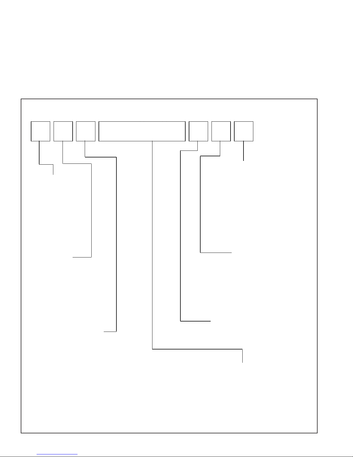
Cooking Nomenclature
J X T 9 1 3 6 C D P
Color
A Almond on Almond
Brand
A Amana
C Magic Chef
G Graffer &
Sattler
H Hardwick
J Jenn-Air
M Maytag
N Norge
U Universal
Y Crosley
Fuel
B Butane
D Dual Fuel
E/J Electric
G Gas, Natural
L Liquid Propane
M Microwave
P Standing Pilot
X No Fuel
W Warming Drawer
Product Type
A Accessory/Cartridge
C Cooktop Updraft/Countertop
D Downdraft Cooktop or Warming Drawer
E Eyelevel Range
G Grill
L Range (20")
M Range (36")
P Drop In (24")
Q Wall Oven (27 ")
R Range, Free-Standing (30")
S Slide-In (30")
T Range Hood
V OTR
W Wall Oven
Y RV Range
Z RV Top
6 16023510 ©2004 Maytag Services
B Black
C Brushed Chrome
H Traditional White
L Traditional Almond
P Prostyle
Q Monochromatic Bisque
S Stainless
T Traditional Bisque
W White on White
F Frost White (True Color White)
N Natural Bisque (True Color Bisque)
Listing
A UL/AGA
C CSA/CGA/CUL
D Dual Listed
G 220-240 V / 50-60 Hz
M Military Model
P PSB Approved
(Singapore)
X Export 120 V / 60 Hz
Production Code
This identifies the
production version.
Feature Content
1000-3999 Brands
4000-6999 Maytag/Amana
7000-9999 Jenn Air
General Information
Specifications
Refer to individual Technical Sheet for specification
information.
Placement of the Vent Hood
This electric vent hood must be placed in the kitchen or
comparable room. All safety guidelines must be followed
(see Chapter 2) and free air flow around the vent hood is
essential.
Do Not Block Air Vents
All air vents must be kept clear during cooking. If air
vents are covered during operation, the vent hood may
overheat.
Location of Model Number
To request service information or replacement parts, the
service center will require the model number of your vent
hood. This number can be found inside or under the vent
hood shroud.
For a permanently connected vent hood: This vent hood
must be connected to a grounded, metallic, permanent
wiring system, or an equipment grounding conductor
should be run with the circuit conductors and connected
to the equipment grounding terminal or lead on the
appliance.
WAR NI NG
!
Attaching adapter ground terminal to wall receptacle
cover screw does not ground the vent hood unless the
cover screw is metal and not insulated, and wall
receptacle is grounded through the house wiring.
Consumer should have circuit checked by a qualified
electrician to verify receptacle is properly grounded.
Model Identification
Complete enclosed registration card and promptly return.
If registration card is missing:
• For Jenn-Air product call 1-800-688-1100 or visit the
Web Site at www.jennair.com
• For product in Canada call 1-866-587-2002 or visit the
Web Site at www.jennair.com
When contacting provide product information located on
rating plate. Record the following:
Model Number: ___________________
Manufacturing Number: ___________________
Serial or S/N Number: ___________________
Date of purchase: ___________________
Dealer’s name and address: ___________________
Grounding Instructions
This vent hood must be grounded. If an electrical short
circuit occurs, grounding reduces the risk of electric
shock by providing an escape wire for the electric current.
The cord for this vent hood has a grounding wire with a
grounding plug. Put the plug into an outlet that is properly
installed and grounded.
WARNING
!
To avoid risk of electric shock, personal injury or death,
use grounding plug properly.
Ask a qualified electrician if you do not understand the
grounding instructions or if you wonder whether the vent
hood is properly grounded.
Keep the electrical power cord dry and do not pinch or
crush it in any way.
Service
Keep a copy of sales receipt for future reference or in
case warranty service is required. To locate an authorized
servicer:
• For Jenn-Air product call 1-800-688-1100 or visit the
Web Site at www.jennair.com
• For product in Canada call 1-866-587-2002 or visit the
Web Site at www.jennair.com
Warranty service must be performed by an authorized
servicer. We also recommend contacting an authorized
servicer, if service is required after warranty expires.
Parts and Accessories
Purchase replacement parts and accessories over the
phone. To order accessories for your product call:
• For Jenn-Air product call 1-800-688-1100 or visit the
Web Site at www.jennair.com
• For product in Canada call 1-866-587-2002 or visit the
Web Sites at www.amana.com or www.maytag.com
Extended Service Plan
We offer long-term service protection for this new oven.
• Dependability PlusSM Extended Service Plan is
specially designed to supplement Jenn-Air’s strong
warranty. This plan covers parts, labor, and travel
charges.
Call 1-800-925-2020 for information.
©2004 Maytag Services 16023510 7
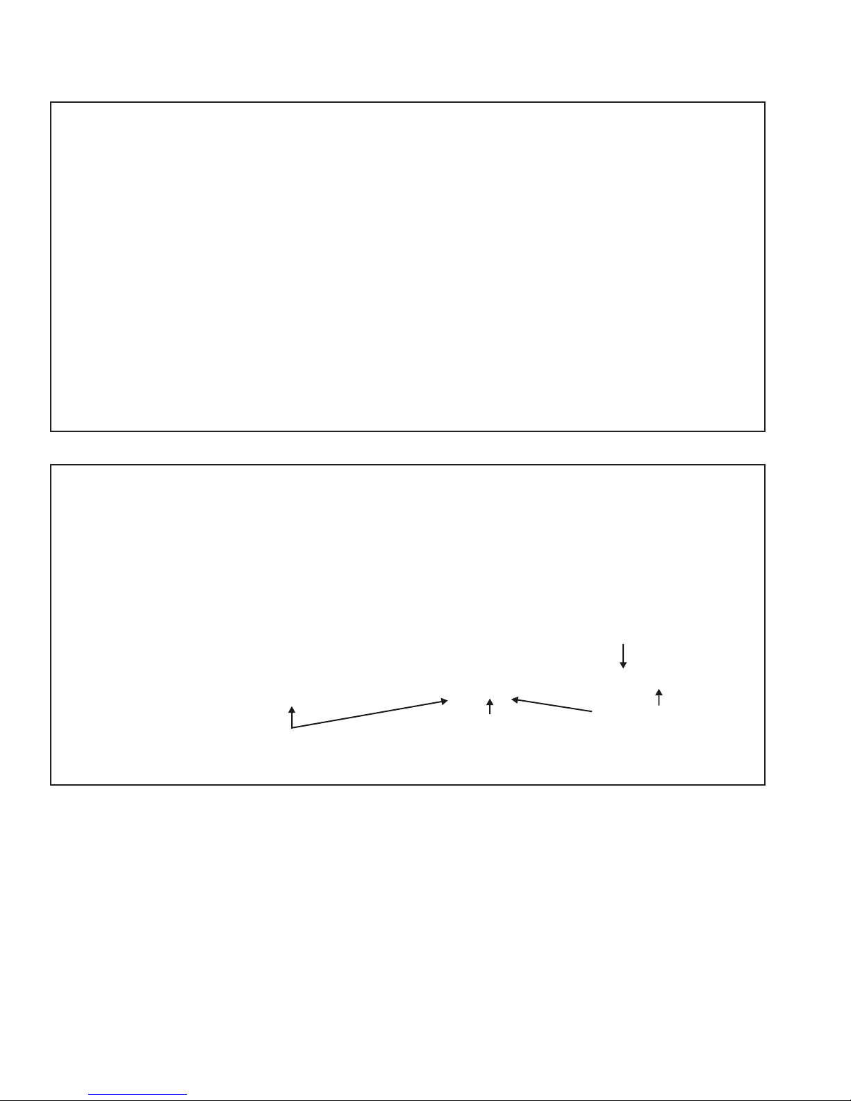
Range Description
Vent Hood Description
Filters/Filter Covers
Touch Pad/Control Pad
Halogen Lights
Blower Motor
Heat Lamps
Filters/Filter Covers
(in vent hood)
Touch Pad/Control Pad
Halogen Lights
Blower Motor
(in vent hood)
8 16023510 ©2004 Maytag Services
Troubleshooting Procedures
.
.
.
.
.
.
.
.
.
.
.
.
.
.
.
.
.
.
.
.
.
.
.
.
.
.
.
.
.
.
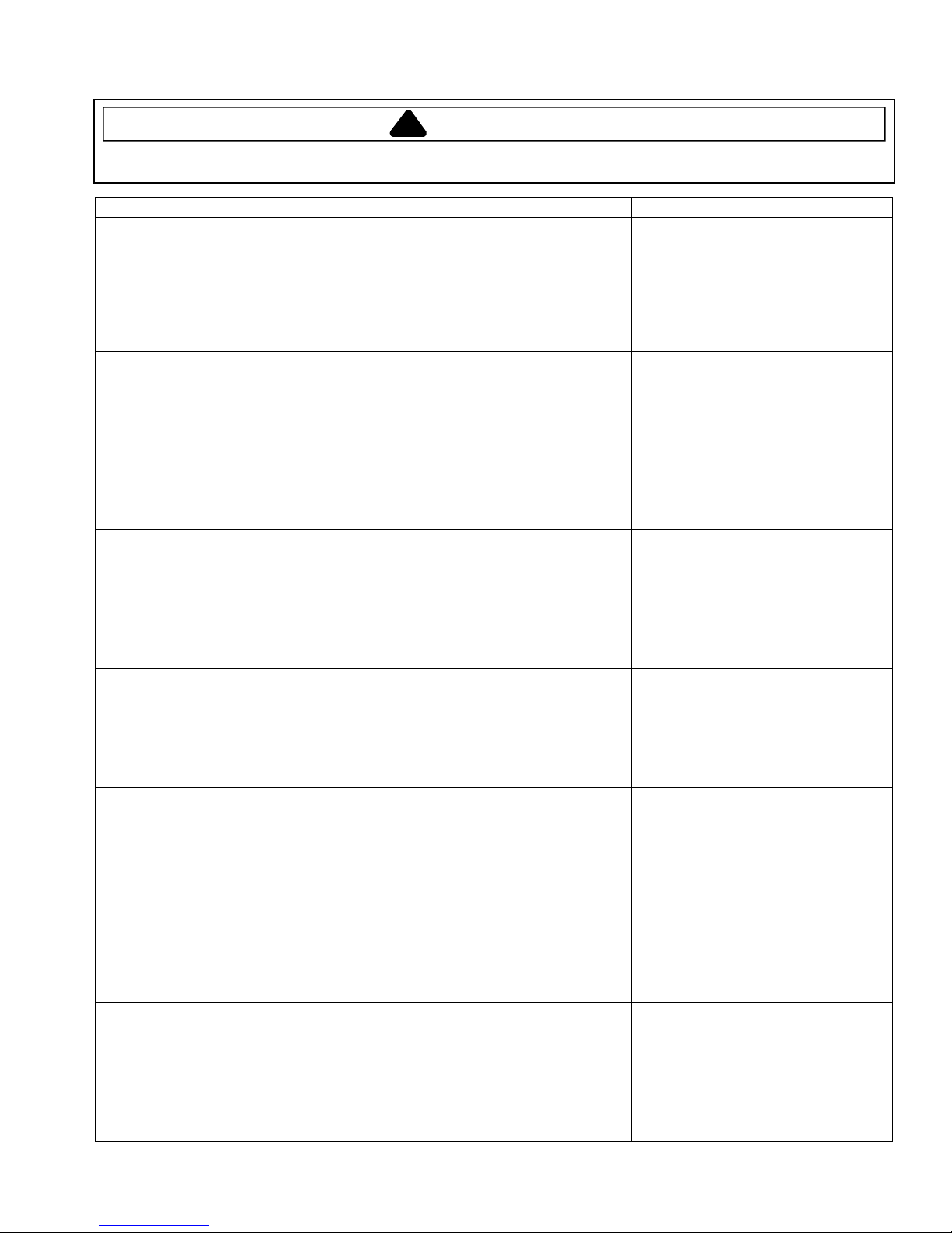
!
To avoid risk of electrical shock, personal injury, or death, disconnect power to vent hood before servicing, unless
testing requires power.
Problem Possible Cause Correction
Blower motor will not
operate, lights will not
illuminate
Blower motor will not operate
(Lights illuminate)
Blower motor starts slow and
will not operate at full speed
(Lights illuminate)
Blower motor operates, but
cannot change fan speed
(Lights illuminate)
Lights will not illuminate
(Blower motor operates)
Lights illuminate at full
brightness only
(Blower motor operates)
No input power ...............................................
Circuit breaker tripped ....................................
Black/white or white wires loose at control
board, no wires connected to control board...
Control board defective..................................
Touch pad/control panel defective .................
Blue wire loose on control board ....................
Blower motor seized.......................................
Blower motor defective...................................
Capacitor damaged or defective ....................
Touch pad or control panel defective.............
Blower motor too hot and has been shut
down by the thermal protection system..........
Capacitor shorted or defective .......................
Blower motor defective...................................
Control board defective..................................
Touch pad or control panel defective.............
Obstructions in blower motor .........................
Capacitor shorted or defective .......................
Blower motor defective...................................
Touch pad or control panel defective.............
Obstructions in blower motor .........................
Light bulb(s) burnt out ....................................
Light bulb not making contact with socket .....
Red wire loose on control board ....................
Touch pad or control panel defective.............
Light socket defective.....................................
Loose wires to lights/control board.................
Light socket defective.....................................
Control board defective..................................
Control panel defective ..................................
Touch pad or control panel defective.............
WARNING
• Verify 120 VAC is present at unit.
• Verify circuit breaker isn’t tripped.
• Verify all connections are tight.
• Perform control board test.
• Perform touch pad or control
panel test.
• Verify blue wire is connected and
tight on control board.
• Verify blower is free from
obstructions and rotates freely.
• Perform blower motor test.
• Perform capacitor test.
• Perform touch pad or control
panel test.
• Allow blower motor to cool.
• Perform capacitor test.
• Perform blower motor test.
• Perform control board test.
• Perform touch pad or control
panel test.
• Verify blower motor is free from
obstructions and rotates freely.
• Perform capacitor test.
• Perform blower motor test.
• Perform touch pad or control
panel test.
• Verify blower motor is free from
obstructions and rotates freely.
• Replace bulb(s).
• Remove power to unit, remove
light bulb and bend the two metal
brackets inside the bulb opening
(bend outwards). This lowers
the light socket.
• Verify red wire is connected and
tight on control board.
• Perform touch pad or control
panel test.
• Perform halogen light test.
• Verify wires are connected and
tight at light socket/control board.
• Perform halogen light test.
• Perform control board test.
• Replace control panel.
• Perform touch pad or control
panel test.
©2004 Maytag Services 16023510 9
Troubleshooting Procedures
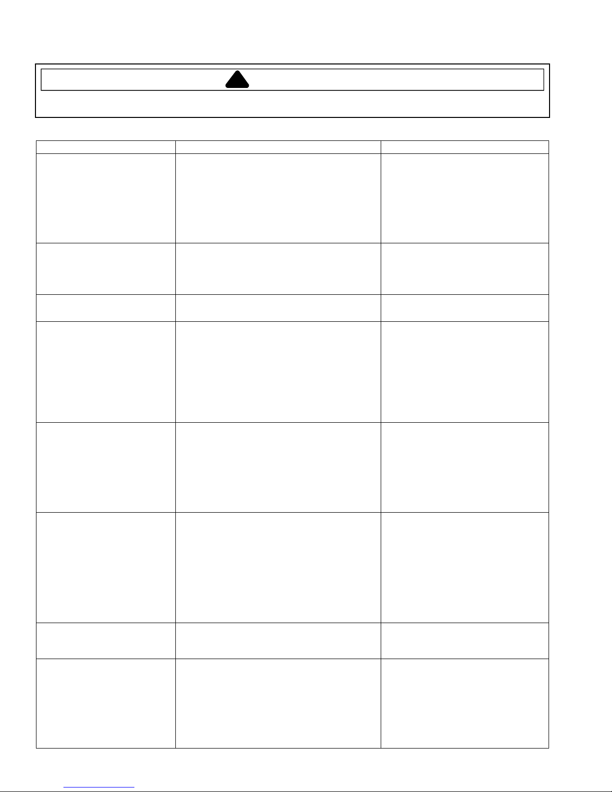
!
To avoid risk of electrical shock, personal injury, or death, disconnect power to vent hood before servicing, unless
testing requires power.
WARNING
Problem Possible Cause Correction
Lights illuminate at half
brightness only
(Blower motor operates)
Vent hood vibrates when
operating blower motor
Metal filter vibrates when
operating blower motor
Display will not illuminate No input power ...............................................
Heat lamp will not illuminate Heat lamp bulb defective................................
Dim display Loose wire connection or broken wire............
Any one single function on
control panel does not
operate
Vent hood not venting
properly
10 16023510
Loose wires to lights/control board.................
Light socket defective .....................................
Control board defective ..................................
Control panel defective...................................
Touch pad or control panel defective .............
Blower motor loose.........................................
Blower motor wheel damaged........................
Vent hood not securely fastened....................
Metal filter loose .............................................
Broken clip......................................................
Circuit breaker tripped ....................................
Loose wire connection or broken wire............
Control board defective ..................................
Touch pad or control panel defective .............
No input power ...............................................
Circuit breaker tripped ....................................
Loose wire connection or broken wire............
Touch pad or control panel defective .............
Control board requires a reset........................
Control board defective ..................................
Touch pad or control panel defective .............
Touch pad or control panel defective .............
Vent hood not close enough to cooktop.........
Open doors/windows affecting air flow...........
Ductwork clogged or blocked .........................
Duct opening restricted ..................................
Ductwork too small .........................................
• Verify wires are connected and
tight at light socket/control board.
• Perform halogen light test.
• Perform control board test.
• Perform control panel test.
• Perform touch pad or control
panel test.
• Tighten blower motor.
• Replace blower motor wheel.
• Verify vent hood installation;
tighten as necessary.
• Tighten or change metal filter.
• Replace the clip.
• Verify 120 VAC is present at unit.
• Verify circuit breaker isn’t tripped.
• Verify all connections are clean
and tight, wires are not broken.
• Verify voltage is present. If so,
perform control board test.
• Perform touch pad or control
panel test.
• Replace heat lamp bulb.
• Verify 120 VAC is present at unit.
• Verify circuit breaker isn’t tripped.
• Verify all connections are clean
and tight, wires are not broken.
• Perform touch pad or control
panel test.
• Verify all connections are clean
and tight, wires are not broken.
• Disconnect power to unit for 15
minutes. If still dim, replace the
control board.
• Verify voltage is present. If so,
test control board.
• Perform touch pad or control
panel test.
• Perform touch pad or control
panel test.
• Verify distance between hood
and cooktop (24-32 inches).
• Close all nearby doors and
windows.
• Clean the ductwork.
• Adjust the duct opening direction.
• Increase size of ductwork.
©2004 Maytag Services
Testing Procedures
.
.
.
.
.
.
.
.
.
.
.
.
.
.
.
.
.
.
.
.
.
.
.
.
.
.
.
.
.
.
.
.
!
WARNING
To avoid risk of electrical shock, personal injury or death; disconnect power to vent hood before servicing, unless
testing requires power.
Model Numbers Component Test Procedure Results
All Halogen lights
All Halogen light socket Remove one wire from receptacle and test
JXT9030CDP,
JXT9036CDP,
JXT9048CDP,
JXT9130CDP,
JXT9136CDP
JXT8030ADS,
JXT8036ADS,
JXT8042ADS,
JXT8136ADS,
JXT8142ADS,
JXT5830AD*,
JXT5836AD*
JXT9030CDP,
JXT9036CDP,
JXT9048CDP,
JXT9130CDP,
JXT9136CDP
JXT8030ADS,
JXT8036ADS,
JXT8042ADS,
JXT8136ADS,
JXT8142ADS,
JXT5830AD*,
JXT5836AD*
JXT9030CDP,
JXT9036CDP,
JXT9048CDP,
JXT9130CDP,
JXT9136CDP
Heat lamp socket Remove one wire from receptacle and test
Capacitor Disconnect wires. Measure resistance by
Capacitors
(2 ea, red wires input,
yellow wires output)
Transformer Check for input voltage by placing red
Transformer Check for input voltage by placing red
Press light switch once ................................
(measure voltage at light socket).................
Press light switch again...............................
(measure voltage at light socket).................
Press light switch once ................................
(measure voltage at light socket).................
Press and hold light switch for 3 seconds....
(measure voltage at light socket).................
resistance of terminals.................................
Measure voltage at light ..............................
resistance of terminals.................................
Measure voltage at light ..............................
placing red meter lead on positive
terminal, black meter lead on negative
terminal .......................................................
Reverse meter leads on capacitor
terminals......................................................
Check for a short by placing one lead on a
terminal and the other to ground..................
Obtain analog multi-meter. Disconnect
wires. Measure resistance by placing red
meter lead on positive terminal, black
meter lead on negative terminal ..................
Reverse meter leads on capacitor
terminals......................................................
Check for a short by placing one lead on a
terminal and the other to ground..................
lead on black wire (input voltage), black
lead on white wire (neutral)..........................
Check transformer outputs by placing leads
on black (input voltage) and white (neutral),
then set fan speed as follows:
6 ..................................................................
5 ..................................................................
4 ..................................................................
3 ..................................................................
2 ..................................................................
1 ..................................................................
lead on brown wire (input), black lead on
light blue wire (neutral) ................................
Check transformer outputs by placing
meter leads on:
Brown (Input voltage) ..................................
Black ...........................................................
Red..............................................................
Orange ........................................................
Yellow..........................................................
Green (Lowest setting) ................................
Lights illuminate to full brightness
(120 VAC).
Lights extinguish (turn off)
(0 VAC).
Lights illuminate to full brightness
(120 VAC).
Lights illuminate to half brightness
(63 VAC)
Indicates continuity with bulb screwed in.
120 VAC. If no voltage is present at
light, check wiring or light switches.
Indicates continuity with bulb screwed in.
120 VAC. If no voltage is present at
light, check wiring or light switches.
Meter reading should gradually increase
(capacitor charging).
Meter reading should gradually decrease
(capacitor discharging).
Infinity (if shorted, replace capacitor).
Rating: 4 microfarad
Meter reading should gradually increase
(capacitor charging).
Meter reading should gradually decrease
(capacitor discharging).
Infinity (if shorted, replace capacitor).
120 VAC
113 VAC
88 VAC
80 VAC
66 VAC
50 VAC
33 VAC
120 VAC
120 VAC
106 VAC
97 VAC
90 VAC
81 VAC
74 VAC
©2004 Maytag Services 16023510 11
 Loading...