

Jenn-Air JXT19130CDP, JXT19136CDP Installation Manual
RANGE HOOD
ModeJ Number:
Manufacturer Number:
Size:
.[×19130CDP
MK753_}
30"
[×19136CDP
MK7536
36"
GUIDE
TABLE OF CONTENTS
Satet, Instructions .................................................... 1
MountinR Heights ................................................... 2
[)uctin¢ .............................................................. 3-7-8
Specifications ........................................................... 4
Installation ............................................................ 5-6
F:orm No. A/06/04 Part No. 8110P262-60 ,¢2004 Maytag Appliances Sales (o. litho U.S.A.
MODELS: JXT9130 J×T9136
Installation
Theinstallationin thismanuarisintendedforquarifiedinstallers,servicetechniciansor persons
withsimilarqualifiedbackground.DONOTattempttoinstarlthisapplianceyourserf,rniurycourd
resurtfrominstallingtheunitdueto rackofappropriateerectricalandtechnicalbackground.
Air erectricar wiring must be properly installed, insulated and grounded. Overly accumulated
greasein old duct work should becleaned out orduct work should be replaced if necessaryto
avoid the possibility of agrease fire. Checkall ioints on duct work to insure proper connection
andallioints should be properly taped.
* Please check for latest specification revisions before any custom work or cutouts.
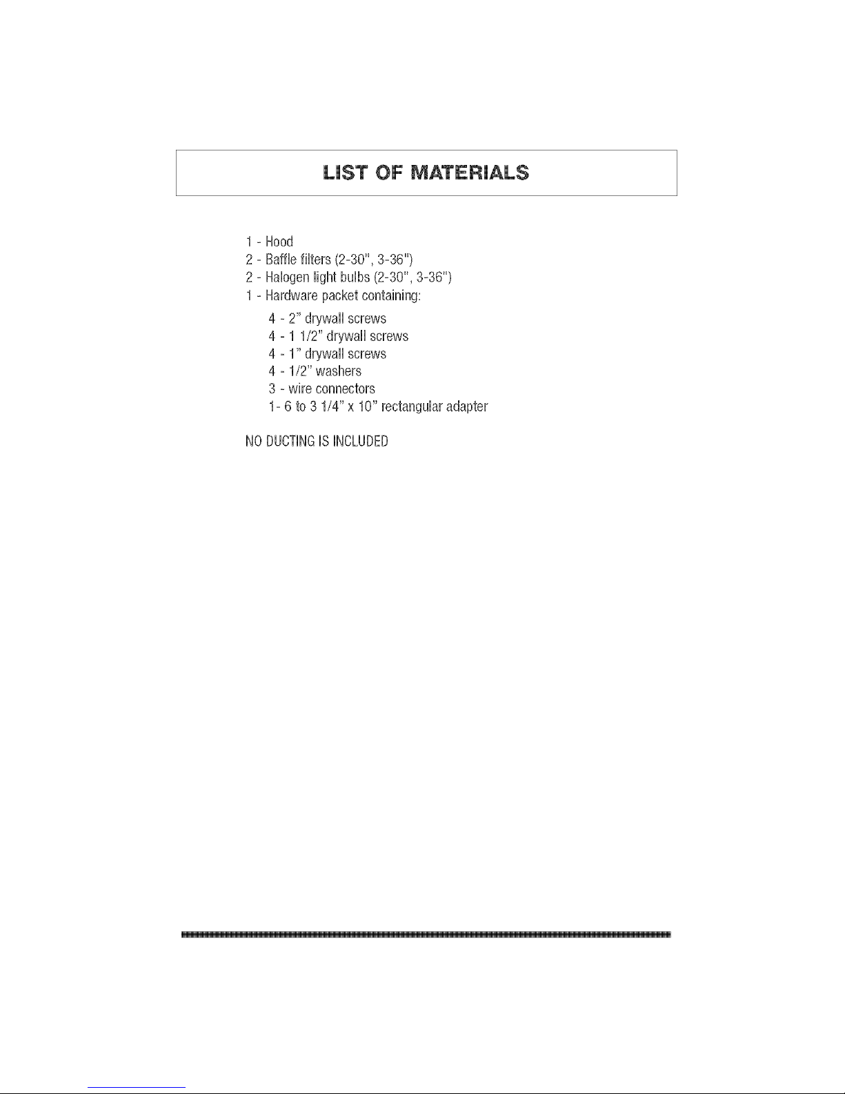
LiST OF MATERIALS
=
2=
2=
1=
Hood
Bafflefilters (2°30", 3°36")
Halogenlight bulbs (2°30", 3-36")
Hardwarepacketcontaining:
4 ° 2" drywall screws
4 ° 1 1/2" drywall screws
4 ° 1" drywall screws
4 ° 1/2" washers
3 °wire connectors
1° 6 to 3 1/4" x 10" rectanguhr adapter
NODUOTINGISINCLUDED
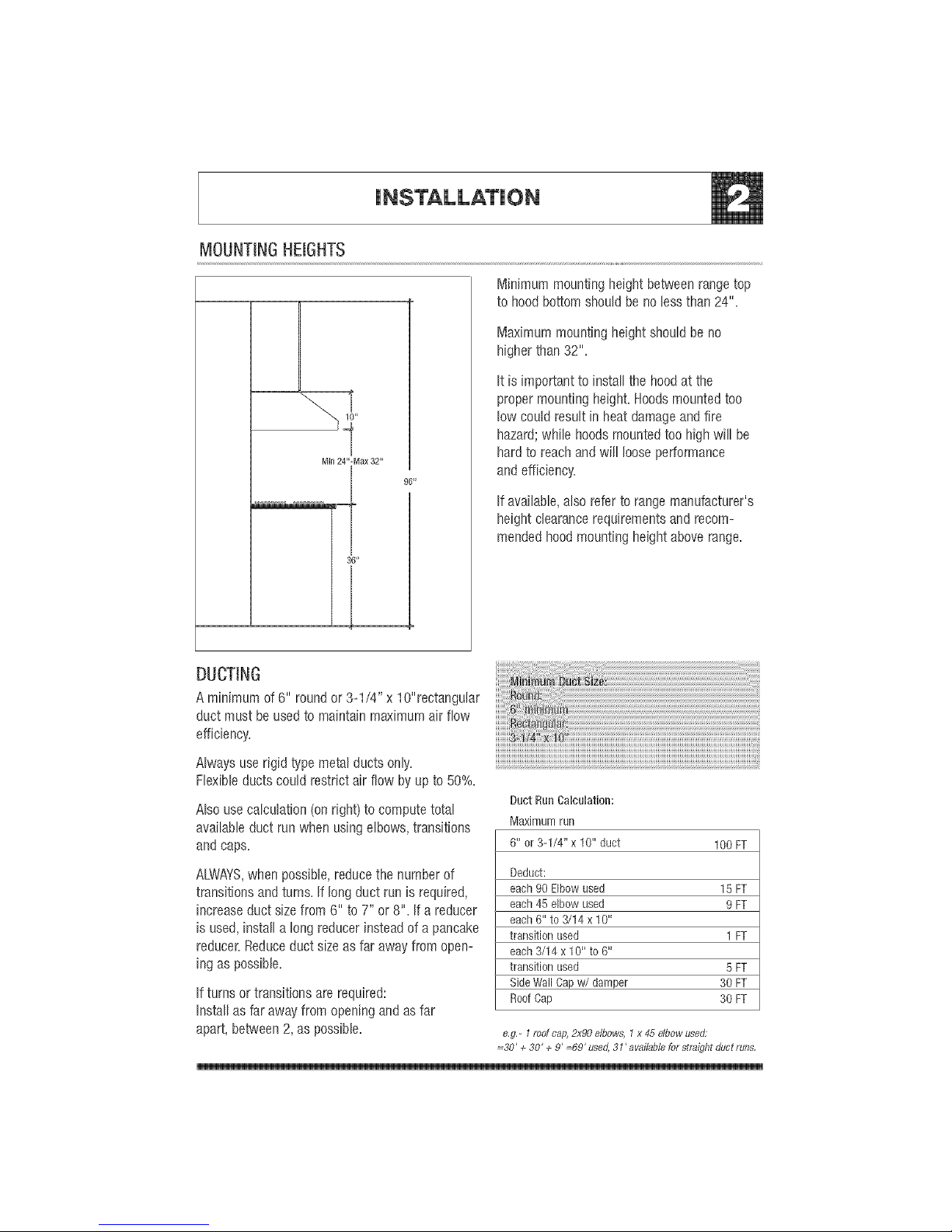
MOUNTINGHEIGHTS
96"
Minimum mounting height between rangetop
to hood bottomshouMbenotess than 24".
Maximum mounting height shourdbe no
higher than 32".
rt is important to instarlthe hoodat the
proper mounting height. Hoodsmounted too
row couM result in heat damageand fire
hazard; while hoods mounted too high will be
hard to reach and will rooseperformance
and efficiency.
ff available, arso refer to range manufacturer's
height clearance requirements and recom-
mended hoodmounting height above range.
DUCTING
A minimum of 6" roundor 3-1/4" x lO"rectangurar
duct must be usedto maintain maximum air flow
efficiency.
Alwaysuserigidtypemetalductsonly,
Flexibleductscouldrestrictair flowbyupto 50%.
Also use calculation (on right) to compute total
availableduct run when using elbows, transitions
andcaps.
ALWAYS,when possible, reducethe number of
transitions and turns. If long duct run is required,
increase duct size from 6" to 7" or 8". If a reducer
is used, install a long reducer instead of a pancake
reducer.Reduceduct size as far away from open°
ing as possible.
If turns or transitions are required:
Install as far away from opening and asfar
apart, between 2, as possible.
Duct RunCalculation:
Maxirnulnrun
6" or 3-1/4' x 10" duct
100FT
Deduct:
each90 Elbowused 15 FT
each45 elbow used 9 FT
each6" to "Y14x 10"
transition used 1 FT
each3/14 x 10" to 6"
transition used 5 FT
SideWallCapw/damper 30 FT
RoofCap 30 FT
e,g,- 1 roof cap, 2x90 elbows, t x 45 elbow used;
=30' + 30' + 9' =69' used, 31' available for stroiqht duct runs,
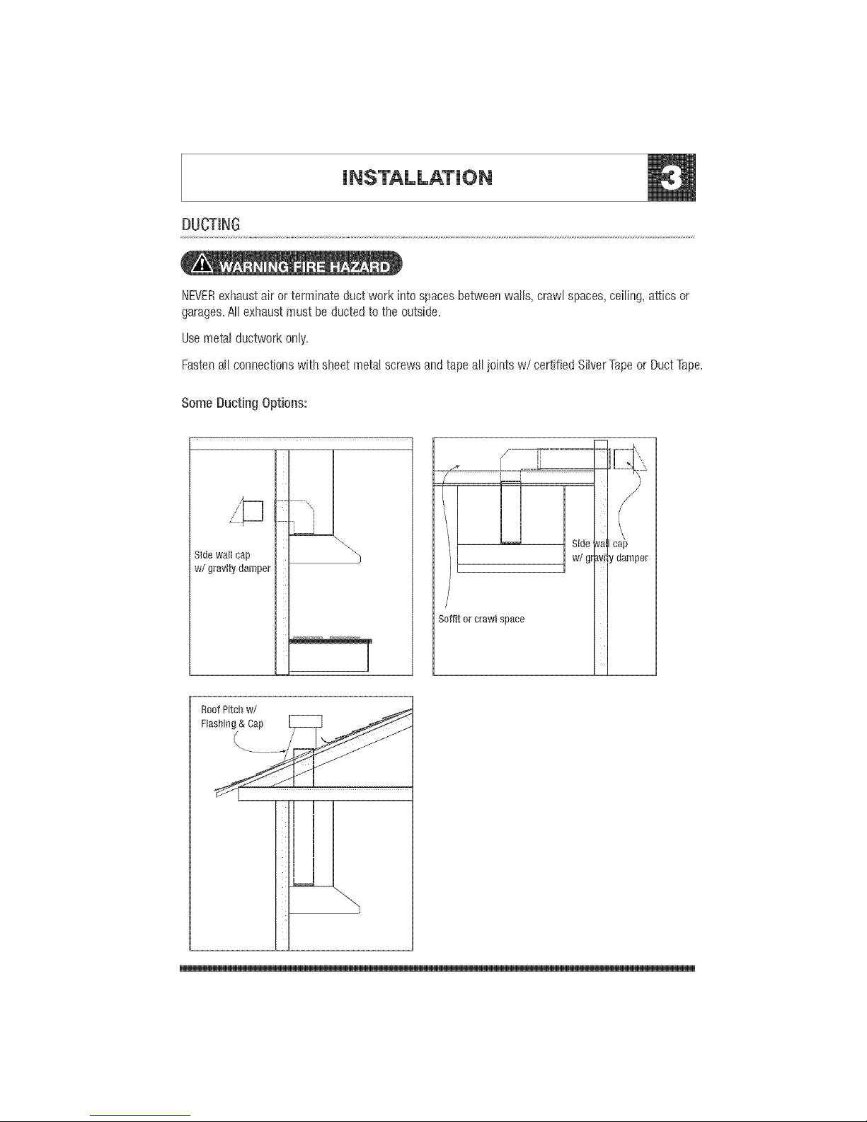
DUCTING
NEVERexhaustair or terminate duct work into spaces betweenwalls, crawl spaces,ceiling, attics or
garages.Airexhaust must be ducted to theoutside.
Usemetal ductwork onry.
FastenaHconnections with sheet metal screws and tape aHjoints w/certified SHyerTapeor Duct Tape.
SomeDucting Options:
Sidewallcap
w/gravitydamper
i
/- T"
[ I
I r .---L.
n H
! !
SideNa
w/gtavi:ydamper
Soffitor crawl space
RoofPitch w/
Flashing& Cap
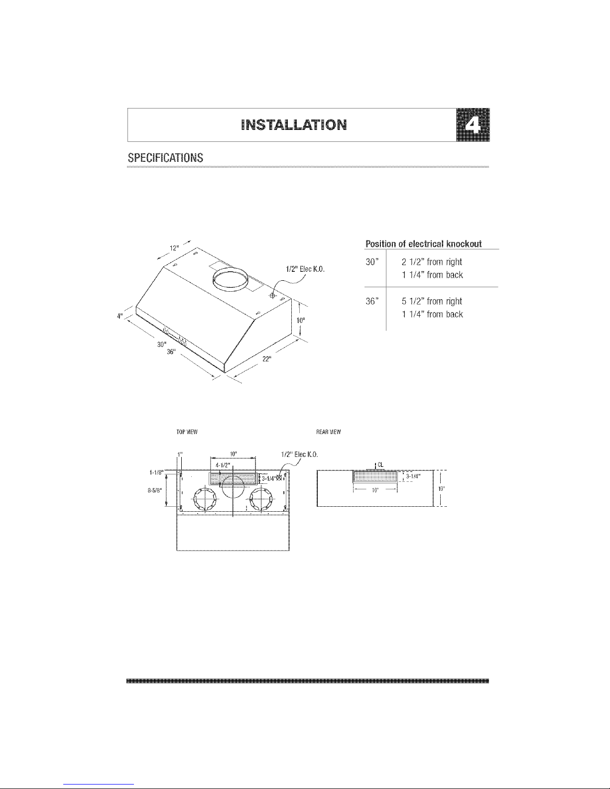
SPECIFICATIONS
4"J
Positionof electricalknockout
30" 2 1/2"fromright
1 1/4"fromback
36" 5 1/2"fromright
1 1/4"fromback
TORVIEW REARVIEW
1-1/R"_
8o5/8"
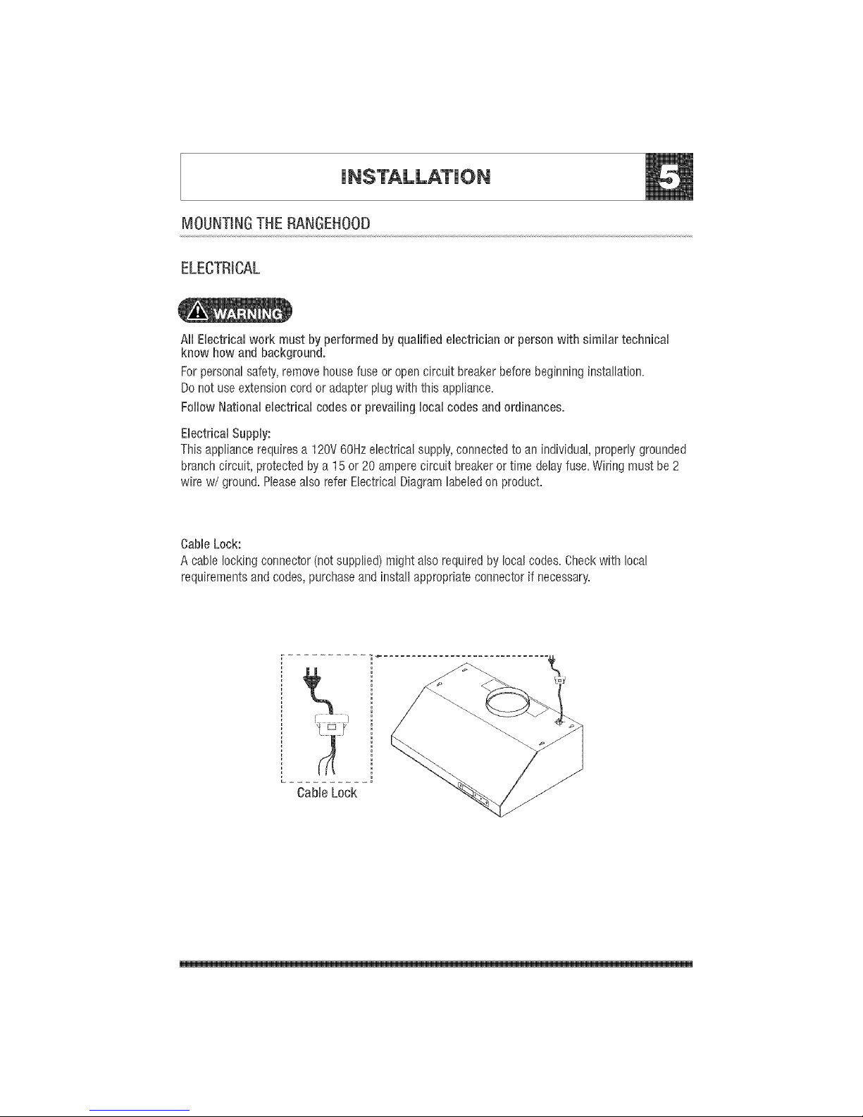
MOUNTINGTHE IANGEHOOD
ELECTRICAL
All Electricalworkmustbyperformedbyqualifiedelectricianor personwith similartechnical
knowhowandbackground.
Forpersonalsafety,removehousefuseoropencircuitbreakerbeforebeginninginstallation+
Donot useextensioncordoradapterplugwiththis appliance+
FollowNationalelectricalcodesor prevailng localcodesandordinances.
ElectricalSupply:
Thisappliancerequiresa 120V60Hzelectricalsupply,connectedtoanindividual,properlygrounded
branchcircuit,protectedbya 15or20amperecircuitbreakeror timedelayfuse:Wiringmustbe2
wirew/ground:PleasealsoreferElectricalDiagramlabeledonproduct:
Cable Lock:
A cable locking connector (not supplied) might also required by local codes. Checkwith local
requirements and codes, purchaseand install appropriate connector if necessary.
J
L ..........
CableLock

MOUNTINGTHE RANGEHOOD
1. This range hood is mounted undera
kitchen cabinet unit.
2. Selectpreferred duct location on rear or
top of unit. (Seepage6 & 7 for ducting
conversion options)
3. Begin installation by temporarily removing
the baffle filters.
4. Reinforcecabinet basewith lx2 wood
strips if additional strengthening is
required.
5. Temporarilyposition the range hood in
the desired mounting location.
Measure and mark the mounting holes,
duct and electrical access locations with
a pencil.
6. Drill/cut out the required openings for
duct and electrical access; make sure the
duct opening is large enoughto apply
duct tape.
7. Fastenhood onto cabinet with screws
and washers provided.
8. Install electrical.
9. Install duct work and duct-tape.
10. Reinstall the baffle filters.
11. Power up hood andcheck for leaks
around duct-tape.
6, Duct
opening
cutout
/
4. Add lx2
woodstrips

CONVERTIBLEOPTIONS
This rangehood is equipped with the option of a 6" verticar discharge,3 1/4"x10" vertical discharge,
or 3 1/4"x10" rear discharge.Additionar accessories are provided to convert to either of the above
discharge methods.
Convertible Options
Verticardischarge 6" round
Verticardischarge 3 1/4"xl 0"
Horizontalrear discharge 3 1/4"xl 0"
Convertible Accesories
Roundto rectangurartransition adaptor
Rectangurarto round transition adaptor (pre-mounted)
Gasket(pre°mounted)
Rectangurarrear cap (pro-mounted)
3 1/4"x10" starting corrar
3 1/4"x10" Vertical Discharge
1.Removepro-mounted 6"transition adaptoror duct
opening,Leaveattachedgasketin its originalplace.
3. Mount the3-1/4"x10" starting collaron top of
transition piecewith remainingscrews.
2, Placerectangular transitionadaptor asshown over
gasketand by first installing 4screws on Ilalf round
section,
 Loading...