

Jenn-Air JXL6536HSS Installation Manual

36" (91.4 CM) HOOD LINER
IMPORTANT: READ AND SAVE THESE INSTRUCTIONS.
FOR RESIDENTIAL USE ONL
IMPOR
POUR UTILISA
.
CAISSE DE HOTTE
36" (91,4 CM)
Installation Instructions and Use & Care Guide
For questions about features, operation/performance, parts, accessories, or service in the U.S.A., call:
1-800-JENNAIR (1-800-536-6247), or visit our website at www.jennair.com.
In Canada, call: 1-800-JENNAIR (1-800-536-6247), or visit our website at www.jennair.ca.
Instructions d’installation et Guide d’utilisation et d’entretien
Au Canada, pour assistance, installation ou service, composez le 1-800-JENNAIR (1-800-536-6247) ou visitez notre site web
Table of Contents/Table des matières ..................................... 2
Y.
TANT : LIRE ET CONSERVER CES INSTRUCTIONS.
TION RÉSIDENTIELLE UNIQUEMENT
LI310B/W11280190B
à www.jennair.ca.
TABLE OF CONTENTS TABLE DES MATIÈRES
RANGE HOOD SAFETY .................................................................2
INSTALLATION REQUIREMENTS .................................................4
Tools and Parts .............................................................................4
Location Requirements ................................................................4
Venting Requirements ..................................................................5
Electrical Requirements ...............................................................6
INSTALLATION INSTRUCTIONS ...................................................7
Prepare Location ..........................................................................7
Install Hood Liner Internal Blower Motor .....................................8
Install Hood Liner In-Line (External Type) Blower Motor ........... 10
Make Electrical Connections for In-Line Blower Motor
System........................................................................................11
Make Electrical Power Supply Connection to Hood Liner ........12
Complete Installation and Check Operation .............................13
RANGE HOOD USE ......................................................................14
Range Hood Controls ................................................................14
RANGE HOOD CARE ...................................................................15
Cleaning .....................................................................................15
WIRING DIAGRAM .......................................................................16
ASSISTANCE OR SERVICE .........................................................17
In the U.S.A. ..............................................................................17
In Canada ...................................................................................17
Accessories ................................................................................17
SÉCURITÉ DE LA HOTTE DE CUISINIÈRE ...............................18
EXIGENCES D’INSTALLATION ...................................................19
Outils et pièces ...........................................................................19
Exigences d’emplacement .........................................................19
Exigences concernant l’évacuation ...........................................21
Spécications électriques ..........................................................22
INSTRUCTIONS D’INSTALLATION .............................................23
Préparation de l’emplacement ...................................................23
Installation du moteur du ventilateur interne de
la caisse de la hotte ...................................................................24
Installation du moteur du ventilateur en ligne (externe)
de la caisse de la hotte .............................................................26
Réalisation des connexions électriques du système du moteur
du ventilateur en ligne ................................................................27
Réalisation des connexions de l’alimentation électrique à
la caisse de la hotte ...................................................................29
Achever l'installation et vérier le fonctionnement ....................29
UTILISATION DE LA HOTTE .......................................................30
Commandes et caractéristiques ................................................30
ENTRETIEN DE LA HOTTE .........................................................31
Nettoyage ...................................................................................31
SCHÉMA DE CÂBLAGE ...............................................................32
ASSISTANCE OU SERVICE .........................................................33
Au Canada ..................................................................................33
Accessoires ................................................................................33
RANGE HOOD SAFETY
Your safety and the safety of others are very important.
We have provided many important safety messages in this manual and on your appliance. Always read and obey all safety
messages.
This is the safety alert symbol.
This symbol alerts you to potential hazards that can kill or hurt you and others.
All safety messages will follow the safety alert symbol and either the word “DANGER” or “WARNING.”
These words mean:
You can be killed or seriously injured if you don't immediately
DANGER
WARNING
All safety messages will tell you what the potential hazard is, tell you how to reduce the chance of injury, and tell you what can
happen if the instructions are not followed.
follow instructions.
You
can be killed or seriously injured if you don't
instructions.
follow
2
IMPORTANT SAFETY INSTRUCTIONS
READ AND SAVE THESE INSTRUCTIONS
3
INSTALLATION REQUIREMENTS
Tools and Parts
Gather the required tools and parts before starting installation.
Read and follow the instructions provided with any tools listed
here.
Tools needed
■ Level
■ Drill
■ 1¼" (3.0 cm) drill bit
■ 1/8" (3 mm) drill bit
■ Pencil
■ Wire stripper or utility knife
■ Tape measure or ruler
■ Pliers
■ Caulking gun and weatherproof caulking compound
■ Vent clamps
■ Jigsaw or keyhole saw
■ Flat-blade screwdriver
■ Metal snips
■ Phillips screwdriver
Parts needed
■ Home power supply cable
1
■ 1
/2" (1.3 cm) UL listed or CSA approved strain relief
■ 3 UL listed wire connectors
■ 1 wall or roof cap
■ Metal vent system
■ Blower motor system - internal or external (see “Blower Motor
System” in the “Accessories” section).
Location Requirements
IMPORTANT: Observe all governing codes and ordinances.
Have a qualied technician install the hood liner. It is the
installer's responsibility to comply with installation clearances
specied on the model/serial rating plate. The model/serial rating
plate is located behind the left lter on the rear wall of the hood
liner.
The hood liner location should be away from strong draft areas,
such as windows, doors and strong heating vents.
Cabinet opening dimensions that are shown must be used. Given
dimensions provide minimum clearance.
The hood liner must be surrounded by a custom built enclosure
with hood support capable of supporting 75 lb (34 kg).
This hood liner is recommended for use with cooktops with a
maximum total rating of 105,000 Btus or less.
Grounded electrical outlet is required. See “Electrical
Requirements” section.
All openings in ceiling and wall where canopy hood will be
installed must be sealed.
For Mobile Home Installations
The installation of this range hood must conform to the
Manufactured Home Construction Safety Standards, Title 24
CFR, Part 328 (formerly the Federal Standard for Mobile Home
Construction and Safety, Title 24, HUD, Part 280) or when such
standard is not applicable, the standard for Manufactured Home
Installation 1982 (Manufactured Home Sites, Communities and
Setups) ANSI A225.1/NFPA 501A, or latest edition, or with local
codes.
Cabinet Dimensions
36" (91.4 cm) cabinet opening
42" (106.7 cm) cabinet opening*
48" (121.9 cm) cabinet opening*
Parts supplied
Remove parts from packages. Check that all parts are included.
■ 2 metal grease lters
■ Hood liner with halogen lamps installed.
■ 1 - 10" (25.4 cm) square to 10" (25.4 cm) round duct
transition with damper.
■ 4 - 5 x 45 mm mounting screws
■ 4 - 4.2 x 8 mm screws
22" (55.9 cm)
Hood support must be
capable of supporting
75 lb (34 kg)
“X“ bottom
of canopy to
cooking surface
hood liner depth
*Spacer kit required
IMPORTANT:
Minimum distance “X”: 24" (61 cm) from electric cooking
surfaces.
Minimum distance “X”: 30" (76.2 cm) from gas cooking surfaces.
Suggested maximum distance “X”: 36" (91.4 cm).
4
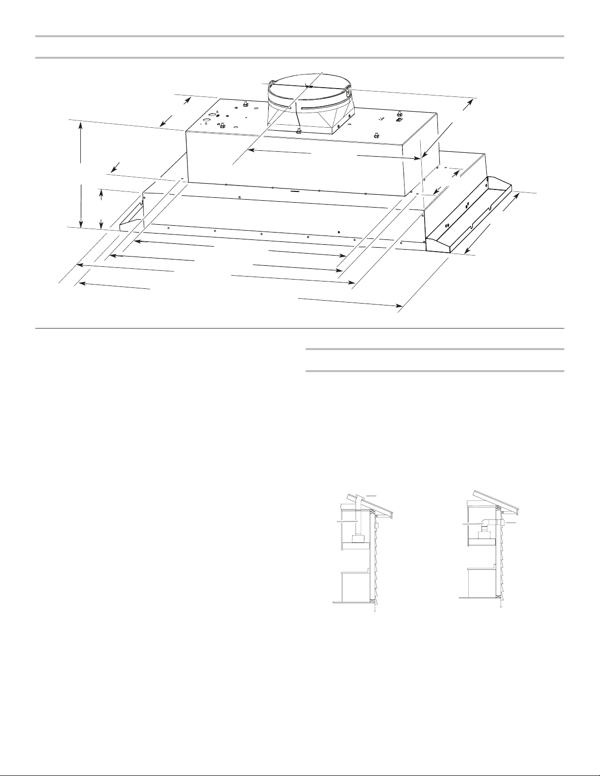
Installation Dimensions
12³⁄₈"
(31.4 cm)
11" (27.9 cm)
4¹³⁄₁₆" (12.2 cm)
11¹⁄₂"
(29.2 cm)
5¹⁄₁₆"
(12.8 cm)
27⁵⁄₈" (70.1 cm)
29¹³⁄₁₆" (75.8 cm)
35⁷⁄₈" (91.1 cm)
41⁷⁄₈" (106.4 cm) with 42" (106.7 cm) spacer kit
47⁷⁄₈" (121.6 cm) with 48" (121.9 cm) spacer kit
Venting Requirements
■ Vent system must terminate to the outdoors.
■ Do not terminate the vent system in an attic or other enclosed
area.
■ Do not use 4" (10.2 cm) laundry-type wall caps.
■ Use metal vent only. Rigid metal vent is recommended.
Plastic or metal foil vent is not recommended.
■ The length of vent system and number of elbows should be
kept to a minimum to provide efcient performance.
For the most efficient and quiet operation:
■ Use no more than three 90° elbows.
■ Make sure there is a minimum of 24" (61.0 cm) of straight
vent between the elbows if more than 1 elbow is used.
■ Do not install 2 elbows together.
■ Use vent clamps to seal all joints in the vent system.
■ Use caulking to seal exterior wall or roof opening around the
cap.
■ The size of the vent should be uniform.
18" (45.7 cm)
10¹⁄₈" (25.7 cm)
22" (55.9 cm)
Venting Methods
Typical Internal Blower Motor System Venting
Installations
A 10" (25.4 cm) round vent system is needed for installation (not
included). The hood exhaust opening is 10" (25.4 cm) round.
NOTE: Flexible vent is not recommended. Flexible vent
creates back pressure and air turbulence that greatly reduce
performance.
Vent system can terminate either through the roof or wall. To vent
through the wall, a 90° elbow is needed.
Roof Venting Wall Venting
B
A
A
B
Cold weather installations
An additional back draft damper should be installed to minimize
backward cold air ow and a thermal break should be installed to
minimize conduction of outside temperatures as part of the vent
system. The damper should be on the cold air side of the thermal
break.
The break should be as close as possible to where the vent
system enters the heated portion of the house.
Makeup air
Local building codes may require the use of makeup air systems
when using ventilation systems greater than specied CFM of
air movement. The specied CFM varies from locale to locale.
Consult your HVAC professional for specic requirements in your
area.
A. 10" (25.4 cm) round vent
B. Roof cap
A. 10" (25.4 cm) round vent
B. Wall cap
5
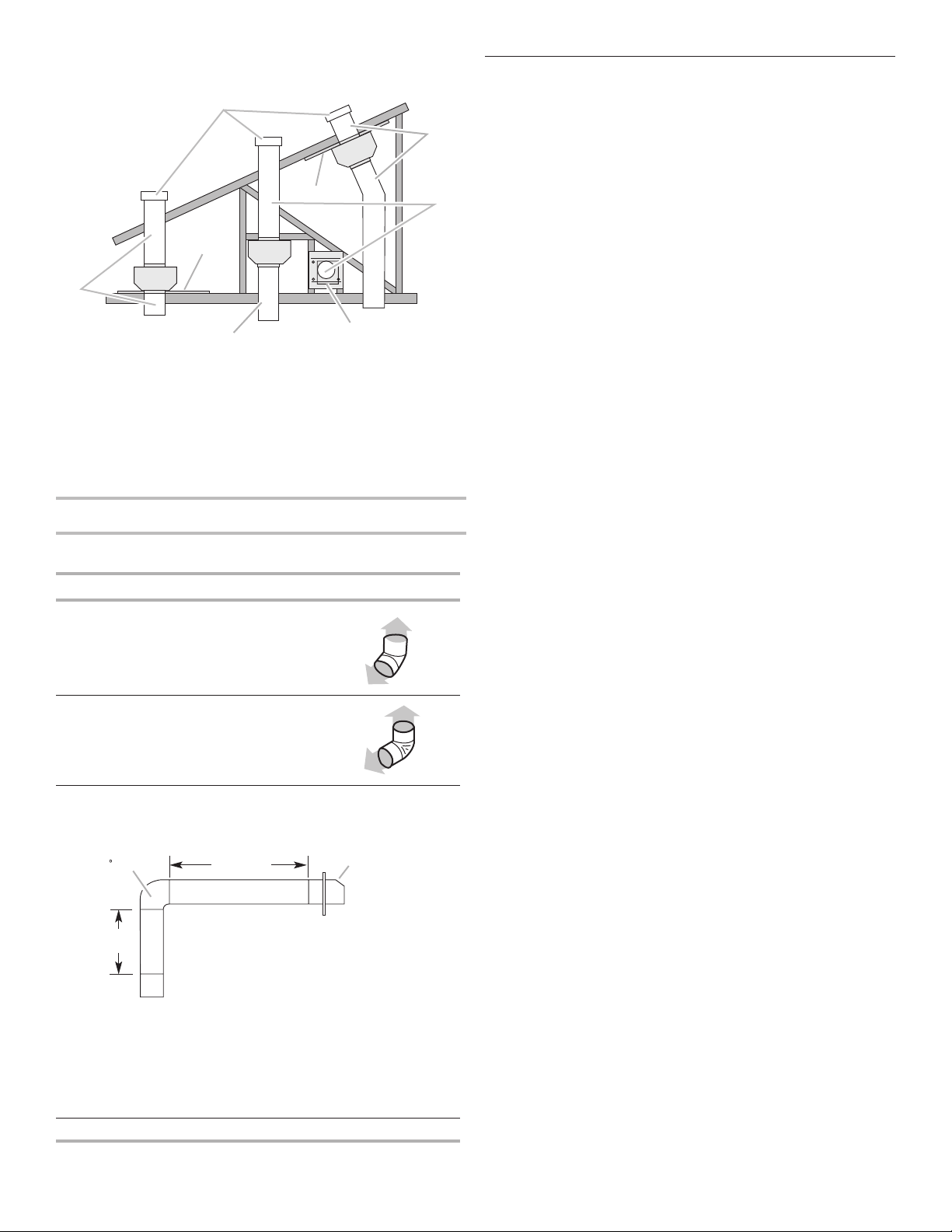
Typical In-line Blower Motor System Venting
A
A
C
A
90 elbo
Wall cap
Installations
A
E
D
D
B
F
G
H
A. 10" (25.4 cm) round vent
B. Mount on top of ceiling joists.
C. Roof caps
D. Plywood (optional for some installations)
E. Mount on underside of roof rafters.
F. Mount from cross-members tied to trusses.
G. Duct horizontal; mount to cross-members
tied to trusses.
H. Wall cap
Calculating Vent System Length
To calculate the length of the system you need, add the
equivalent feet (meters) for each vent piece used in the system.
Vent Piece Equivalent Length
45° elbow 2.5 ft
(0.8 m)
Electrical Requirements
Observe all governing codes and ordinances.
Ensure that the electrical installation is adequate and in
conformance with National Electrical Code, ANSI/NFPA 70 (latest
edition), or CSA Standards C22.1-94, Canadian Electrical Code,
Part 1 and C22.2 No. 0-M91 (latest edition) and all local codes
and ordinances.
If codes permit and a separate ground wire is used, it is
recommended that a qualied electrician determine that the
ground path is adequate.
A copy of the above code standards can be obtained from:
National Fire Protection Association
1 Batterymarch Park
Quincy, MA 02169-7471
CSA International
8501 East Pleasant Valley Road
Cleveland, OH 44131-5575
■ A 120 V, 60 Hz, AC only, 15 A, fused electrical circuit is
required.
■ If the house has aluminum wiring, follow the procedure
below:
Connect the aluminum wiring using special connectors and/or
tools designed and UL listed for joining copper to aluminum.
Follow the electrical connector manufacturer's recommended
procedure. Aluminum/copper connection must conform with local
codes and industry accepted wiring practices.
■ Wire sizes and connections must conform with the rating of
the appliance as specied on the model/serial rating plate.
The model/serial plate is located behind the lter on the rear
wall of the range hood.
■ Wire sizes must conform to the requirements of the National
Electrical Code, ANSI/NFPA 70 (latest edition), or CSA
Standards C22. 1-94, Canadian Electrical Code, Part 1 and
C22.2 No. 0-M91 (latest edition) and all local codes and
ordinances.
90° elbow 5.0 ft
(1.5 m)
The maximum equivalent vent lengths are:
10" (25.4 cm) round vents - 60 ft (18.3 m)
Example vent system
w
2 ft
(0.6 m)
The following example falls within the maximum recommended
vent length.
1 - 90° elbow = 5.0 ft (1.5 m)
1 - wall cap = 0.0 ft (0.0 m)
8 ft (2.4 m) straight = 8.0 ft (2.4 m)
Length of system = 13.0 ft (3.9 m)
6 ft (1.8 m)
6
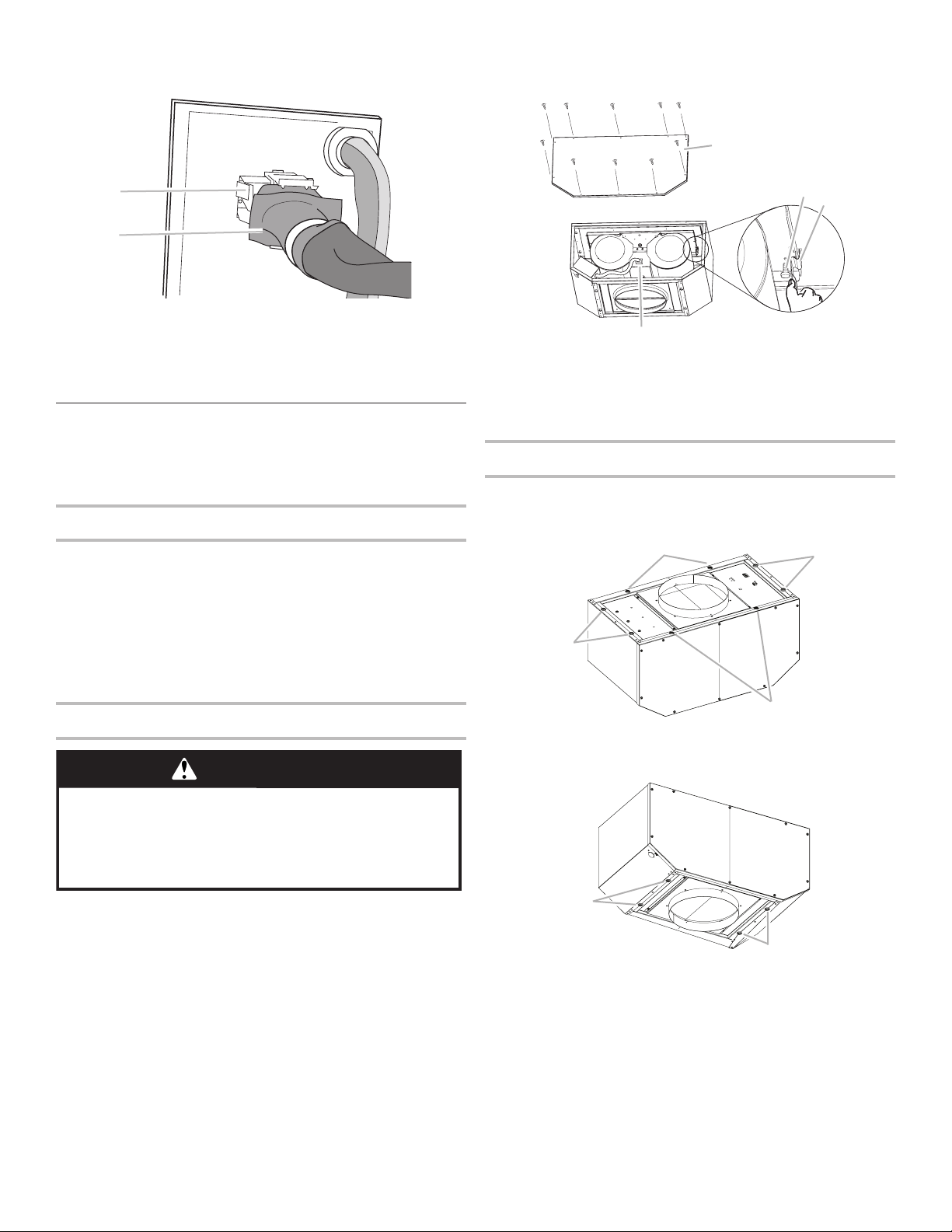
INSTALLATION INSTRUCTIONS
B
C
F
G
Prepare Location
■ It is recommended that the vent system be installed before
the hood is installed.
■ Before making cutouts, make sure there is proper clearance
within the ceiling or wall for exhaust vent.
■ Hood liner is to be installed 24" (61.0 cm) minimum for
electric cooking surfaces, 30" (76.2 cm) minimum for gas
cooking surfaces, to a suggested maximum of 36" (91.4 cm)
above the cooking surface.
■ Check that all installation parts have been removed from the
shipping carton.
1. Disconnect power.
2. Determine which venting method to use: roof or wall exhaust.
3. Select a at surface for assembling the range hood. Place
covering over that surface.
WARNING
Excessive Weight Hazard
Use two or more people to move and install
range hood.
Failure to do so can result in back or other injury.
4. Using 2 or more people, lift hood liner onto covered surface.
5. Remove the lters. See the “Range Hood Care” section.
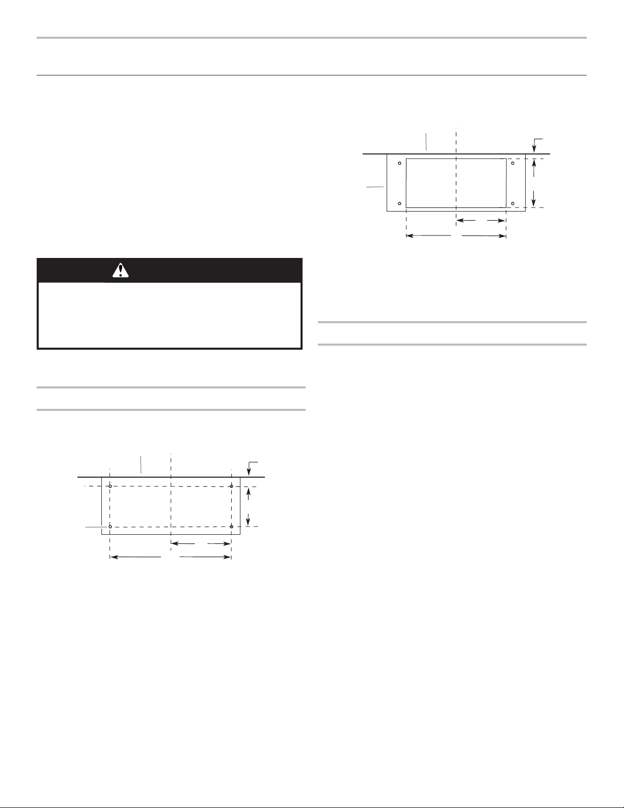
Hood Liner Support Preparation
1. Mark the locations for the four 1/8" (3 mm) diameter holes on
the hood support as shown.
A
G
A. Wall
B. Centerline
C. 6" (15.2 cm)
D. 10¹⁄8" (25.7 cm)
B
C
D
E
F
E. 1415⁄16" (38.0 cm)
F. 29¹³⁄16" (75.8 cm)
G. 1⁄8" (3 mm) hole
diameter
3. Mark the cutout for the rectangular clearance hole for the
upper hood liner housing as shown.
A
D
E
A. Wall
B. Centerline
C. 4¹⁄2" (11.4 cm)
4. Using a jigsaw or keyhole saw, cut out the rectangular
clearance hole for the upper hood liner housing.
D. 13" (33.0 cm)
E. 14" (35.5 cm)
F. 28" (71.1 cm)
G. Hood support
Complete Preparation
1. Determine and make all necessary cuts in the wall or roof for
the vent system. Install the vent system before installing the
range hood. See the “Venting Requirements” section.
2. Determine the location where the power supply cable will be
run through the wall.
3. Drill a 1¹⁄4" (3.2 cm) hole at this location.
4. Pull enough power supply cable through the wall to allow for
easy connection to the terminal box.
5. Install the 10" (25.4 cm) square x 10" (25.4 cm) round vent
transition with damper to top of the range hood liner using
four 4.2 x 8 mm screws.
6. Remove terminal box cover and set aside.
7. Remove knockout from the top of the vent hood and install a
UL listed or CSA approved 1/2" (1.3 cm) strain relief.
8. Place the range hood near its mounting position and run the
power supply cable through the strain relief into terminal box
(enough to make connection).
9. Tighten the strain relief screws.
NOTE: Your range hood requires you to purchase either an
internal type or an in-line (external type) blower motor system.
For internal blower systems, there are blower motor mounting
parts in the blower motor installation packet that must be added
to the range hood prior to mounting the range hood. See the
“Install Range Hood Internal Blower Motor” section and the
instructions supplied with the blower motor.
2. Using a 1/8" (3 mm) drill bit, drill the 4 holes.
7
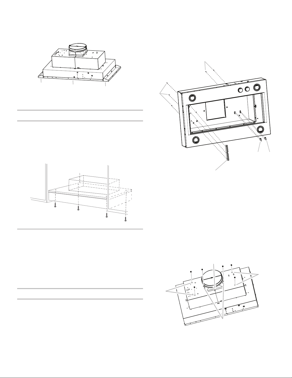
NOTE: For 42" (106.7 cm) and 48" (121.9 cm) wide cabinet
A
A
A
openings, a spacer kit is required. The kit must be assembled to
the range hood prior to mounting the hood to the cabinet.
See “Accessories” in the “Assistance or Service” section to order.
The assembly instructions come with the spacer kits.
3. Install motor spring clip using two 4.2 x 8 mm screws. Screw
spring clip to the inside top or back (alternate location on
some models) of the hood liner at the proper location for the
selected motor system. Slide the mounting tab of the spring
clip through the slot in the panel and secure with the screws.
Use the inside set of mounting holes for the single motor
system. Use the outside set of mounting holes for the dual
motor system.
B
A
A. 42" (106.7 cm) or 48" (121.9 cm)
spacer kit
B. Range Hood
B
A
Install Range Hood Liner
The hood liner attaches to the hood support using four mounting
screws and washers.
NOTE: Hood support must be capable of supporting 75 lb
(34 kg).
1. Using 2 or more people, lift the hood liner into place.
2. Install the hood liner using four 5 x 45 mm screws to the hood
support and tighten securely.
Install Hood Liner Internal Blower
Motor
NOTE: Your hood liner requires you to purchase either an internal
type or an in-line (external type) blower motor system. See
“Blower Motor System” in the “Accessories” section.
The internal blower system can be mounted for top venting or
rear venting. For top venting, the mounting bracket and spring
clip that come with the blower system will mount to the top panel
of the hood liner. For rear venting, the mounting bracket and
spring clip that come with the blower system will mount to the
rear panel of the hood liner.
A
D
C
A. 4.2 x 8 mm screws (3) for motor support bracket
B. 4.2 x 8 mm screws (2) for motor spring clip
C. Motor support bracket
D. Motor spring clip (single motor assembly location)
E. Motor spring clip (dual motor assembly location)
4. Install the 6 mm nuts to the outside top or outside back
(alternate location on some models) of the hood liner at the
proper location for the selected motor system.
■ Two 6 mm nuts are required for the single motor system. Clip
nuts into the small square notches located at the left and right
end of the square vent opening.
■ Five 6 mm nuts are required for the dual motor system. Clip
nuts into the small square notches, one located in the front of
the square vent opening and the other four located at the left
and right ends of the square vent opening.
E
Prepare the Internal Blower System
IMPORTANT: Perform steps 1-4 before mounting the hood liner.
1. Remove grease lters from hood liner. See the “Range Hood
Care” section.
2. Install the motor support bracket using three 4.2 x 8 mm
screws. Screw bracket to the inside top or back (alternate
location on some models), toward the left side of the hood
liner.
8
B
A. Clip nut (6 mm) locations for dual motor assembly (quantity 5)
B. Clip nut (6 mm) locations for single motor assembly (quantity 2)
5. Mount hood liner. See the “Install Range Hood Liner” section.
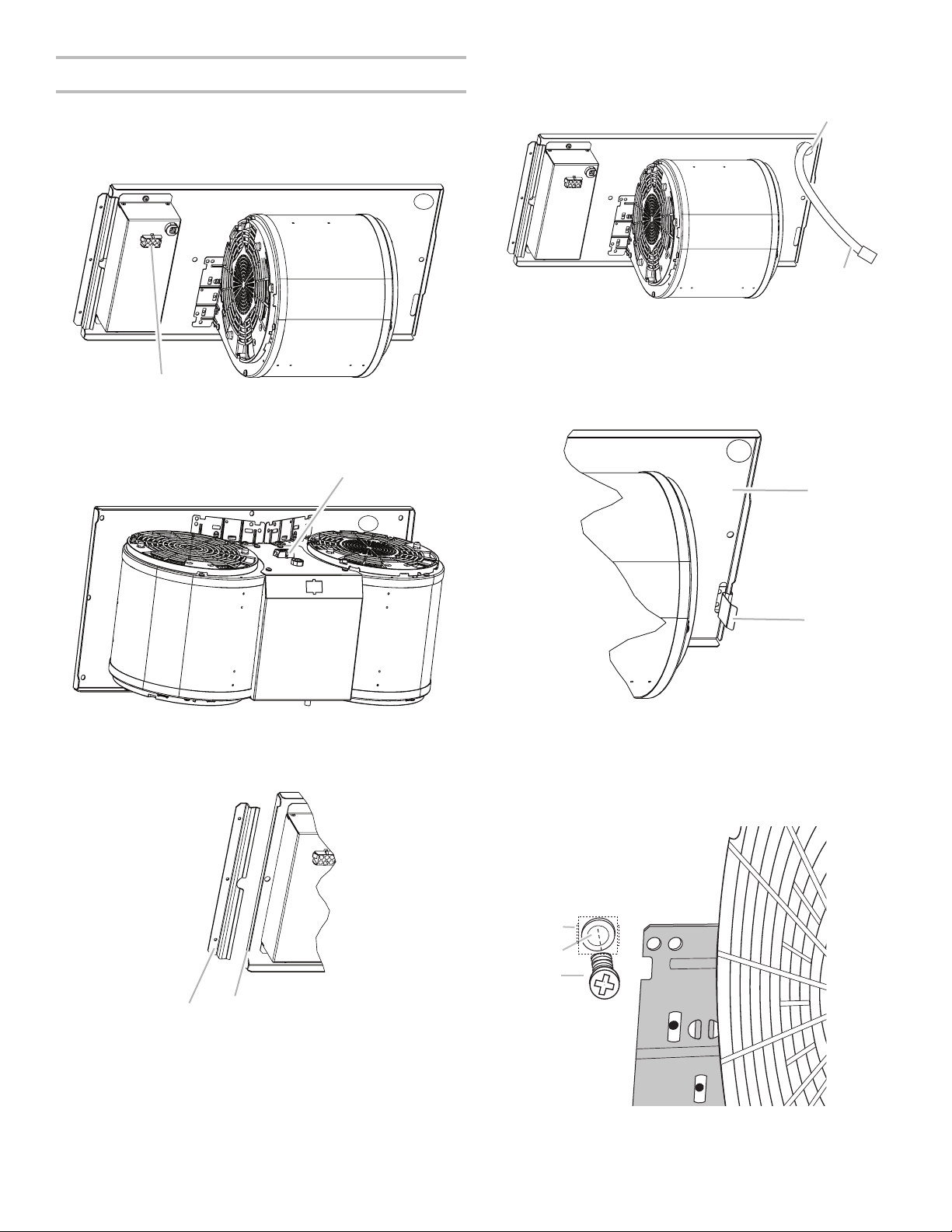
Install Hood Liner Internal Blower Motor
A
A
B
1. Install the hood liner blower motor assembly inside the hood
liner canopy with the wiring connection to the left for the
single motor system and to the front or top for the dual motor
system.
Single Blower Motor Assembly
A
A. Wiring connection
Dual Blower Motor Assembly
3. Run the power supply wires and connector from the range
hood through the hole in the right end of the motor mounting
plate.
A
B
A. Motor mounting plate hole
B. Power supply wires and connector
4. Push the right end of the motor mounting plate up and snap it
into the spring tab.
NOTE: The spring tab should be outside the slot in the mounting
plate.
A. Wiring connection
2. Slide the left mounting plate ange under the motor mounting
bracket.
BA
A. Motor mounting bracket
B. Mounting plate left flange
A. Motor mounting plate
B. Spring clip
5. Align mounting holes in motor mounting plate with motor
mounting clip nuts and install 6 x 16 mm screws and 6.4 mm
lock washers (quantity 2 for single motor; quantity 5 for dual
motor).
C
B
A
A. Screw with lock washer
B. Mounting hole in motor mounting plate
C. Clip nut (6 mm)
9
6. Attach power cord connector from the range hood to
D
A
A
A
connector on wiring box.
6. Pull the spring clip to release the blower motor assembly.
Remove the blower motor assembly from the housing and
place it on a covered surface.
A
A
B
A. Wiring box connector
B. Power supply connector from range
hood
7. Go to the “Make Electrical Power Supply Connection to Hood
Liner” section.
Install Hood Liner In-line (External
Type) Blower Motor
NOTE: Your hood liner requires you to purchase either an internal
type or an in-line (external type) blower motor system. See
“Blower Motor System” in the “Accessories” section.
Prepare for Mounting the In-line Blower System
The in-line blower system must be fastened to a secure
structure of the roof, ceiling, wall, oor, or new or existing frame
construction. The 4 holes on either the inlet (bottom) side or the
outlet (top) side of the blower must be used to mount the in-line
blower system to the structure.
NOTE: The mounting hole locations must span the studs.
Additional stud framing may be required. Plywood may be used
to span open areas between ceiling joists or roof rafters to aid
installation. This structure must be strong enough to support the
weight of the in-line blower system (50 lb [22.6 kg] min).
Prepare the In-line Blower System
WARNING
B
C
A. Front cover
B. Blower mounting screws
C. Spring clip
D. Bottom housing mounting holes
E. Motor electrical plug
Install In-line Blower System
NOTE: The blower motor housing can be mounted using 4 holes
from either the inlet side or the outlet side of the blower.
Outlet Side
A
A. Mounting holes
Inlet Side
Excessive Weight Hazard
Use two or more people to move and install in-line
blower motor system.
Failure to do so can result in back or other injury.
1. Using 2 or more people, move the in-line blower motor
system to the mounting location.
2. Remove the 10 screws from the front cover of the in-line
blower motor housing and set them aside.
3. Remove the front cover of the in-line blower motor housing
and set it aside.
NOTE: To make the blower motor housing easier to mount,
the blower motor assembly can be removed. If you do not
want to remove the blower motor assembly, proceed to
“Install In-line Blower System” in this section.
4. Disconnect the motor electrical plug from the blower motor
assembly.
5. Remove the screws that secure the blower motor assembly to
the in-line blower housing and set them aside.
1. Position the in-line blower motor housing in its mounting
location and mark the 4 mounting hole locations.
2. Drill 4 mounting pilot holes using a 3/16" (5 mm) drill bit.
3. Attach the in-line blower motor housing to the mounting
location with four 6 x 80 mm mounting screws and washers.
4. If it is removed, reinstall the blower motor assembly and
secure it with the screws previously removed.
5. If it is removed, reattach the motor electrical plug to the
connector on the blower motor assembly.
A
A
10
Complete Preparation
A
B
1. Determine and make all necessary cuts for the vent system.
IMPORTANT: When cutting or drilling into the ceiling or wall,
do not damage electrical wiring or other hidden utilities.
2. Determine the location where the 1/2" (1.3 cm) wiring conduit
will be routed through the ceiling or wall between the in-line
blower and the hood liner.
3. Drill a 1¹⁄4" (3.2 cm) hole at this location.
4. Locate the electrical terminal boxes in the in-line blower
housing and hood liner. Remove the terminal box covers and
set the covers and screws aside.
A. Electrical terminal box
B. Electrical knockout
5. Remove the electrical knockout from the in-line blower
housing and hood liner to prepare for the installation of the
UL listed or CSA approved 1/2" (1.3 cm) wiring conduit and
conduit connector.
6. With the hood liner mounted (see the “Install Hood Liner”
section), run the 1/2" (1.3 cm) wiring conduit between the
in-line blower motor housing and the hood liner. Pull enough
1/2" (1.3 cm) wiring conduit to allow for easy connection to
the terminal boxes in the in-line blower housing and hood
liner.
7. Run the six 18 AWG wires through the 1/2" (1.3 cm) wiring
conduit and conduit connectors and into the terminal
boxes on the in-line blower housing and hood liner. Leave
enough wire length in each terminal box to make the wiring
connections.
8. Install the conduit connectors and conduit to the in-line
blower housing and hood liner electrical terminal boxes.
9. Connect the vent system to the hood liner and in-line blower
system and seal all joints with clamps.
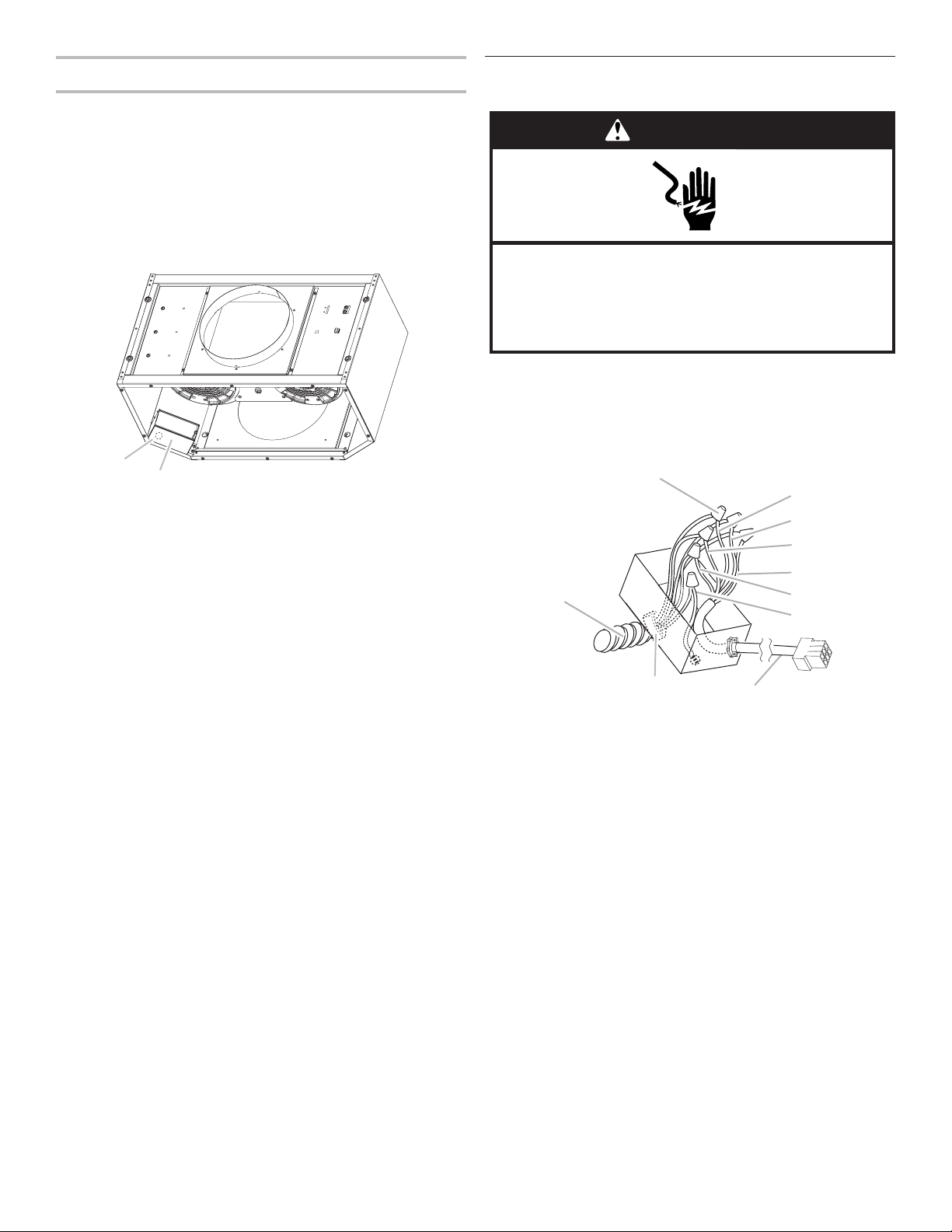
Make Electrical Connections for In-line
Blower Motor System
WARNING
Electrical Shock Hazard
Disconnect power before servicing.
Replace all parts and panels before operating.
Failure to do so can result in death or electrical shock.
Electrical Connection Inside In-line Blower System
1. Disconnect power.
2. Connect the wires from the wiring conduit to the wires from
the motor electrical plug cable inside the in-line blower
housing terminal box.
B
C
D
E
F
A
J
A. UL listed or CSA approved
1/2" (1.3 cm) wiring conduit
B. UL listed wire connectors
C. Black wires
D. White wires
E. Red wires
3. Use UL listed wire connectors and connect the black wires
(C) together.
4. Use UL listed wire connectors and connect the white wires
(D) together.
5. Use UL listed wire connectors and connect the red wires (E)
together.
6. Use UL listed wire connectors and connect the blue wires (F)
together.
7. Use UL listed wire connectors and connect the gray wires (G)
together.
F. Blue wires
G. Gray wires
H. Green (or yellow/green) and
green/yellow wires
I. Motor electrical plug cable
J. UL listed or CSA approved
1/2" (1.3 cm) strain relief
G
H
I
11
 Loading...