

Page 1
JENN-AIR® DETAILED PLANNING DIMENSIONS
Bottom of Cutout
Back of
Cabinet
I
H
G
F
B
A
D
E
F
G
H
D
E
C
Power Cord Location
Power Cord Location
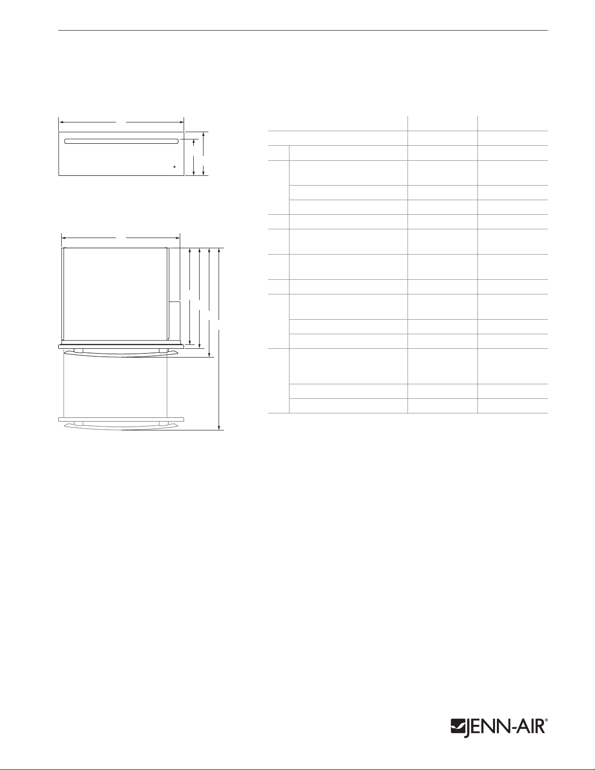
30"/27" WARMING DRAWERS
JWD3030E – 293⁄4" x 101⁄4" x 261⁄4"
JWD3027E – 263⁄4" x 101⁄4" x 261⁄4"
PRODUCT DIMENSIONS
1 of 4
FRONT VIEW
A
MODEL # JWD3030E JWD3027E
in cm in cm
B
C
Overall width (max.) 293⁄4 75.6 263⁄4 67.9
A
Height to top of handle
Pro-Style® Stainless 91⁄8 23.2 — —
B
Euro-Style Stainless 9 23.0 9 23.0
Custom panel (3⁄4"/1.9 cm)
Overall height (max.) 101⁄4 26.1 101⁄4 26.1
C
D
E
F
G
H
Width of recessed warming
D
drawer
Depth of recessed warming
E
drawer
Depth with drawer
F
Depth with handle
Pro-Style® Stainless 267⁄8 68.1 — —
G
Euro-Style Stainless 261⁄4 66.6 261⁄4 66.6
Custom panel (3⁄4"/1.9 cm)
* * * *
281⁄4 71.8 251⁄4 64.1
231⁄8 58.7 231⁄8 58.7
241⁄2 61.4 241⁄2 61.4
* * * *
Depth with drawer fully open
including handle
Pro-Style® Stainless 461⁄8 117.1 — —
H
Euro-Style Stainless 451⁄2 115.6 451⁄2 115.6
Custom panel (3⁄4"/1.9 cm)
* These dimensions to be determined by the custom cabinet maker.
* * * *
TOP VIEW
IMPORTANT: Dimensional specifications are provided for planning purposes only.
Do not make any cutouts based on this information. Refer to the Installation Guide before
selecting cabinetry, verifying electrical/gas connections, making cutouts or beginning installation.
All Jenn-Air® appliances are appropriately UL, CUL or CSA approved. 86 89 Ad Zw1216
Page 2
JENN-AIR® DETAILED PLANNING DIMENSIONS
Power Cord Location
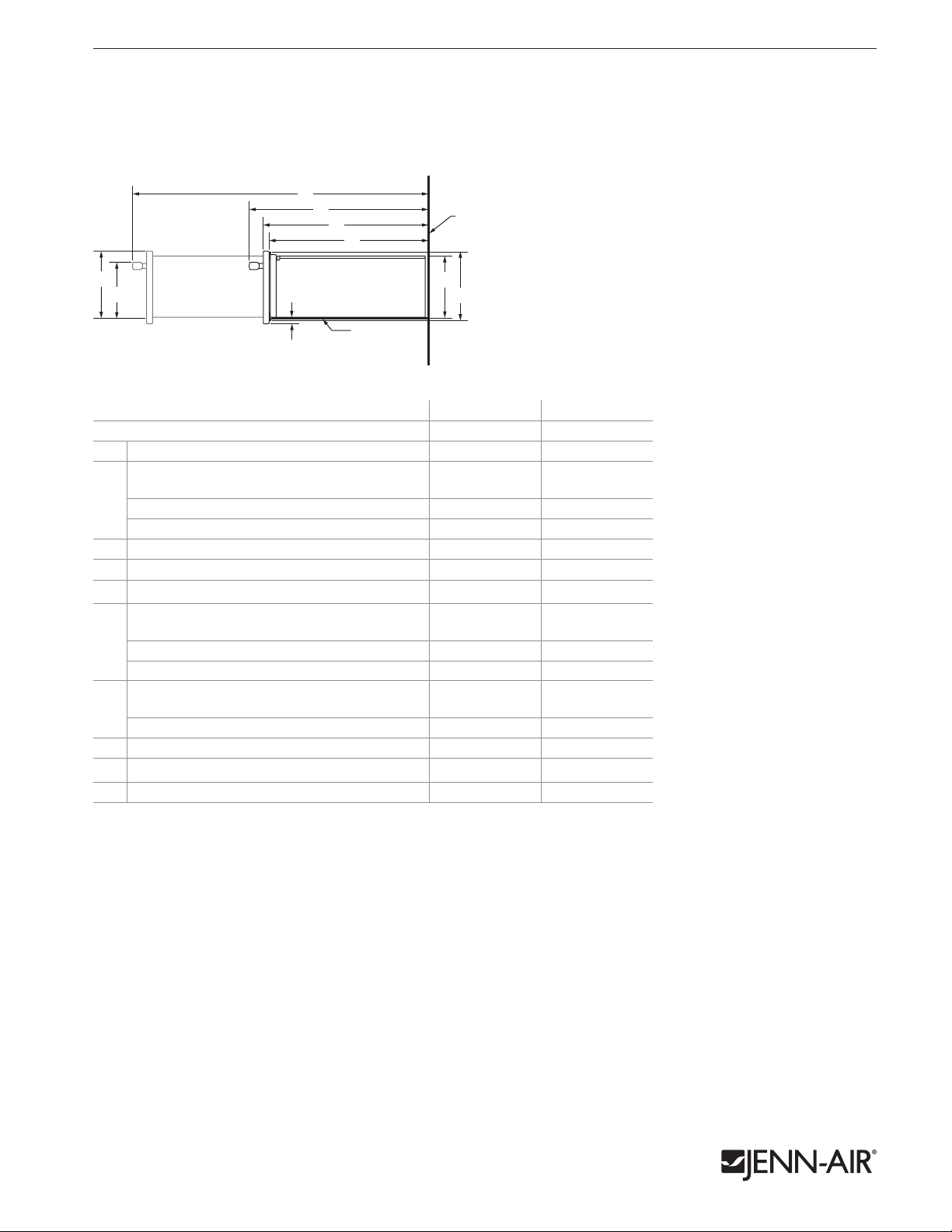
30"/27" WARMING DRAWERS
JWD3030E – 293⁄4" x 101⁄4" x 261⁄4"
JWD3027E – 263⁄4" x 101⁄4" x 261⁄4"
DIMENSIONS AS INSTALLED
F
G
H
I
Back of
Cabinet
2 of 4
A
B
SIDE VIEW
C
Bottom of Cutout
D
E
MODEL # JWD3030E JWD3027E
in cm in cm
Height to top of drawer (max.) 101⁄4 26.1 101⁄4 26.1
A
Height to top of handle
Pro-Style® Stainless
B
Euro-Style Stainless 81⁄2 21.5 81⁄2 21.5
Custom panel (3⁄4"/1.9 cm)
Height of drawer extending below cutout
C
Height of recessed warming drawer 9 23.0 9 23.0
D
Height of warming drawer flange 97⁄8 25.0 97⁄8 25.0
E
Depth with drawer fully open including handle
Pro-Style® Stainless
F
Euro-Style Stainless 451⁄2 115.6 451⁄2 115.6
Custom panel (3⁄4"/1.9 cm)
Depth with handle
Pro-Style® Stainless
G
Euro-Style Stainless 261⁄4 66.6 261⁄4 66.6
Custom panel (3⁄4"/1.9 cm)
Depth with drawer 24 61.0 24 61.0
H
Depth of recessed warming drawer 231⁄8 58.8 231⁄8 58.8
I
* These dimensions to be determined by the custom cabinet maker.
85⁄8
21.9
—
* * * *
5
⁄8 1.6
461⁄8 117.1
5
⁄8 1.6
—
* * * *
267⁄8 68.1
—
* * * *
—
—
—
IMPORTANT: Dimensional specifications are provided for planning purposes only.
Do not make any cutouts based on this information. Refer to the Installation Guide before
selecting cabinetry, verifying electrical/gas connections, making cutouts or beginning installation.
All Jenn-Air® appliances are appropriately UL, CUL or CSA approved. 86 89 Ad Zw1216
Page 3

JENN-AIR® DETAILED PLANNING DIMENSIONS
A
Back of Cabinet
F
30"/27" WARMING DRAWERS
JWD3030E – 293⁄4" x 101⁄4" x 261⁄4"
JWD3027E – 263⁄4" x 101⁄4" x 261⁄4"
OPENING/CLEARANCE DIMENSIONS
MODEL # JWD3030E JWD3027E
Width of cabinet (min.) 30 76.2 27 68.6
A
Width of cutout 281⁄2 72.4 251⁄2 64.8
B
Height between cutouts (min.) 21⁄2 6.4 21⁄2 6.4
C
Height of cutout 91⁄8 23.2 91⁄8 23.2
D
Bottom of cutout to floor (recommended) 41⁄4 10.8 41⁄4 10.8
E
Bottom of cutout to floor (min.) 1 2.5 1 2.5
Depth of cutout (min.) 24 61.0 24 61.0
F
e
Recommended outlet location
ELECTRICAL REQUIREMENTS
120 volt, 60 Hz, AC only, 15-amp fused, electrical circuit is required. A dedicated circuit
is recommended.
If the outlet is on the rear wall behind the warming drawer, it must be recessed and located in
the upper right-hand corner. If outlet is located in an adjacent cabinet, drill a 13⁄8" (3.5 cm)
minimum diameter hole in the side wall or support surface to access the power supply cord.
LOCATION REQUIREMENTS
C
e
B
D
e
D
Support surface must be solid, level and flush with the bottom of the cabinet cutout. The
warming drawer must be leveled before completing installation.
C
3 of 4
in cm in cm
FRONT VIEW
SIDE VIEW
Power Cord Location
BACK VIEW
E
Back of Cabinet
F
IMPORTANT: Dimensional specifications are provided for planning purposes only.
Do not make any cutouts based on this information. Refer to the Installation Guide before
selecting cabinetry, verifying electrical/gas connections, making cutouts or beginning installation.
All Jenn-Air® appliances are appropriately UL, CUL or CSA approved. 86 89 Ad Zw1216
Page 4

JENN-AIR® DETAILED PLANNING DIMENSIONS
Back of Cabinet
G
Back of Cabinet
G
Back of Cabinet
30"/27" WARMING DRAWERS – FLUSH INSTALLATION
JWD3030E – 293⁄4" x 101⁄4" x 241⁄2" (depth without handle)
JWD3027E – 263⁄4" x 101⁄4" x 241⁄2" (depth without handle)
4 of 4
OPENING/CLEARANCE DIMENSIONS
A
B
1" (2.5 cm)
D
7
Platform*
/8" (2.2 cm)
Side Cleats*
e
C
E
F
MODEL # JWD3030E JWD3027E
in cm in cm
Width of flush inset cutout (min.) 301⁄4 76.8 271⁄4 69.2
A
Width of opening (min.) 281⁄4 71.8 251⁄4 64.1
B
Height between cutouts (min.) 21⁄2 6.4 21⁄2 6.4
C
Height of opening (min.) 91⁄8 23.2 91⁄8 23.2
D
Height of flush inset cutout (min.) 103⁄4 27.3 103⁄4 27.3
E
Bottom of cutout to floor (recommended) 81⁄4 21.0 81⁄4 21.0
F
Bottom of cutout to floor (min.) 5 12.7 5 12.7
Depth of cutout (min.) 25 63.5 25 63.5
G
e
Recommended outlet location
ELECTRICAL REQUIREMENTS
120 volt, 60 Hz, AC only, 15-amp fused, electrical circuit is required. A dedicated circuit
is recommended.
If the outlet is on the rear wall behind the warming drawer, it must be recessed and located in
the upper right-hand corner. If outlet is located in an adjacent cabinet, drill a 13⁄8" (3.5 cm)
minimum diameter hole in the side wall or support surface to access the power supply cord.
LOCATION REQUIREMENTS
Support surface must be solid, level and flush with the bottom of the cabinet cutout.
The warming drawer must be leveled before completing installation.
FLUSH INSTALLATION REQUIREMENTS
A 25" (63.5 cm) minimum cutout depth is required.
These dimensions will result in a 1⁄4" (0.6 cm) reveal on all sides of the warming drawer.
The front face of the cleats and platforms will be visible and should be treated as a finished surface.
FRONT VIEW
G
SIDE VIEW
TOP VIEW
Power Cord Location
* Cleats and platform must be recessed 15⁄8" (4.1 cm)
from the front of the cabinet.
BACK VIEW
IMPORTANT: Dimensional specifications are provided for planning purposes only.
Do not make any cutouts based on this information. Refer to the Installation Guide before
selecting cabinetry, verifying electrical/gas connections, making cutouts or beginning installation.
All Jenn-Air® appliances are appropriately UL, CUL or CSA approved. 86 89 Ad Zw1216
Side Cleat*
15/8" (4.1 cm)
Side Cleat*
G
 Loading...