

Jenn-Air JVR0436H Installation Instructions And Use & Care Manual

JENNAIR® 30" (76.2 CM) AND 36" (91.4 CM)
IMPOR
FOR RESIDENTIAL USE ONL
IMPOR
POUR UTILISA
.
WALL-MOUNT CANOPY RANGE HOOD
HOTTE D’EXTRACTION À MONTAGE MURAL DE
30PO (76,2CM) ET 36PO (91,4CM) JENNAIR
®
Installation Instructions and Use & Care Guide
For questions about features, operation/performance, parts, accessories, or service in the U.S.A., call:
1-800-JENNAIR (1-800-536-6247) or visit our website at www.jennair.com.
In Canada, call: 1-800-JENNAIR (1-800-536-6247), or visit our website at www.jennair.ca.
Instructions d’installation et Guide d’utilisation et d’entretien
Pour des questions à propos des caractéristiques, du fonctionnement/rendement, des pièces,
1800JENNAIR (1800536-6247) ou visiter notre site Web au www.jennair.com.
Au Canada, composer le: 1800JENNAIR (1800536-6247) ou visiter notre site Web au www.jennair.ca.
Table of Contents/Table des matières ..................................... 2
TANT: READ AND SAVE THESE INSTRUCTIONS.
TANT : LIRE ET CONSERVER CES INSTRUCTIONS.
TION RÉSIDENTIELLE UNIQUEMENT
LIB0126461/W11160327B
15-May-2018 14:29:52 EDT | RELEASED
des accessoires ou du dépannage, composer le :
Y.
In some European factories the letter "W" of the part code mentioned herein will be automatically
replaced by the number "4000" (e.g. "W12345678" becomes "400012345678")

TABLE OF CONTENTS
TABLE DES MATIÈRES
RANGE HOOD SAFETY .................................................................3
INSTALLATION REQUIREMENTS .................................................5
Tools and Parts .............................................................................5
Location Requirements ................................................................6
Electrical Requirements ...............................................................7
INSTALLATION INSTRUCTIONS ...................................................8
Prepare Location ..........................................................................8
RANGE HOOD USE ......................................................................15
Controls ......................................................................................15
RANGE HOOD CARE ...................................................................16
Cleaning .....................................................................................16
WIRING DIAGRAM .......................................................................17
ASSISTANCE OR SERVICE .........................................................18
In the U.S.A. ..............................................................................18
In Canada ...................................................................................18
Accessories ................................................................................18
SÉCURITÉ DE LA HOTTE ............................................................19
EXIGENCES D’INSTALLATION ...................................................21
Outils et pièces ...........................................................................21
Exigences d’emplacement .........................................................22
Spécications électriques ..........................................................23
INSTRUCTIONS D’INSTALLATION .............................................24
Préparation de l’emplacement ...................................................24
UTILISATION DE LA HOTTE .......................................................31
Commandes ...............................................................................31
ENTRETIEN DE LA HOTTE .........................................................32
Nettoyage ...................................................................................32
SCHÉMA DE CÂBLAGE ...............................................................33
ASSISTANCE OU DÉPANNAGE ..................................................34
Aux É.-U. ...................................................................................34
Au Canada ..................................................................................34
Accessoires ................................................................................34
2
15-May-2018 14:29:52 EDT | RELEASED
In some European factories the letter "W" of the part code mentioned herein will be automatically
replaced by the number "4000" (e.g. "W12345678" becomes "400012345678")
RANGE HOOD SAFETY
Your safety and the safety of others are very important.
We have provided many important safety messages in this manual and on your appliance. Always read and obey all safety
messages.
This is the safety alert symbol.
This symbol alerts you to potential hazards that can kill or hurt you and others.
All safety messages will follow the safety alert symbol and either the word “DANGER” or “WARNING.”
These words mean:
You can be killed or seriously injured if you don't immediately
DANGER
WARNING
All safety messages will tell you what the potential hazard is, tell you how to reduce the chance of injury, and tell you what can
happen if the instructions are not followed.
State of California Proposition 65 Warnings:
WARNING: This product contains one or more chemicals known to the State of California to cause cancer.
WARNING: This product contains one or more chemicals known to the State of California to cause birth defects or other
reproductive harm.
follow instructions.
You
can be killed or seriously injured if you don't
instructions.
follow
15-May-2018 14:29:52 EDT | RELEASED
In some European factories the letter "W" of the part code mentioned herein will be automatically
replaced by the number "4000" (e.g. "W12345678" becomes "400012345678")
3
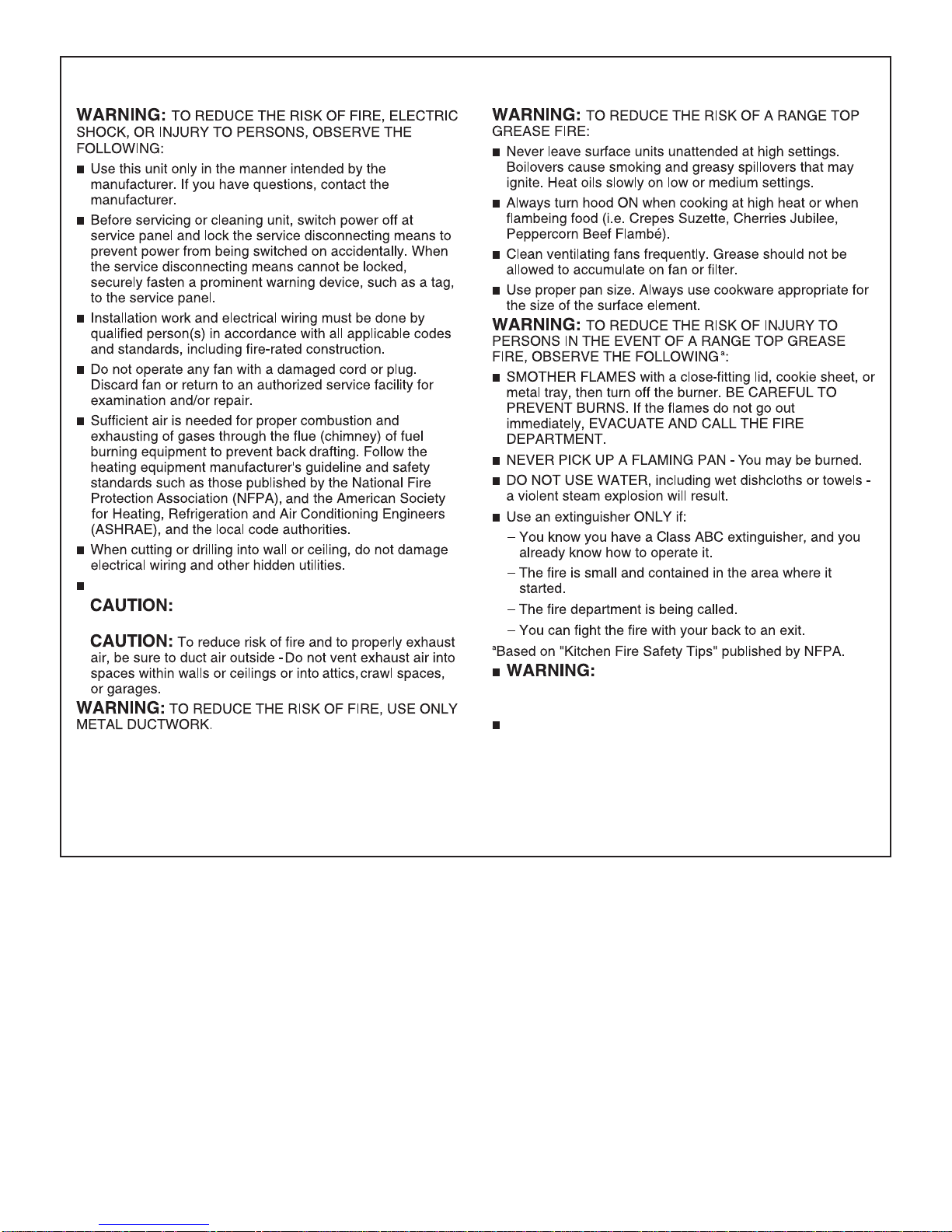
IMPORTANT SAFETY INSTRUCTIONS
Ducted fans must always be vented to the outdoors.
For General Ventilating Use Only. Do Not Use
To Exhaust Hazardous Or Explosive Materials And Vapors.
READ AND SAVE THESE INSTRUCTIONS
To Reduce The Risk Of Fire Or Electric
Shock, Do Not Use This Fan With Any Solid-State Speed
Control Device.
This appliance is not intended for use by people (including
children) whose physical, sensory or mental capacities are
different or impaired or who lack the necessary experience
or knowledge/expertise to do so, unless such persons are
supervised or are trained to operate the appliance by a
person who accepts responsibility for their safety.
4
15-May-2018 14:29:52 EDT | RELEASED
In some European factories the letter "W" of the part code mentioned herein will be automatically
replaced by the number "4000" (e.g. "W12345678" becomes "400012345678")
INSTALLATION REQUIREMENTS
6"
(15.2 cm)
Tools and Parts
Gather the required tools and parts before starting installation.
Read and follow the instructions provided with any tools
listedhere.
Tools needed:
■ Level
■ Drill with 1
drill bits
■ Pencil
■ Tape measure or ruler
■ Adhesive tape
■ Flat-blade screwdriver
■ Metal snips
■ Phillips screwdriver
■ POZI driver
■ T20
Parts needed:
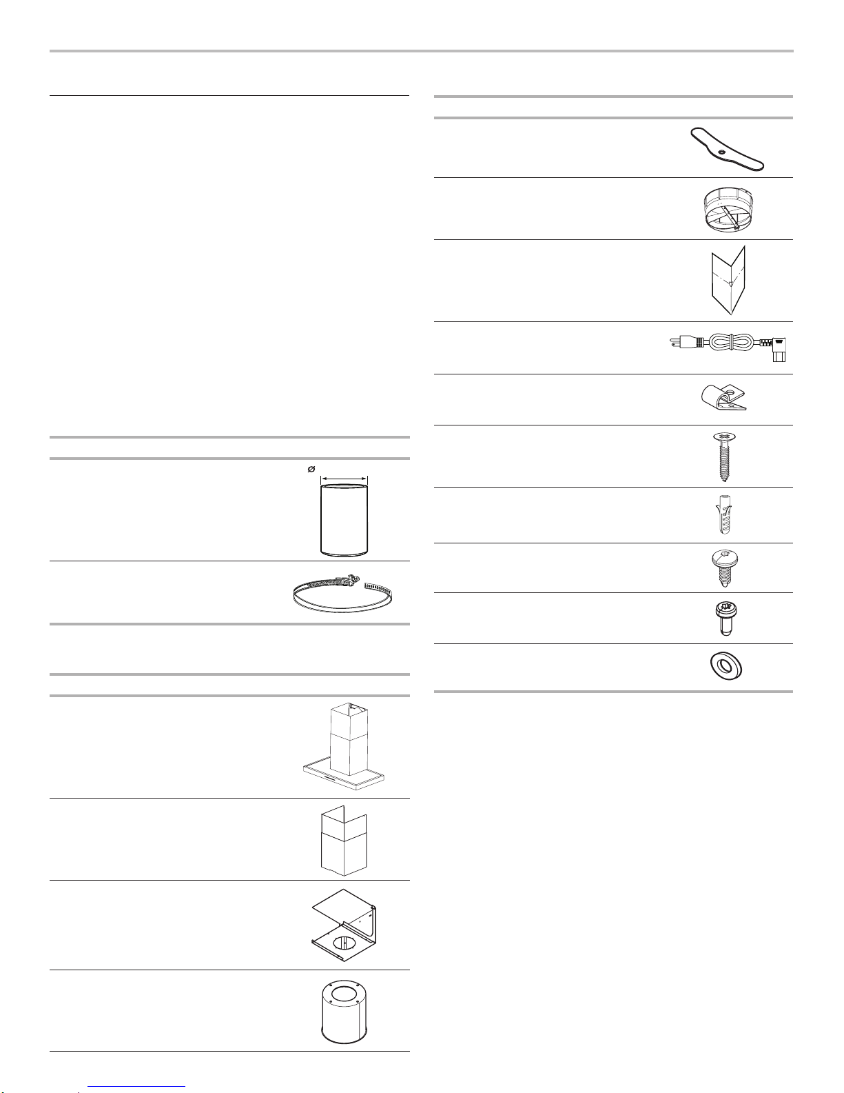
Part Name Qty.
Flexible duct as per
ceiling height;
external diameter
6" (15.2 cm)
1
/4" (3.0 cm), 3/16" (5.0 mm) and 6/19" (8.0 mm)
®
Torx® bit or driver
1
Part Name Qty.
Charcoal lter
3
clamps
Plastic transition 1
Paper template 1
3 prong plug with
1
connector
Wire clamp 1
Ø5 x 45 mm screws 8
Ø8 x 40 mm anchors 8
Steel duct clamps for
2
6" (15.2 cm) ducts
Parts supplied:
Remove parts from packages. Check that all parts are included.
Part Name Qty.
Hood canopy
assembly with
ventilator and lights
installed
Chimney covers 2
Charcoal lter
mounting bracket
1
1
3.5 x 9.5 mm screws 6
2.9 x 6.5 mm pins 2
Flat washers 3
Charcoal lter 1
15-May-2018 14:29:52 EDT | RELEASED
In some European factories the letter "W" of the part code mentioned herein will be automatically
replaced by the number "4000" (e.g. "W12345678" becomes "400012345678")
5
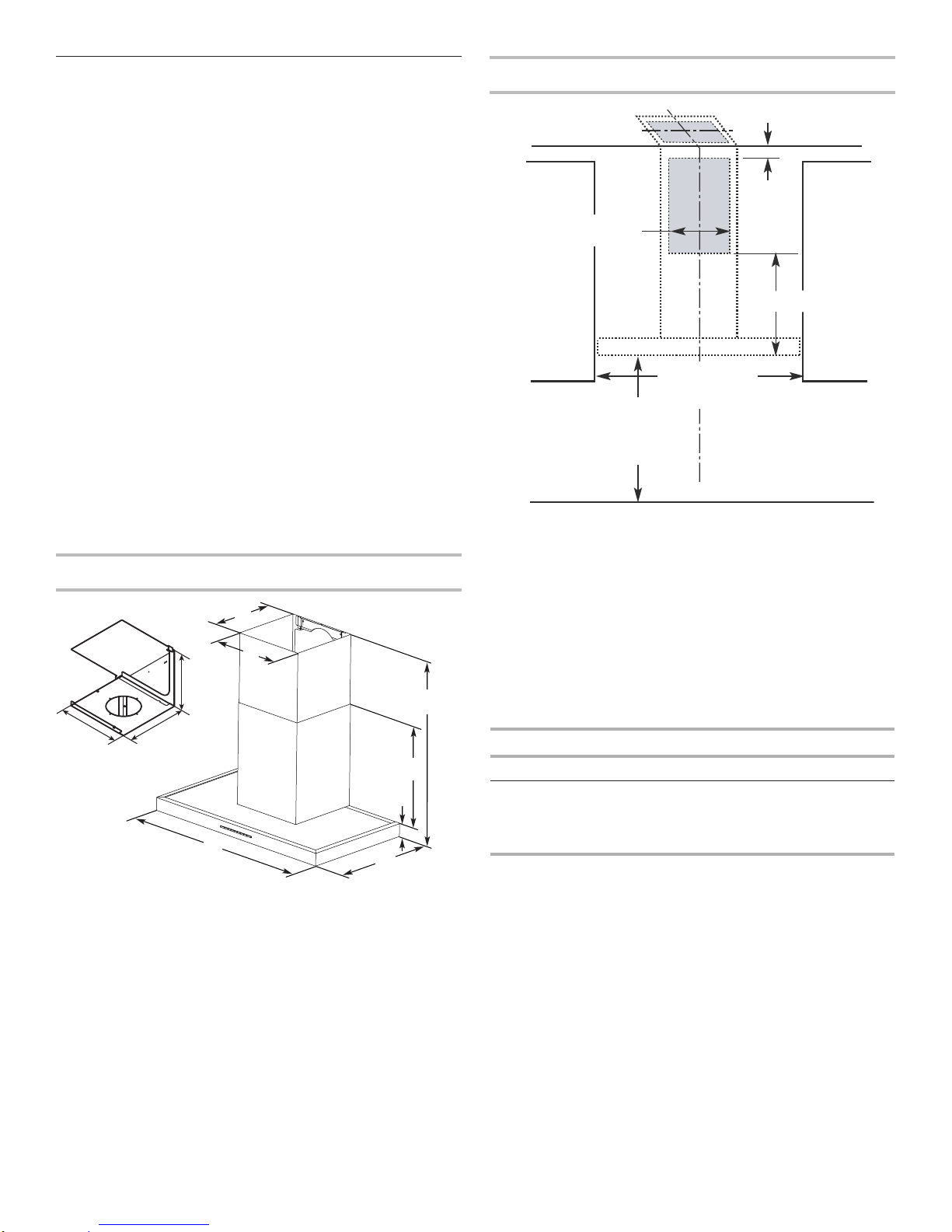
Cooking surface
11
G
Location Requirements
Cabinet Dimensions
IMPORTANT: Observe all governing codes and ordinances.
Have a qualied technician to install the range hood. It is the
installer’s responsibility to comply with installation clearances
specied on the model/serial/rating plate. The model/serial/
rating plate is located behind the left lter on the rear wall of
thevent hood.
Canopy hood location should be away from strong draft
areas,such as windows, doors and strong heating vents.
Cabinet opening dimensions that are shown must be used.
Given dimensions provide minimum clearance.
The canopy hood mounting location must be capable
ofsupporting 100 lbs (45.4 kg).
This range hood is recommended for use with cooktops
withamaximum total rating of 68,000 BTUs or less.
Grounded electrical outlet is required. See the “Electrical
Requirements” section.
All openings in ceiling and wall where canopy hood will be
installed must be sealed.
For Mobile Home Installations:
The installation of this range hood must conform to the
Manufactured Home Construction Safety Standards, Title 24
CFR, Part 328 (formerly the Federal Standard for Mobile Home
Construction and Safety, Title 24, HUD, Part 280) or when such
standard is not applicable, the standard for Manufactured Home
Installation 1982 (Manufactured Home Sites, Communities
and Setups) ANSI A225.1/NFPA 501A, or latest edition, or
withlocalcodes.
Product Dimensions
A
B
H
J
A. 125/8" (32.1 cm)
B. 1213/16" (32.5 cm)
C. For 30" (76.2 cm) models,
D. For 30" (76.2 cm) models,
I
C
2915/16" (76.0 cm)
For 36" (91.4 cm) models,
3515/16" (91.3 cm)
1715/16" (45.6 cm)
For 36" (91.4 cm) models,
1715/16" (45.6 cm)
F
E
D
E. 23/8" (6.0 cm)
F. 24" (61.0 cm)
G. 385/8" (98.1 cm) min.
491/8" (124.8 cm) max.
H. 115/8" (29.5 cm)
I. 12" (30.5 cm)
J. 123/8" (31.4 cm)
13
11 / " (30.0 cm)
16
13
/ " (30.0 cm) max.
16
11
19 / " (50.0 cm)
16
Side
cabinet
30" (76.2 cm)
36" (91.4 cm)
“X”
bottom of
canopy
to cooking
surface
or
Centerline
Side
cabinet
*For non-vented (recirculating) installations
IMPORTANT:
Minimum distance “X”: 24" (61.0 cm) from electric
cookingsurface.
Minimum distance “X”: 30" (76.2 cm) from gas
cookingsurface.
Suggested maximum distance “X”: 36" (91.4 cm)
NOTE: For best performance of the Auto Sense feature, the
range hood should be installed at 24" (61.0 cm) from an electric
cooking surface and 30" (76.2 cm) from a gas cooking surface.
The chimneys can be adjusted for different ceiling heights.
Seethe following chart.
Installation
Min. ceiling height Max. ceiling height
Electric cooking
8' 25/8" (2.50 m) 10' 4" (3.24 m)
surface
Gas cooking
8' 65/8" (2.61 m) 10' 4" (3.24 m)
surface
*NOTE: The range hood chimneys are adjustable and designed
to meet varying ceiling or soft heights depending on the
distance “X” between the bottom of the range hood and the
cooking surface.
6
15-May-2018 14:29:52 EDT | RELEASED
In some European factories the letter "W" of the part code mentioned herein will be automatically
replaced by the number "4000" (e.g. "W12345678" becomes "400012345678")
30"
(76.2 cm)
Electrical Requirements
Observe all governing codes and ordinances.
Ensure that the electrical installation is adequate and in
conformance with National Electrical Code, ANSI/NFPA 70
(latest edition), or CSA Standards C22.1-94, Canadian Electrical
Code, Part 1 and C22.2 No. 0-M91 (latest edition) and all local
codes and ordinances.
If codes permit and a separate ground wire is used, it is
recommended that a qualied electrician determine that the
ground path is adequate.
A copy of the above code standards can be obtained from:
National Fire Protection Association
1 Batterymarch Park
Quincy, MA 02169-7471
CSA International
8501 East Pleasant Valley Road
Cleveland, OH 44131-5575
■ A 120 V, 60 Hz, AC only, 15 A, fused electrical circuit
isrequired.
For 3 Prong Grounded Power Cord:
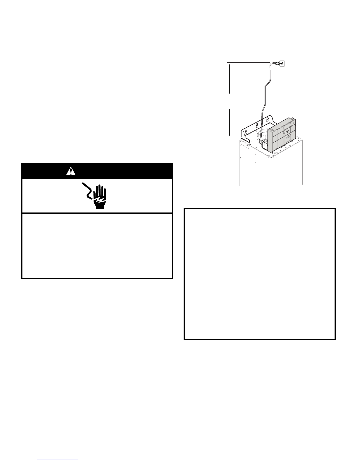
WARNING
■ The grounded 3 prong outlet is to be located above the
range hood at a maximum distance of 30" (76.2 cm) from
where the power cord exits the hood. See illustration.
Electrical Shock Hazard
Plug into a grounded 3 prong outlet.
Do not remove ground prong.
Do not use an adapter.
Do not use an extension cord.
Failure to follow these instructions can result in death,
fire, or electrical shock.
■ This range hood is equipped with a power supply cord
having a 3 prong grounding plug.
■ To minimize possible shock hazard, the cord must be
plugged into a mating, 3 prong, grounding-type outlet,
grounded in accordance with local codes and ordinances.
Ifa mating outlet is not available, it is the responsibility of
thecustomer to have the properly grounded outlet installed
by a qualied electrician.
GROUNDING INSTRUCTIONS
■
For a grounded, cord-connected range hood:
This range hood must be grounded. In the event of an
electrical short circuit, grounding reduces the risk of electric
shock by providing an escape wire for the electric current.
This range hood is equipped with a cord having a grounding
wire with a grounding plug. The plug must be plugged into
an outlet that is properly installed and grounded.
WARNING: Improper grounding can result in a risk of
electric shock.
Consult a qualified electrician if the grounding instructions
are not completely understood, or if doubt exists as to
whether the range hood is properly grounded.
Do not use an extension cord. If the power supply cord is too
short, have a qualified electrician install an outlet near the
range hood.
SAVE THESE INSTRUCTIONS
15-May-2018 14:29:52 EDT | RELEASED
In some European factories the letter "W" of the part code mentioned herein will be automatically
replaced by the number "4000" (e.g. "W12345678" becomes "400012345678")
7
INSTALLATION INSTRUCTIONS
Min 24" (61.0 cm) for Electric
Min 30" (76.2 cm) for Gas
Max 36" (91.4 cm)
18¹/₈" (46.0 cm)
⁵/₁₆" (8 mm)
1
¹
/
₅"
(5 mm)
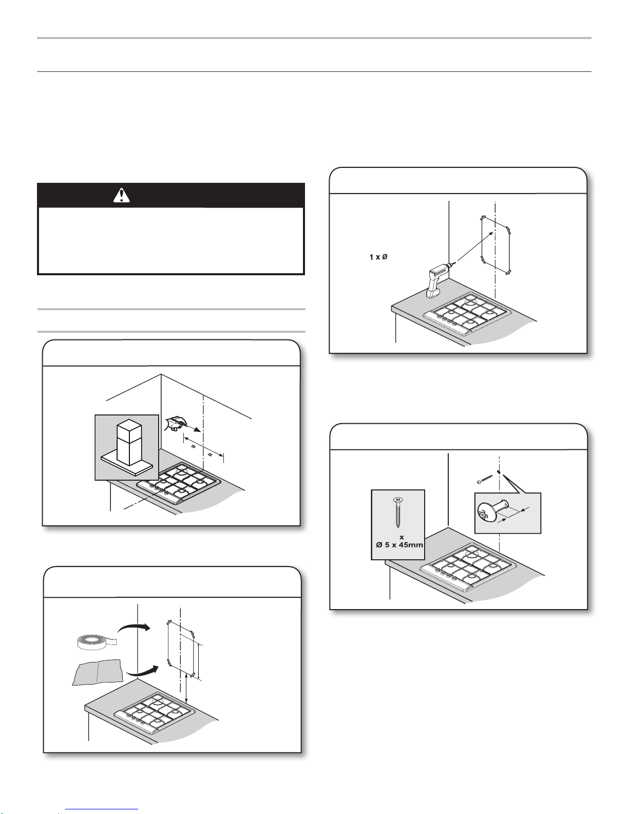
Prepare Location
■ Before making cutouts, make sure there is proper clearance
within the ceiling or wall for exhaust vent.
■ Check your ceiling height and the hood height maximum
before you select your hood.
1. Disconnect power.
2. Select a at surface for assembling the range hood.
Placecovering over that surface.
WARNING
Excessive Weight Hazard
Use two or more people to move and install
range hood.
Failure to do so can result in back or other injury.
3. Using 2 or more people, lift range hood onto
coveredsurface.
Canopy Installation Preparation
1. Mark centerline on wall
■ Tape the template sheet so the lower edge of the sheet
representing the bottom of the hood is at a mounting height
between a minimum of 24" (61.0 cm) for an electric cooking
surface, a minimum of 30" (76.2 cm) for a gas cooking
surface, and a suggested maximum of 36" (91.4 cm) for both
gas and electric cooking surfaces.
3. Drill pilot holes
■ Drill an 5/16" (8 mm) pilot hole per the hole location on the
template sheet.
■ Ensure the hole aligns with the centerline drawn.
■ Remove the template sheet.
■ Determine and mark the centerline on the wall where the
canopy hood will be installed.
2. Tape template to wall
4. Install mounting screw
■ Install one 8 x 40 mm anchor.
■ Install one 5 x 45 mm screw.
■ Ensure the screw has at least 1/5" (5 mm) gap to the wall
when screwed in for mounting the hood.
8
15-May-2018 14:29:52 EDT | RELEASED
In some European factories the letter "W" of the part code mentioned herein will be automatically
replaced by the number "4000" (e.g. "W12345678" becomes "400012345678")
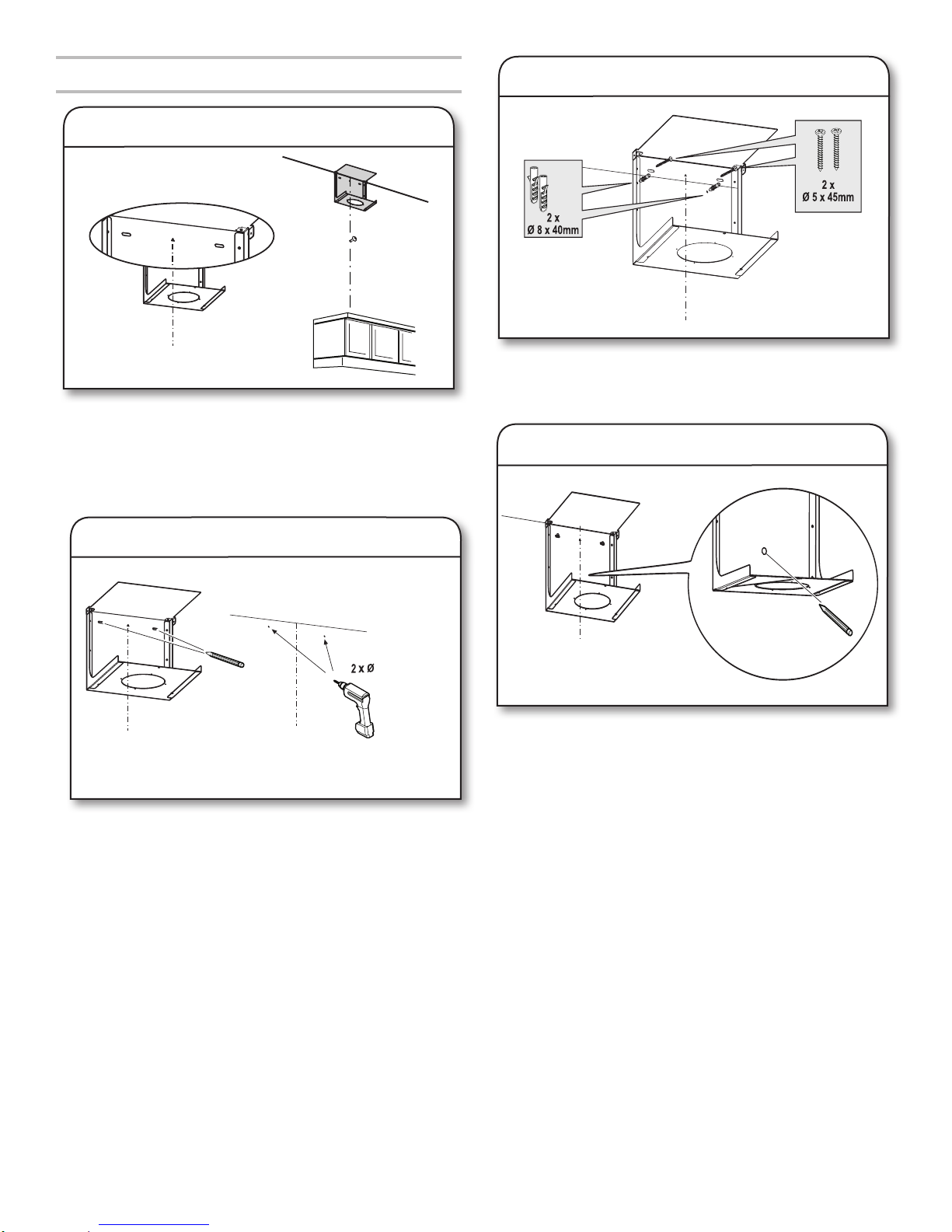
Charcoal Filter Bracket Installation
⁵/₁₆" (8 mm)
1. Align charcoal lter bracket
■ Remove the charcoal lter bracket from the box and place
it at the desired height above the hood canopy bottom (use
provided template for reference).
■ Ensure the center of the bracket is aligned with the center
line marked to conrm the center of the hood aligns with the
center of the lter bracket.
3. Install anchors
■ Install 2 anchors and screw the bracket into place.
■ Do not fully tighten the screws as the bracket will need to be
removed in the next step.
4. Mark center hole
2. Drill pilot holes
■ Mark holes as per center line and drill 2-5/16" (8 mm) holes.
Tip: Use a level tool to ensure the bracket is level before
drilling the holes.
■ Mark the center hole with a pencil.
15-May-2018 14:29:52 EDT | RELEASED
In some European factories the letter "W" of the part code mentioned herein will be automatically
replaced by the number "4000" (e.g. "W12345678" becomes "400012345678")
9
3
120 V, 60 Hz
⁵/₁₆" (8 mm)
5. Remove bracket
■ Remove the screws (not the anchors) in order to remove the
bracket.
Prepare for Installation
1. Verify electrical outlet location
6. Drill center hole
■ Drill an 5/16" (8 mm) hole where the center hole is marked
and insert 1-5/16" (8 mm) anchor.
7. Mount charcoal lter bracket
■ Ensure grounded 3 prong outlet capable of 120 V, 60 Hz is
available before proceeding.
■ Ensure at least 2/5" (1 cm) gap between bottom of the
charcoal lter bracket to top of the grounded 3 prong outlet.
■ Ensure at least 1
the bottom of the grounded 3 prong outlet.
■ Ground 3 prong outlet must be 4/5" (2 cm) shorter in width
than the chimney width.
9
/50" (3 cm) gap between anchor screw and
2. Remove grease lter
■ Place the charcoal lter bracket back into position so that all
the holes are aligned with the anchors.
■ Secure 2 screws on the upper bracket slots and one screw
with a at washer on the lower bracket slot, to secure the
bracket in position.
10
15-May-2018 14:29:52 EDT | RELEASED
■ Remove grease lters before proceeding.
In some European factories the letter "W" of the part code mentioned herein will be automatically
replaced by the number "4000" (e.g. "W12345678" becomes "400012345678")
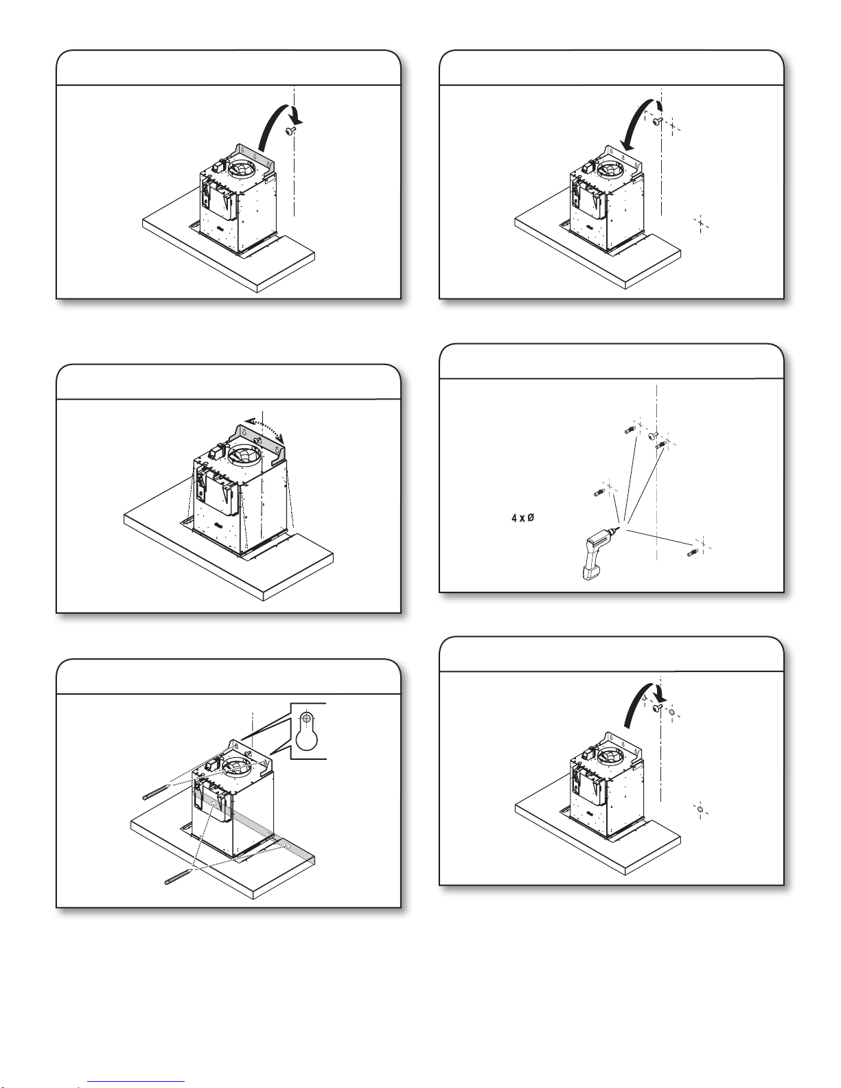
3. Place hood on mounting screw
⁵/₁₆" (8 mm)
6. Remove hood
■ Using 2 or more people, hang the range hood on the
mounting screw through the mounting slot on the back of the
hood.
4. Level hood
■ Use a level to ensure the hood is level before proceeding.
5. Mark mounting hole
■ Using 2 or more people, remove the hood.
7. Drill holes
■ Drill 4-5/16" (8 mm) holes.
8. Mount range hood
■ Once you have the hood aligned properly, use a pencil to
mark 4 holes as shown in the picture.
15-May-2018 14:29:52 EDT | RELEASED
■ Using 2 or more people, hang the range hood on the
mounting screw through the mounting slot on the back of the
hood.
In some European factories the letter "W" of the part code mentioned herein will be automatically
replaced by the number "4000" (e.g. "W12345678" becomes "400012345678")
11
 Loading...