

Jenn-Air JVD0303GS User Manual
JENN-AIR® DETAILED PLANNING DIMENSIONS
21
OFF
A
B
G
21
OFF
A
B
C*
H*
D
G
E
F
I
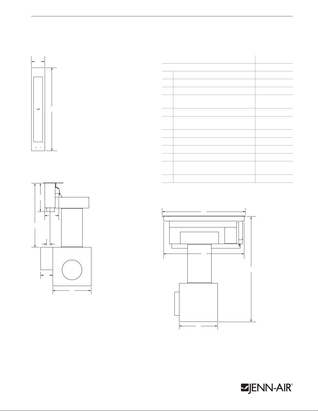
4" MODULAR DOWNDRAFT VENT
JVD0303GS – 37⁄8" x 21"
PRODUCT DIMENSIONS
1 of 2
A
MODEL # JVD0303GS
in cm
Overall width 37⁄8 9.8
A
Overall depth 21 53.3
B
Width of vent module base 47⁄32 10.7
C*
Center of vent module to center of
D
electrical conduit
Height of vent module base 87⁄8 22.5
E
Height from electrical conduit to
F
underside of vent module face
Thickness of vent module face
G
Width of electrical box 35⁄8 9.2
H
Width of blower housing assembly 11 27.9
I
Depth of vent module base 205⁄16 51.6
J
Height from bottom of blower housing
K
assembly to countertop (min.-max.)
Depth of blower housing assembly 11 27.9
L
* Measured from tab to tab. Tabs should not be bent during installation.
31
⁄32 2.5
187⁄8 47.9
1
⁄8 0.3
2951⁄64 75.7
21
OFF
TOP VIEW
B
E
F
FRONT VIEW
C*
B
D
J
K
H*
I
L
SIDE VIEW
IMPORTANT: Dimensional specifications are provided for planning purposes only.
Do not make any cutouts based on this information. Refer to the Installation Guide before
selecting cabinetry, verifying electrical/gas connections, making cutouts or beginning installation.
All Jenn-Air® appliances are appropriately UL, CUL or CSA approved.
8998AdZw917
JENN-AIR® DETAILED PLANNING DIMENSIONS
D* G
E
A
B
B
C
e
F
Side
Cabinet
G
Side
Cabinet
H
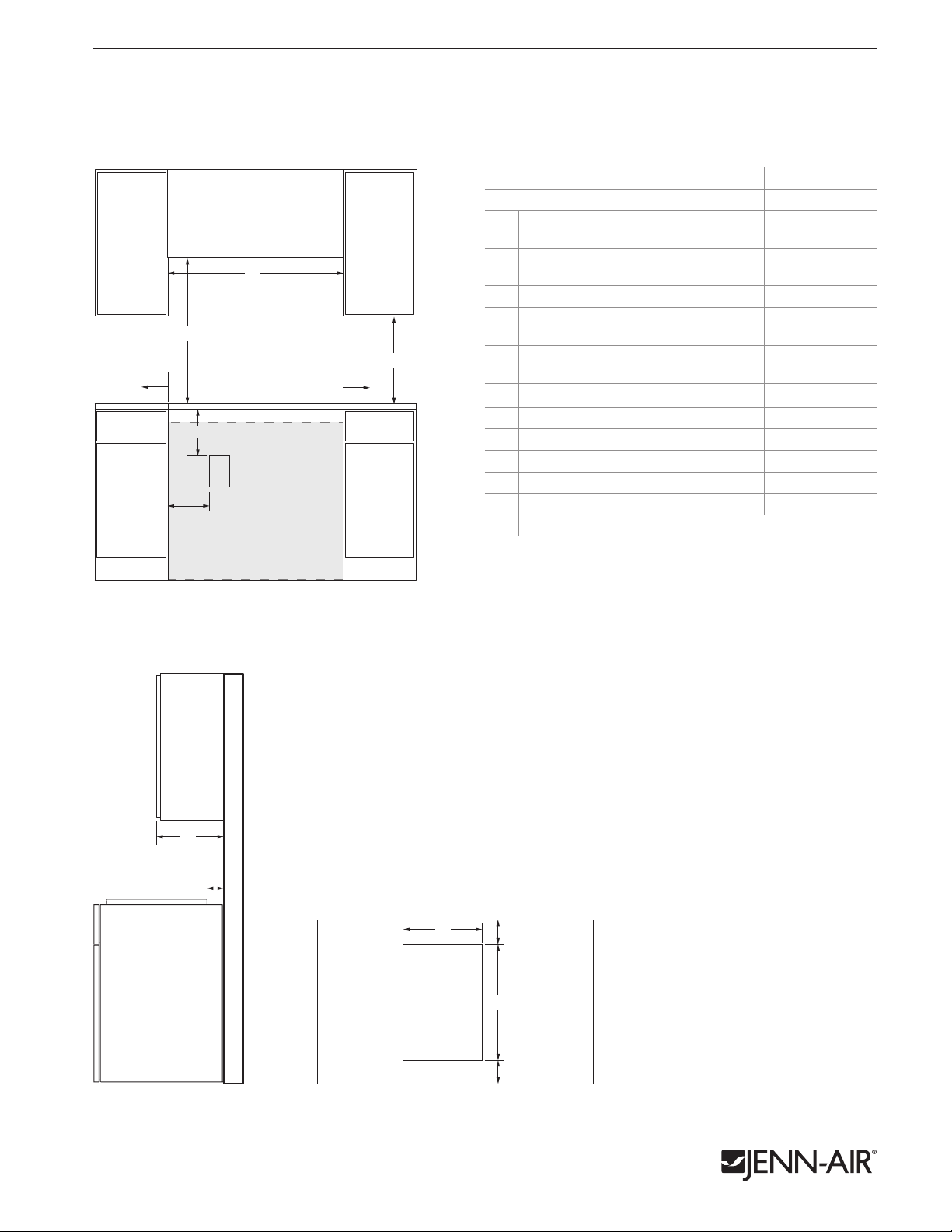
4" MODULAR DOWNDRAFT VENT
JVD0303GS – 37⁄8" x 21"
OPENING/CLEARANCE DIMENSIONS
MODEL # JVD0303GS
Width of combustible area above
A
cooking surface (min.)
Width from vent module to fixed wall or
B
other combustible material (min.)
Width to outer edge of outlet (max.) 6 15. 2
C
Height to bottom of uncovered wood or
D*
metal cabinet above cooking surface (min.)
Height to bottom of uncovered wood or
E
metal cabinet (min.)
Height to top edge of outlet (min.) 10 25.4
F
Depth of upper cabinet 13 33.0
G
Depth from cutout to wall (min.) 25⁄16 5.9
H
Width of cutout with one module 183⁄16 46.2
I
Depth of cutout (recommended) 203⁄8 51.8
J
Depth from cutout to front of countertop 25⁄16 5.9
K
e
Recommended electrical access location
* Dimension can be reduced by 6" (15.2 cm) when bottom of wood or metal
cabinet is covered by not less than 1⁄4" (0.6 cm) flame retardant millboard
covered with not less than No. 28 MSG sheet metal, 0.015" (0.4 mm)
stainless steel, 0.024" (0.6 mm) aluminum or 0.020" (0.5 mm) copper.
If installing a hood or microwave hood combination above the cooktop,
follow the hood or microwave hood combination instructions for
dimensional clearances above the cooking surface.
B
FRONT VIEW
A
D*
E
B
F
e
C
2 of 2
in cm
187⁄8 4 7. 9
6 15. 2
30 76.2
18 45.7
Side
Cabinet
G
ELECTRICAL REQUIREMENTS
A 120 Volt, 60 Hz, AC only 15-amp fused, grounded electrical circuit is
required. A dedicated circuit is required.
A grounded 3-prong outlet should be located in the back of the cabinet.
Do not use an extension cord.
LOCATION REQUIREMENTS
• To ensure cooktop base clearance, cabinet side walls need to be wider
than the cutout.
H
I
H
J
K
TOP VIEWSIDE VIEW
IMPORTANT: Dimensional specifications are provided for planning purposes only.
Do not make any cutouts based on this information. Refer to the Installation Guide before
selecting cabinetry, verifying electrical/gas connections, making cutouts or beginning installation.
All Jenn-Air® appliances are appropriately UL, CUL or CSA approved.
8998AdZw917
 Loading...