

Jenn-Air JVD0303GS Installation Manual
INSTALLATION INSTRUCTIONS FOR
DOWNDRAFT VENT
Table of Contents
COOKTOP SAFETY
INSTALLATION REQUIREMENTS
Tools and Parts
Location Requirements
Electrical Requirements
Venting Requirements
External Venting Dimensional Planning
INSTALLATION INSTRUCTIONS
Mounting Bracket Installation
Install Foam Strips
Recirculation (Non-ducted) Installation
Install Cooktop, Downdraft and Blower Motor Assembly
Complete Installation
WIRE DIAGRAM
........................................................................1
.................................................3
.............................................................................3
................................................................3
...............................................................4
..................................................................8
.......................................9
.................................................11
....................................................11
.....................................................................11
......................................11
.........12
.................................................................13
...........................................................................14
COOKTOP SAFETY
Your safety and the safety of others are very important.
We have provided many important safety messages in this manual and on your appliance. Always read and obey all safety
messages.
This is the safety alert symbol.
This symbol alerts you to potential hazards that can kill or hurt you and others.
All safety messages will follow the safety alert symbol and either the word “DANGER” or “WARNING.”
These words mean:
You can be killed or seriously injured if you don't immediately
DANGER
WARNING
All safety messages will tell you what the potential hazard is, tell you how to reduce the chance of injury, and tell you what can
happen if the instructions are not followed.
IMPORTANT:
Save for local electrical inspector’s use.
W11170792A
follow instructions.
You
can be killed or seriously injured if you don't
instructions.
follow
IMPORTANT SAFETY INSTRUCTIONS
READ AND SAVE THESE INSTRUCTIONS
2
INSTALLATION REQUIREMENTS
C
A
B
Center of Intake
Tools and Parts
Gather the required tools and parts before starting installation.
Read and follow the instructions provided with any tools
listed here.
Tools Needed
■ Tape measure ■ Marker or pencil
■ Phillips screwdriver ■ Pliers
■ Flat-blade screwdriver ■ Jigsaw
■ Level ■ Caulking
■ Drill ■ Aluminum duct tape
Parts Supplied
Check that all parts are included.
■ Blower housing assembly with electronic box and intake
assembly
■ (4) Mounting brackets (front and rear mounting brackets) with
screws
■ Grease lter
■ (2) Blower hold down brackets to secure blower to cabinet
■ Round duct 2-piece telescoping (blower assembly)
■ Foam strip
■ (4) Sheet metal screws to secure transition to downdraft
intake and one transition
Parts Needed
For vented installations:
■ 6” (15.2 cm) round metal ducting
■ Jenn-Air
Jenn-Air
■ (8) Round or pan head wood and sheet metal screws
See the “Assistance or Service” section in your Use and
Care manual to order.
For non-vented installations:
■ Recirculation Kit part number W10807915 (See the
“Assistance or Service” section in your Use and Care
manualto order.)
a. Recirculation duct housing
b. (4) Mounting screws
c. (2) Charcoal lters
d. Recirculation housing cover
e. (2) Mounting screws – cover
f. Duct extension
g. (4) Mounting screws – duct extension
For non-vented installations side recirculation only:
■ 1-6” (15.2 cm) round 90 degree elbow and 1-6” (15.2 cm)
round to 3Z\v” x 10” (8.3 cm x 25.4 cm) transition and
1- 3Z\v” x 10” (8.3 cm x 25.4 cm) elbow.
■ Plywood Pedestal to raise blower mounting. See instruction
detail for non-vented installation.
Check local codes. Check existing electrical supply. See the
“Electrical Requirements” section.
It is recommended that all electrical connections be made by
a licensed, qualied electrical installer.
®
wall cap:
®
6” (15.2 cm) round wall cap with damper
■ Use the countertop opening dimensions that are given
with these Installation Instructions. Given dimensions are
minimum clearances and provide 0" (0 cm) clearance.
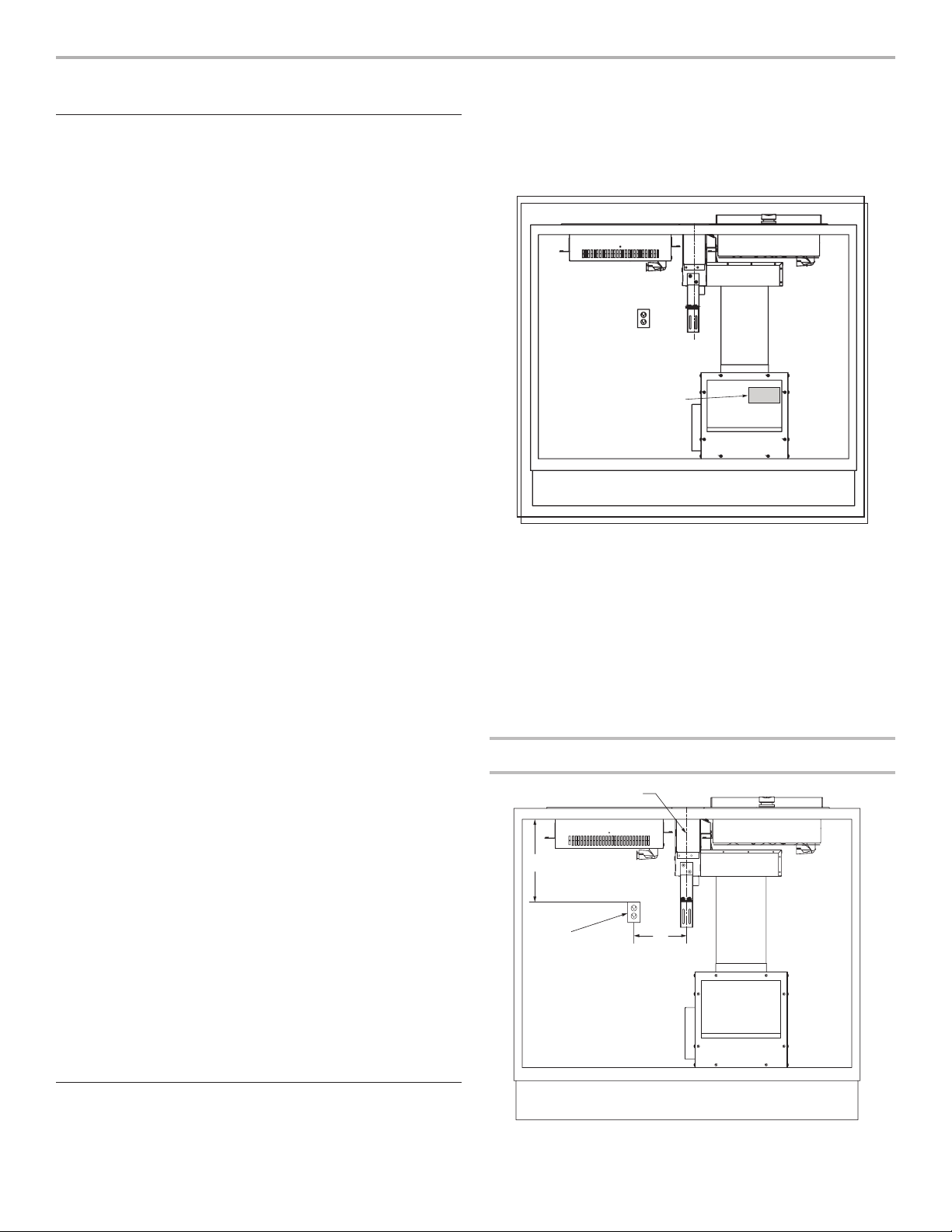
■ The model/serial/rating label is located on the front face of
the electrical junction box cover.
A
A. Model/serial/rating label location
■ Grounded electrical supply is required. See the “Electrical
Requirements” section.
■ If cabinet has drawers, drawers will need to be removed
and drawer fronts installed on front of cabinet.
NOTE: The exhaust system is for outside venting. For
non-vented (recirculating) installation, see “For non-vented
(recirculating) installations only” in the “Connect Vent System”
section. Recirculating Kit part number W10807915 is available
from your dealer or an authorized parts distributor.
IMPORTANT: An undercounter built-in oven cannot be installed
under this product.
Electrical Connection Locations
Location Requirements
IMPORTANT: Observe all governing codes and ordinances.
When installing the downdraft, use the minimum dimensions
given.
A. 3 prong grounding type outlet with correct polarity
B. 12” (30.5 cm) from centerline of downdraft intake
C. 18” (45.7) minimum
3
Electrical Requirements
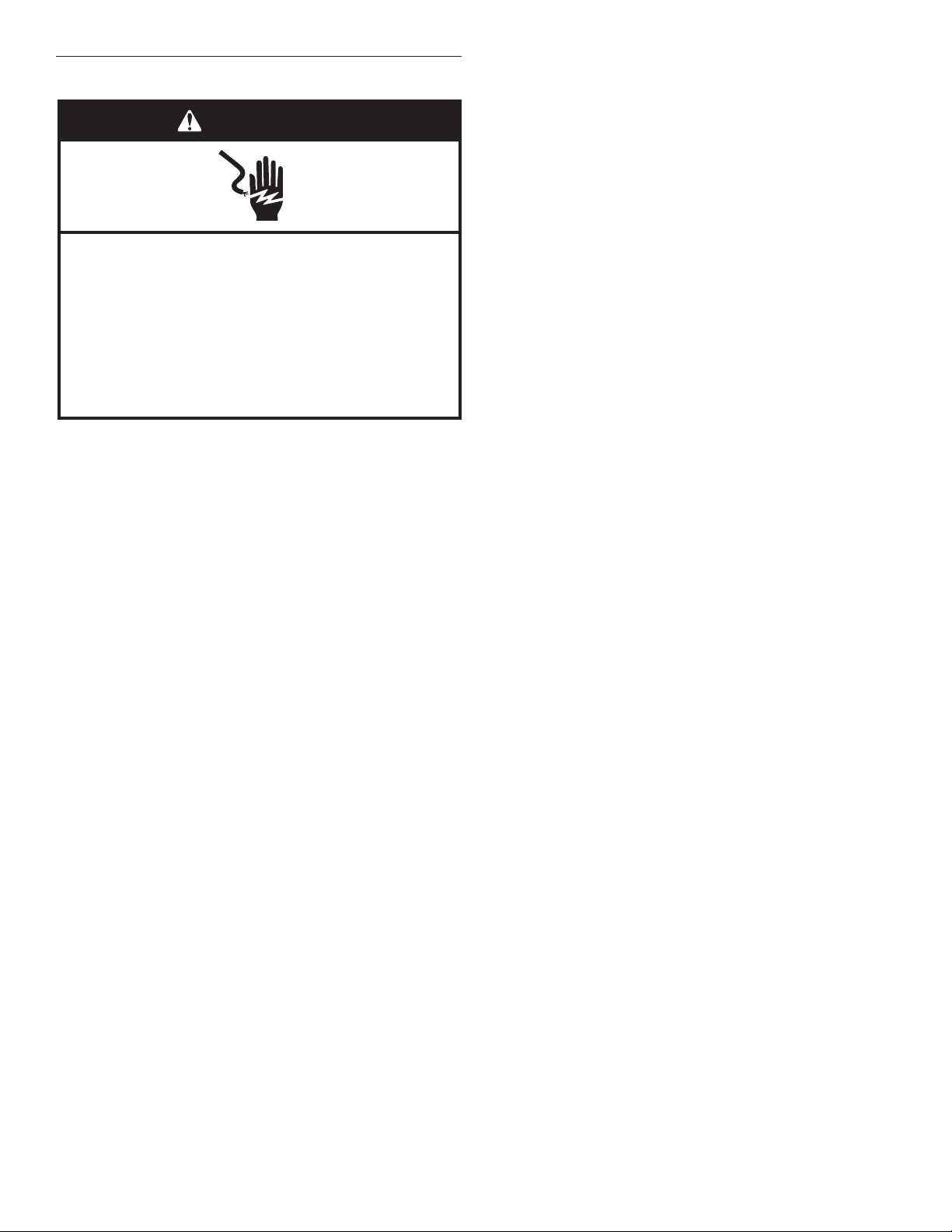
WARNING
Electrical Shock Hazard
Plug into a grounded 3 prong outlet.
Do not remove ground prong.
Do not use an adapter.
Do not use an extension cord.
Failure to follow these instructions can result in death,
fire, or electrical shock.
IMPORTANT: The downdraft vent must be electrically grounded
in accordance with local codes and ordinances, or in the
absence of local codes, with the National Electrical Code, ANSI/
NFPA 70 or Canadian Electrical Code, CSA C22.1.
This downdraft is equipped with an electronic touch pad system
that will not operate if plugged into an outlet that is not properly
polarized.
If codes permit and a separate ground wire is used, it is
recommended that a qualied electrical installer determine that
the ground path is adequate.
A copy of the above code standards can be obtained from:
National Fire Protection Association
1 Batterymarch Park
Quincy, MA 02169-7471
CSA International
8501 East Pleasant Valley Road
Cleveland, OH 44131-5575
■ A 120-volt, 60 Hz., AC-only, 15-amp fused, electrical circuit
is required. A time-delay fuse or circuit breaker is also
recommended. It is recommended that a separate circuit
serving only this downdraft vent be provided.
■ Electronic touch pad systems operate within wide voltage
limits, but proper grounding and polarity are necessary.
Check that the outlet provides 120-volt power and is
correctly grounded and polarized.
■ The wiring diagram is provided with this downdraft vent. See
the “Wiring Diagram” section.
■ Downdraft must have a dedicated electrical receptacle and
power supply.
4
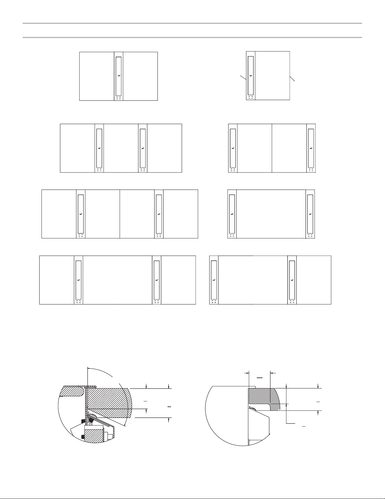
Planning Your Cabinet Cutout
DDDD DD DD
15" (38.1 cm) cooktop
15" (38.1 cm)
15" (38.1 cm)
15" (38.1 cm)
30" (76.2 cm) OR 36" (91.4 cm)30" (76.2 cm) OR 36" (91.4 cm)
[3.1 cm]
[3.18 cm]
Installation Options for Modular Downdraft
1
2
15" (38.1 cm)
15 minOFF
15 minOFF
DD 15" (38.1 cm) 15" (38.1 cm) DD
2
1
2
15 minOFF
15" (38.1 cm) DD15" (38.1 cm) 15" (38.1 cm) DD DD DD
Downdraft
DD)
(
1
15 minOFF
(15" [38.1 cm])
1
2
15 minOFF
(DD on outside of cooktop)(DD between cooktops)
2 1
15" (38.1 cm) 15" (38.1 cm)
21
15 minOFF
1
15" (38.1 cm)
2
15 minOFF
15" (38.1 cm)
DD DD
15" (38.1 cm)
1
15 minOFF
2
15" (38.1 cm)
1
2 1
15 minOFF
30" (76.2 cm) OR 36" (91.4 cm)DD DD
1
1
1
2
15 minOFF
2
15 minOFF
2
15 minOFF
1
2
15 minOFF
Planning your counter cutout, refer to installation instruction for modular cooktops and full size cooktops and add:
55
■ 3
\64” (9.8 cm) for each downdraft mounted between cooktops
51
■ 3
\64” (9.6 cm) for each downdraft mounted on outside of cooktops
The downdraft can be mounted between cooktops or on the sides of them.
If mounted on the side, this requires relief cuts (back cutting) on the countertop.
13
1
114.7
0
[2.2 cm]
7
”
8
[3.2 cm]
1
1
”
4
64
”
[2.2 cm]
7
8
2
15 minOFF
1
1
”
4
”
NOTE: When downdraft is mounted on outside of cooktop on right hand side, against the countertop, the countertop must be cut as
shown in Figure A or Figure B. The shaded areas of the gures represent the countertop.
Figure A Figure B
5
 Loading...