

Jenn-Air JSO23C8EXW, JSO23C8EXB, JSC23W8EXB, JSC23W8EXS, JSC23W8EXP Installation Instructions
...Page 1

INSTALLATION INSTRUCTIONS
W10398422B
Counter Depth Side by Side Refrigerator
IMPORTANT: READ AND SAVE THESE INSTRUCTIONS. INSTALLATION REQUIRES 2 OR MORE PEOPLE.
INSTRUCCIONES DE INSTALACIÓN
Refrigerador de dos puertas con profundidad de mostrador
IMPORTANTE: LEA Y GUARDE ESTAS INSTRUCCIONES. LA INSTALACIÓN REQUIERE DE 2 O MÁS PERSONAS.
INSTRUCTIONS D’INSTALLATION
Réfrigérateur côte à côte à profondeur de comptoir
IMPORTANT : LIRE ET CONSERVER CES INSTRUCTIONS. L’INSTALLATION NÉCESSITE L’INTERVENTION DE 2 PERSONNES OU PLUS.
Table of Contents / Índice / Table des matières
ASSISTANCE OR SERVICE ............................ 1
REFRIGERATOR SAFETY............................... 2
INSTALLATION REQUIREMENTS ................. 2
Tools and Parts ............................................. 2
Product Dimensions...................................... 3
Location Requirements................................. 4
Electrical Requirements ................................ 5
Water Supply Requirements......................... 5
INSTALLATION INSTRUCTIONS ................... 6
Unpack the Refrigerator................................ 6
Custom Door Panels..................................... 6
Connect Water Supply.................................. 9
Plug in Refrigerator ..................................... 11
Prepare the Water System.......................... 11
Leveling and Door Closing.......................... 12
Door Alignment ........................................... 12
Complete Installation .................................. 12
INSTRUCCIONES DE INSTALACIÓN .......... 13
AYUDA O SERVICIO TÉCNICO.................... 13
SEGURIDAD DEL REFRIGERADOR ............ 13
REQUISITOS DE INSTALACIÓN .................. 14
Piezas y herramientas................................. 14
Medidas del producto................................. 14
Requisitos de ubicación.............................. 16
Requisitos eléctricos................................... 16
Requisitos del suministro de agua.............. 17
INSTRUCCIONES DE INSTALACIÓN .......... 17
Desempaque el refrigerador ....................... 17
Paneles para puerta a la medida................ 18
Conexión del suministro de agua............... 21
Cómo enchufar el refrigerador.................... 23
Preparación del sistema de agua ............... 23
Nivelación y cierre de la puerta................... 24
Alineamiento de la puerta ........................... 24
Complete la instalación............................... 24
INSTRUCTIONS D’INSTALLATION.............. 25
ASSISTANCE OU SERVICE.......................... 25
SÉCURITÉ DU RÉFRIGÉRATEUR................ 25
EXIGENCES D’INSTALLATION .................... 26
Outillage et pièces....................................... 26
Dimensions du produit................................ 26
Exigences d'emplacement ......................... 28
Spécifications électriques........................... 28
Spécifications de l’alimentation en eau...... 29
INSTRUCTIONS D’INSTALLATION.............. 29
Déballage du réfrigérateur .......................... 29
Panneaux de porte personnalisés .............. 30
Raccordement de la canalisation d'eau ..... 33
Brancher le réfrigérateur ............................. 35
Préparer le système d'eau.......................... 35
Nivellement et fermeture de la porte .......... 35
Alignement des portes................................ 36
Achever l’installation ................................... 36
Assistance or Service
If You Have Questions
If you have questions about operating, cleaning or maintaining
your refrigerator, see the User Instructions.
If You Need Service
Maintain the quality built into your refrigerator by calling an
authorized service company.
To locate an authorized service company, see the User
Instructions for the number to call, phone the dealer from whom
you purchased the refrigerator, or check the yellow pages of your
local phone directory.
Keep this book and your sales slip together for future
reference. You must provide proof of purchase or installation
date for in-warranty service.
Write down the following information about your appliance to help
you obtain assistance or service if you ever need it. You will need
to know your complete model number and serial number. You can
find this information on the model and serial number label, located
on the inside wall of the refrigerator compartment.
Dealer name____________________________________________________
Serial number __________________________________________________
Address________________________________________________________
Phone number__________________________________________________
Model number __________________________________________________
Purchase date __________________________________________________
Page 2

REFRIGERATOR SAFETY
You can be killed or seriously injured if you don't immediately
You
can be killed or seriously injured if you don't
follow
All safety messages will tell you what the potential hazard is, tell you how to reduce the chance of injury, and tell you what can
happen if the instructions are not followed.
Your safety and the safety of others are very important.
We have provided many important safety messages in this manual and on your appliance. Always read and obey all safety
messages.
This is the safety alert symbol.
This symbol alerts you to potential hazards that can kill or hurt you and others.
All safety messages will follow the safety alert symbol and either the word “DANGER” or “WARNING.”
These words mean:
follow instructions.
instructions.
DANGER
WARNING
State of California Proposition 65 Warnings:
WARNING: This product contains one or more chemicals known to the State of California to cause cancer.
WARNING: This product contains one or more chemicals known to the State of California to cause birth defects or other
reproductive harm.
INSTALLATION REQUIREMENTS
Tools and Parts
IMPORTANT:
■ Observe all governing codes and ordinances.
■ Installer: Leave Installation Instructions with homeowner.
■ Homeowner: Keep Installation Instructions for future reference
and for the local electrical inspector’s use.
■ Keep cardboard shipping piece or plywood under refrigerator
until it is installed in the operating position.
■ Comply with installation specifications and dimensions.
■ Remove any moldings or decorative panels from kitchen
cabinets that would not allow access to the refrigerator for
service.
■ Contact a qualified electrical installer.
TOOLS NEEDED (on some models):
Gather the required tools and parts before starting installation.
Read and follow the instructions provided with any tools listed
here.
■ Cordless drill
■ ¹⁄₄" Nut driver
and drill bit
■ Flat-blade
screwdriver
PARTS NEEDED (on some models):
■ Your refrigerator dealer has a kit available with a ¹⁄₄" (6.35 mm)
saddle-type shutoff valve, a union, and copper tubing.
■ Or you can purchase a ¹⁄₄" (6.35 mm) copper tubing with
shutoff valve and a ¹⁄₄" (6.35 mm) compression fitting
(coupling).
■ Depending on water line connections, you may also need a ¹⁄₄"
(6.35 mm) nut and ¹⁄₄" (6.35 mm) ferrule.
■ ⁵⁄₁₆" or adjustable wrench
■ ⁷⁄₁₆" and ¹⁄₂" Open-end wrenches
■ Two adjustable wrenches
■ ³⁄₈" and ¹⁄₂" Socket wrenches
2
Page 3
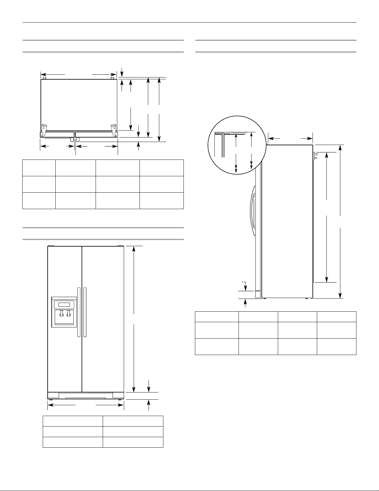
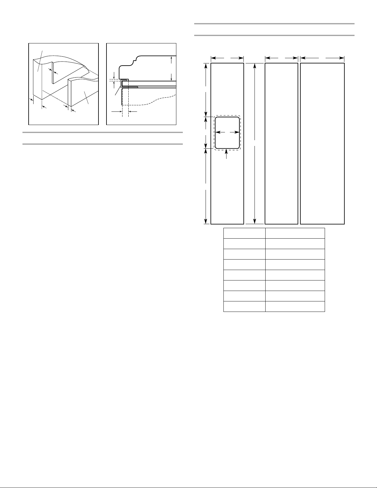
Product Dimensions
A
C
35¹⁄₂"
(90.0 cm)
23⁷⁄₈"
(60.4 cm)
15³⁄₈"
(38.9 cm)
20"
(50.8 cm)
B
⁵⁄₈"
(1.6 cm)
35³⁄₄"
(90.8 cm)
A
3
¹⁄₄"
(8.2 cm)
21³⁄₄"
(55.1 cm)
61¹⁄₄"
(155.6 cm)
3¹⁄₄" (8.2 cm)
C
A
B
Top View
Door
Style
Flat 27¹⁄₂"
Curved 28⁵⁄₈"
*Dimension may vary based on style of door handle.
The depth for the largest available handle is listed.
Depth
A
(69.8 cm)
(72.5 cm)
Depth
B
2⁵⁄₈"(6.5cm)
maximum*
2⁵⁄₈"
(6.5 cm)
30" (76.3 cm)
Depth
C
maximum*
31¹⁄₈"
(79.1 cm)
Side View
■ Height dimensions are shown with the leveling legs extended
to the minimum height of ¹⁄₄" (6.35 mm) below the refrigerator.
NOTE: When leveling legs are fully extended to 1" (25 mm)
below the refrigerator, add ³⁄₄" (19 mm) to the height
dimensions.
■ The power cord is 61¹⁄₄" (155.6 cm) long.
■ The water line attached to the back of the refrigerator is 78"
(198.1 cm) long.
Front View
Model Size Height A Height B Height C
69" 68⁷⁄₈"
(174.8 cm)
72" 71¹⁄₄"
(180.8 cm)
68⁷⁄₈"
(174.9 cm)
71¹⁄₄"
(180.9 cm)
68¹⁄₂"
(174.2 cm)
71"
(180.2 cm)
Model Size Height A
69" 65³⁄₄" (166.9 cm)
72" 68¹⁄₈" (172.9 cm)
3
Page 4
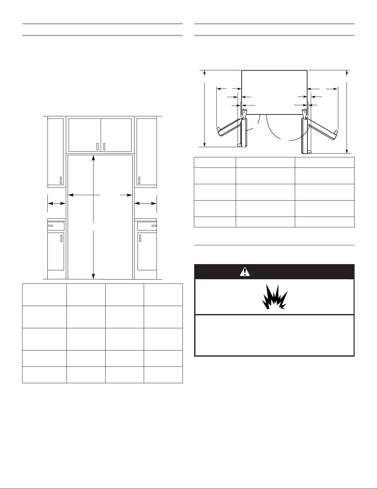
Opening Dimensions
36"
(91.4 cm)
B
C
A
A
41
¹⁄₄" (104.5 cm)
C
D
B
45⁷⁄₈" (116.4 cm)
90˚
165˚
C
D
WARNING
Explosion Hazard
Keep flammable materials and vapors, such as
gasoline, away from refrigerator.
Failure to do so can result in death, explosion, or fire.
Door Swing Dimensions
■ Height dimensions are shown with the leveling legs extended
to the minimum height of ¹⁄₄" (6.35 mm) below the refrigerator.
NOTE: When leveling legs are fully extended to 1" (25 mm)
below the refrigerator, add ³⁄₄" (19 mm) to the height
dimensions.
■ In the following graphic, “A” represents the opening height
required for standard cabinets. For full-overlay cabinet doors
with a trim kit, add ¹⁄₈" (0.3 cm).
■ In the following graphic, “B” represents the distance needed
to fully open the freezer door and “C” represents the distance
needed to fully open the refrigerator door.
■ Location must permit doors to open to a minimum of 165°.
■ In the following graphic, “A” represents the distance needed
to fully open the freezer door and “B” represents the distance
needed to fully open the refrigerator door.
Dimension Flat Doors Curved Doors
A 13⁵⁄₈" (34.5 cm)
13³⁄₄" (34.9 cm)
maximum*
B 18¹⁄₈" (46.0 cm)
18³⁄₈" (46.4 cm)
maximum*
C 2³⁄₄" (6.7 cm)
3³⁄₄" (9.4 cm)
maximum*
D ¹⁄₈" (0.2 cm) 1¹⁄₄" (2.9 cm)
Model Size
and
Height
A
Width
B
Door Style
69"
Flat
69"
(175.3 cm)
13⁵⁄₈"
(34.5 cm)
maximum*
72"
Flat
72"
(182.9 cm)
13⁵⁄₈"
(34.5 cm)
maximum*
69"
Curved
72"
Curved
69"
(175.3 cm)
72"
(182.9 cm)
13³⁄₄"
(34.9 cm)
13³⁄₄"
(34.9 cm)
*Dimension may vary based on style of door handle.
The width for the largest available handle is listed.
Width
C
18¹⁄₈"
(46.0 cm)
maximum*
18¹⁄₈"
(46.0 cm)
maximum*
18³⁄₈"
(46.4 cm)
18³⁄₈"
(46.4 cm)
*Dimension may vary based on style of door handle.
The width for the largest available handle is listed.
Location Requirements
NOTES:
■ The cabinet depth refrigerator can be installed into a recessed
opening, at the end of cabinets or as a freestanding
refrigerator.
■ If you are installing the refrigerator to fit flush with the front of
the base cabinets, all shoe molding and baseboards must be
removed from the rear of the refrigerator opening. Allow for
1" (2.54 cm) of space behind the refrigerator.
■ Location should permit doors to open fully. See the “Door
Swing Dimensions” section.
4
Page 5
■ This refrigerator is intended for use in a location where the
Electrical Shock Hazard
Plug into a grounded 3 prong outlet.
Do not remove ground prong.
Do not use an adapter.
Do not use an extension cord.
Failure to follow these instructions can result in death,
fire, or electrical shock.
WARNING
temperature ranges from a minimum of 55°F (13°C) to a
maximum of 110°F (43°C). The preferred room temperature
range for optimum performance, which reduces electricity
usage and provides superior cooling, is between 60°F (15°C)
and 90°F (32°C). It is recommended that you do not install the
refrigerator near a heat source, such as an oven or radiator.
■ Floor must support refrigerator weight (more than 600 lbs
[272 kg], door panels and contents).
Electrical Requirements
Before you move your refrigerator into its final location, it is
important to make sure you have the proper electrical connection.
Recommended Grounding Method
A 115 volt, 60 Hz, AC only 15- or 20-amp fused, grounded
electrical supply is required. It is recommended that a separate
circuit serving only your refrigerator be provided. Use an outlet
that cannot be turned off by a switch. Do not use an
extension cord.
IMPORTANT: If this product is connected to a GFCI (Ground Fault
Circuit Interrupter) protected outlet, nuisance tripping of the
power supply may occur, resulting in loss of cooling. Food quality
and flavor may be affected. If nuisance tripping has occurred, and
if the condition of the food appears poor, dispose of it.
NOTE: Before performing any type of installation, cleaning, or
removing a light bulb, turn the control (Thermostat, Refrigerator or
Freezer Control depending on the model) to OFF and then
disconnect the refrigerator from the electrical source. When you
are finished, reconnect the refrigerator to the electrical source and
reset the control (Thermostat, Refrigerator or Freezer Control
depending on the model) to the desired setting.
Water Supply Requirements
Gather the required tools and parts before starting installation.
Read and follow the instructions provided with any tools listed
here.
TOOLS NEEDED:
■ Flat-blade screwdriver
■ ⁷⁄₁₆" and ¹⁄₂" Open-end or two
adjustable wrenches
NOTE: Your refrigerator dealer has a kit available with a ¹⁄₄"
(6.35 mm) saddle-type shutoff valve, a union, and copper tubing.
Before purchasing, make sure a saddle-type valve complies with
your local plumbing codes. Do not use a piercing-type or ³⁄₁₆"
(4.76 mm) saddle valve which reduces water flow and clogs more
easily.
IMPORTANT:
■ All installations must meet local plumbing code requirements.
■ Use copper tubing and check for leaks. Install copper tubing
only in areas where the household temperatures will remain
above freezing.
Water Pressure
A cold water supply with water pressure of between 30 and
120 psi (207 and 827 kPa) is required to operate the ice maker. If
you have questions about your water pressure, call a licensed,
qualified plumber.
Reverse Osmosis Water Supply
IMPORTANT: The pressure of the water supply coming out of a
reverse osmosis system going to the water inlet valve of the
refrigerator needs to be between 30 and 120 psi (207 and
827 kPa).
If a reverse osmosis water filtration system is connected to your
cold water supply, the water pressure to the reverse osmosis
system needs to be a minimum of 40 to 60 psi (276 to 414 kPa).
If the water pressure to the reverse osmosis system is less than
40 to 60 psi (276 to 414 kPa):
■ Check to see whether the sediment filter in the reverse
osmosis system is blocked. Replace the filter if necessary.
■ Allow the storage tank on the reverse osmosis system to refill
after heavy usage.
■ If your refrigerator has a water filter, it may further reduce the
water pressure when used in conjunction with a reverse
osmosis system. Remove the water filter. See “Water Filtration
System” in the Use & Care Guide.
If you have questions about your water pressure, call a licensed,
qualified plumber.
■ ¹⁄₄" Nut driver
■ ¹⁄₄" Drill bit
■ Cordless drill
5
Page 6
INSTALLATION INSTRUCTIONS
WARNING
Excessive Weight Hazard
Use two or more people to move and install
refrigerator.
Failure to do so can result in back or other injury.
WARNING
Broken Glass Hazard
Do not hit refrigerator glass doors.
Protect glass surface and edges during installation or
removal of doors.
Failure to do so can result in serious eye injury or
minor cuts.
When Moving Your Refrigerator:
Your refrigerator is heavy. When moving the refrigerator for
cleaning or service, be sure to cover the floor with
cardboard or hardboard to avoid floor damage. Always pull
the refrigerator straight out when moving it. Do not wiggle or
“walk” the refrigerator when trying to move it, as floor
damage could occur.
Important information to know about glass shelves,
covers and door panels (on some models):
• Do not clean glass shelves or covers with warm water
when they are cold. Shelves and covers may break if
exposed to sudden temperature changes or impact, such
as bumping. Glass shelves and covers are heavy. Use
special care when removing them to avoid impact from
dropping.
• Do not hit the glass door panels with pots, pans, furniture,
toys or other objects. Scratching, hitting, jarring or
stressing the glass may weaken its structure, causing an
increased likelihood of breakage at a later date.
• For your protection, tempered glass is designed to shatter
into many small, pebble-size pieces. This is normal.
Decorative Panel
Spacer Panel
Backer Panel
3
/4"
(19.05 mm)
1
/₁₆"
(1.59 mm)
1
/4"
(6.35 mm)
1" minimum
(2.54 cm)
Door
Trim
Spacer Panel
1
/₁₆"
(1.59 mm)
Decorative Panel
Backer Panel
Unpack the Refrigerator
Remove the Packaging
Dispose of/recycle all packaging materials. Do not use sharp
instruments, rubbing alcohol, flammable fluids, or abrasive
cleaners to remove tape or glue. These products can damage the
surface of your refrigerator.
IMPORTANT:
■ Use ¹⁄₂" socket wrench to remove skids (socket extension is
recommended).
■ All four leveling legs must contact the floor to support and
stabilize the full weight of the refrigerator.
Clean Before Using
After you remove all of the package materials, clean the inside of
your refrigerator before using it. See the cleaning instructions in
the Use & Care Guide or User Instructions.
Custom Door Panels
(on some models)
Custom door panels allow you to blend the exterior of your
refrigerator into the overall kitchen décor. If you plan to install
custom wood panels, you will need to create the panels yourself
or consult a qualified cabinetmaker or carpenter. Follow these
panel dimension and placement instructions to be sure that the
custom panels will fit properly.
The custom panels must have backer panels attached in order to
mount them to the refrigerator. It is most common to work with
three panels, as shown in the following graphic: a ³⁄₄" (19.05 mm)
decorative panel, a ¹⁄₁₆" (1.59 mm) spacer panel or spacer strips,
and a ¹⁄₄" (6.35 mm) backer panel.
6
Page 7
NOTE: You can also work with two panels, as shown in the
Decorative Panel
Backer Panel
11
/16"
(17.46 mm)
1
/4"
(6.35 mm)
1" minimum
(2.54 cm)
1
/16"
(1.59 mm)
Door
Trim
1
/₁₆"
(1.59 mm)
Decorative
Panel
Backer Panel
3
/₄"
(19.05 mm)
F
B
E
DD
Freezer
Door Panel
(Non-Dispenser)
Refrigerator
Door Panel
G
C
Freezer
Door Panel
(Dispenser)
Dispenser
cutout is
centered
left-to-right
A
following graphic: a ³⁄₄" (19.05 mm) decorative panel routed with a
¹⁄₁₆" (1.59 mm) cutout, and a separate ¹⁄₄" (6.35 mm) backer panel.
Weight Limits
IMPORTANT: Panels weighing more than the recommended
weight may cause damage to your refrigerator.
■ The weight of the freezer door panel(s) cannot exceed
25 lbs (11.3 kg).
■ The weight of the refrigerator door panel(s) cannot exceed
41 lbs (18.6 kg).
To minimize panel weight, you may use 2" (5.08 cm) spacer strips
around the perimeter in place of solid full-sheet spacer panels.
The spacer strips must be set in at least 1" (2.54 cm) from the top,
bottom and side edges of the backer panel. If you use spacer
strips, it is also recommended that you use two
horizontally-centered 2" (5.08 cm) strips for added support.
Decorative Panel Dimensions
NOTE: The dashed line represents the placement of the dispenser
frame.
Dimension Height/Width
A 19³⁄₈" (49.2 cm)
B 31³⁄₄" (80.6 cm)
C 68³⁄₁₆" (173.2 cm)
D 15³⁄₈" (39.1 cm)
E 20" (50.8 cm)
F 17¹⁄₁₆" (43.3 cm)
G 11¹⁵⁄₃₂" (29.1 cm)
7
Page 8
Backer and Spacer Panel Dimensions
E
A
B
C
D D
D
C
A
NOTE: The dashed lines represent the placement of the backer
and spacer panels on the decorative panels. Backer and spacer
panels should be centered vertically and horizontally.
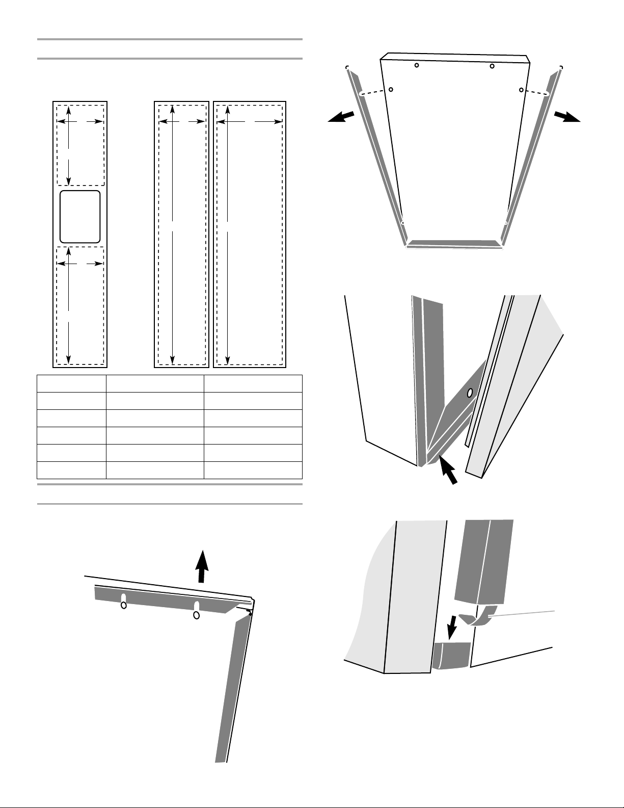
2. Remove the side trim from each side of the freezer door.
3. Align the bottom edge of the door panel with the lower trim on
the bottom of the freezer door. Center the panel on the freezer
door.
Dimension Backer Panel Spacer Panel
A 19" (48.3 cm) 18³⁄₈" (46.7 cm)
B 31¹⁵⁄₃₂" (79.9 cm) 30³⁄₄" (78.1 cm)
C 67²⁹⁄₃₂" (172.5 cm) 66⁹⁄₁₆" (169.1 cm)
D 14⁷⁄₈" (37.8 cm) 14¹⁄₄" (36.2 cm)
E 19¹⁄₂" (49.6 cm) 18⁷⁄₈" (47.9 cm)
Install the Door Panels
NOTE: In the graphics throughout this section, dark gray
represents the door trim and light gray represents the door panel.
1. Remove the upper trim from the top of the freezer door.
4. Reseat each side trim, making sure the trim clip slides inside
the corner of the lower trim.
A. Trim clip
8
Page 9
5. With the side trims properly seated in the lower trim, slide
A
each trim into the door panel groove.
6. Align the upper trim with the trim clips at the top of each side
trim.
8. When fully seated, the upper trim should be nearly flush with
the top of the freezer door, completely covering both side trim
clips.
9. Repeat the previous steps to install the refrigerator door
panel.
Install Dispenser Frame (dispenser models only)
After installing the custom door panels, snap the dispenser frame
onto the freezer door as shown.
A. Trim clip
7. Slide the upper trim into the door panel groove by applying
firm downward pressure. Be sure that the grooves on the
upper trim are properly aligned with the rivets on the door
panel.
Connect Water Supply
Read all directions before you begin.
IMPORTANT:
■ Plumbing shall be installed in accordance with the
International Plumbing Code and any local codes and
ordinances.
■ The gray water tubing on the back of the refrigerator (which is
used to connect to the household water line) is a PEX
(cross-linked polyethylene) tube. Copper and PEX tubing
connections from the household water line to the refrigerator
are acceptable, and will help avoid off-taste or odor in your ice
or water. Check for leaks.
If PEX tubing is used instead of copper, we recommend the
following Whirlpool Part Numbers:
W10505928RP (7 ft [2.14 m] jacketed PEX),
8212547RP (5 ft [1.52 m] PEX), or
W10267701RP (25 ft [7.62 m] PEX).
■ Install tubing only in areas where temperatures will remain
above freezing.
TOOLS NEEDED:
Gather the required tools and parts before starting installation.
■ Flat-blade screwdriver
■ ⁷⁄₁₆" and ¹⁄₂" open-end wrenches or two adjustable wrenches
■ ¹⁄₄" nut driver
9
Page 10
Connect to Water Line
A
B
D
C
B CA
A
B
C
DEF
G
D
A B C
IMPORTANT: If you turn the refrigerator on before the water line is
connected, turn the ice maker OFF.
Style 1 (Recommended)
1. Unplug refrigerator or disconnect power.
2. Turn OFF main water supply. Turn ON nearest faucet long
enough to clear line of water.
3. Use a quarter-turn shutoff valve or the equivalent, served by a
¹⁄₂" copper household supply line.
NOTE: To allow sufficient water flow to the refrigerator, a
minimum ¹⁄₂" size copper household supply line is
recommended.
A. Bulb
B. Nut
4. Now you are ready to connect the copper tubing to the shutoff
valve. Use ¹⁄₄" (6.35 mm) OD soft copper tubing to connect the
shutoff valve and the refrigerator.
■ Ensure that you have the proper length needed for the job.
Be sure both ends of the copper tubing are cut square.
■ Slip compression sleeve and compression nut onto
copper tubing as shown. Insert end of tubing into outlet
end squarely as far as it will go. Screw compression nut
onto outlet end with adjustable wrench. Do not
overtighten.
A. Compression sleeve
B. Compression nut
5. Place the free end of the tubing into a container or sink, and
turn on main water supply to flush out tubing until water is
clear. Turn off shutoff valve on the water pipe.
NOTE: Always drain the water line before making the final
connection to the inlet of the water valve, to avoid possible
water valve malfunction.
6. Bend the copper tubing to meet the water line inlet, which is
located on the back of the refrigerator cabinet as shown.
Leave a coil of copper tubing to allow the refrigerator to be
pulled out of the cabinet or away from the wall for service.
C. Copper tubing (to refrigerator)
D. Household supply line (½" minimum)
C. Copper tubing
4. Determine the length of copper tubing you need. Measure
from the connection on the lower rear corner of refrigerator to
the water pipe. Add 7 ft (2.1 m) to allow for cleaning. Use ¹⁄₄"
(6.35 mm) O.D. (outside diameter) copper tubing. Be sure both
ends of copper tubing are cut square.
5. Using a cordless drill, drill a ¹⁄₄" (6.35 mm) hole in the cold
water pipe you have selected.
A. Cold water pipe
B. Pipe clamp
C. Copper tubing
D. Compression nut
E. Compression sleeve
F. Shutoff valve
G. Packing nut
6. Fasten the shutoff valve to the cold water pipe with the pipe
clamp. Be sure the outlet end is solidly in the ¹⁄₄" (6.35 mm)
drilled hole in the water pipe and that the washer is under the
pipe clamp. Tighten the packing nut. Tighten the pipe clamp
screws slowly and evenly so the washer makes a watertight
seal. Do not overtighten, or you may crush the copper tubing.
7. Slip the compression sleeve and compression nut on the
copper tubing as shown. Insert the end of the tubing into the
outlet end squarely as far as it will go. Screw the compression
nut onto outlet end with adjustable wrench. Do not
overtighten.
8. Place the free end of the tubing in a container or sink, and turn
ON the main water supply. Flush the tubing until water is clear.
Turn OFF the shutoff valve on the water pipe. Coil the copper
tubing.
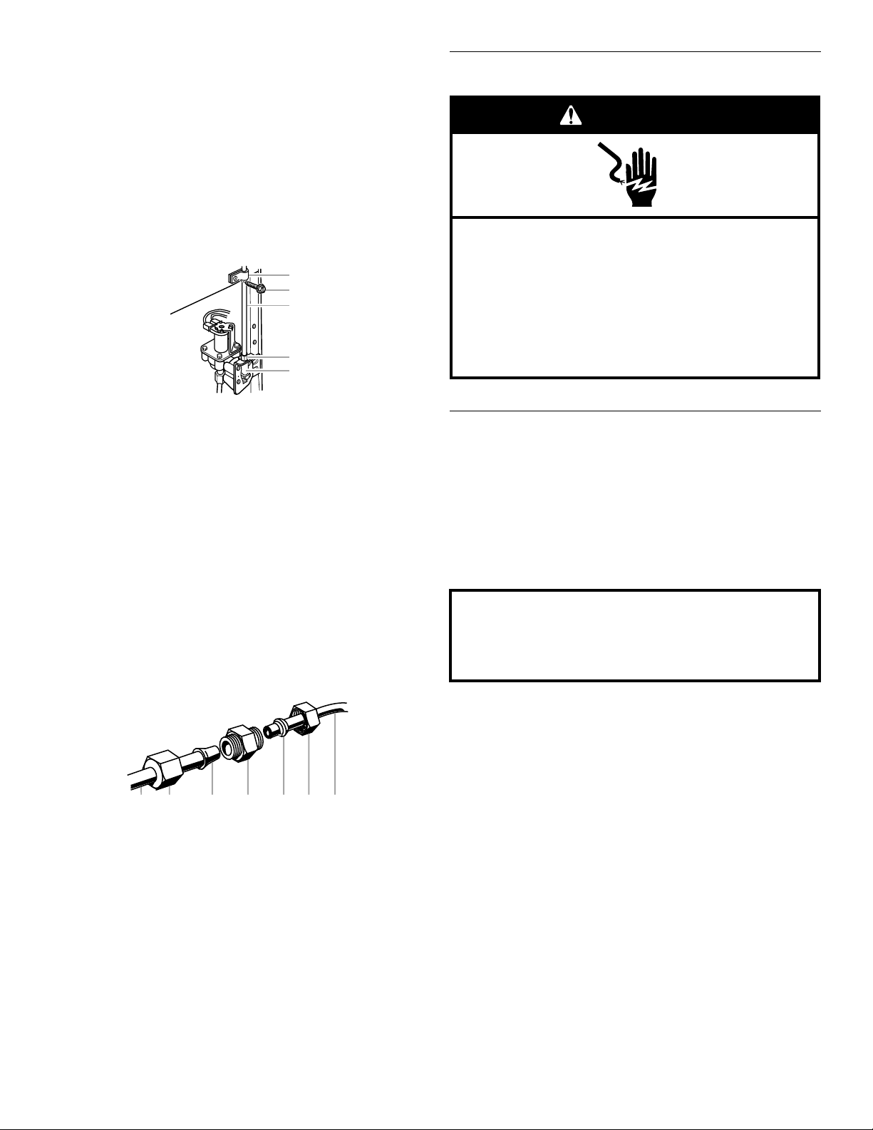
Connect to Refrigerator
Style 1
1. Unplug refrigerator or disconnect power.
2. Remove and discard the short, black plastic part from the end
of the water line inlet.
3. Thread the nut onto the end of the tubing. Tighten the nut by
hand. Then tighten it with a wrench two more turns. Do not
overtighten.
NOTE: To avoid rattling, be sure the copper tubing does not
touch the cabinet’s side wall or other parts inside the cabinet.
A. Household water line
B. Nut (purchased)
C. Ferrule (purchased)
D. Refrigerator water tubing
Style 2
1. Unplug refrigerator or disconnect power.
2. Turn OFF main water supply. Turn ON nearest faucet long
enough to clear line of water.
3. Locate a
pipe near the refrigerator.
IMPORTANT:
■ Make sure it is a cold water pipe.
■ Horizontal pipe will work, but drill on the top side of the
pipe, not the bottom. This will help keep water away from
the drill and normal sediment from collecting in the valve.
10
¹⁄₂" (1.27 cm) to 1¹⁄₄" (3.18 cm) vertical cold water
4. Install the water supply tube clamp around the water supply
line to reduce strain on the coupling.
5. Turn shutoff valve ON.
6. Check for leaks. Tighten any connections (including
connections at the valve) or nuts that leak.
Page 11
Style 2
A
C
B
D
E
A B C D E F G
Electrical Shock Hazard
Plug into a grounded 3 prong outlet.
Do not remove ground prong.
Do not use an adapter.
Do not use an extension cord.
Failure to follow these instructions can result in death,
fire, or electrical shock.
WARNING
Do not use with water that is microbiologically unsafe or
of unknown quality without adequate disinfection before
or after the system. Systems certified for cyst reduction
may be used on disinfected waters that may contain
filterable cysts.
1. Unplug refrigerator or disconnect power.
2. Remove and discard the plastic part that is attached to the
inlet of the water valve.
3. Attach the copper tube to the valve inlet using a compression
nut and sleeve as shown. Tighten the compression nut. Do not
overtighten.
4. Use the tube clamp on the back of the refrigerator to secure
the tubing to the refrigerator as shown. This will help avoid
damage to the tubing when the refrigerator is pushed back
against the wall.
5. Turn shutoff valve ON.
6. Check for leaks. Tighten any connections (including
connections at the valve) or nuts that leak.
Plug in Refrigerator
A. Tube clamp
B. Tube clamp screw
C. Copper tubing
7. On some models, the ice maker is equipped with a built-in
water strainer. If your water conditions require a second water
strainer, install it in the ¹⁄₄" (6.35 mm) water line at either tube
connection. Obtain a water strainer from your nearest
appliance dealer.
D. Compression nut
E. Valve inlet
Style 3
1. Unplug refrigerator or disconnect power.
2. Remove and discard the black nylon plug from the gray water
tube on the rear of the refrigerator.
3. If the gray water tube supplied with the refrigerator is not long
enough, a ¹⁄₄" x ¹⁄₄" (6.35 mm x 6.35 mm) coupling is needed in
order to connect the water tubing to an existing household
water line. Thread the provided nut onto the coupling on the
end of the copper tubing.
NOTE: Tighten the nut by hand. Then tighten it with a wrench
two more turns. Do not overtighten.
A. Refrigerator water tubing
B. Nut (provided)
C. Bulb
D. Coupling (purchased)
4. Turn shutoff valve ON.
5. Check for leaks. Tighten any nuts or connections (including
connections at the valve) that leak.
E. Ferrule (purchased)
F. Nut (purchased)
G. Household water line
1. Plug into a grounded 3 prong outlet.
Prepare the Water System
Please read before using the water system.
Immediately after installation, follow the steps below to make sure
that the water system is properly cleaned.
1. Open the freezer door and turn off the ice maker. The On/Off
switch can only be accessed when the ice storage bin has
been removed. The switch is located on the freezer door, on
the left side of the wall that surrounds the ice storage bin.
Move the switch to the OFF (right) setting.
2. Make sure the water filter is properly installed.
3. Open the freezer door and turn on the ice maker. Move the
switch to the ON (left) position. See the Use & Care Guide or
User Instructions for further instructions on the operation of
your ice maker.
■ Allow 24 hours to produce the first batch of ice.
■ Discard the first three batches of ice produced.
■ Depending on your model, you may want to select the
maximum ice feature to increase the production of ice.
11
Page 12

Leveling and Door Closing
A
B
C
Raise
Lower
A
Raise
Lower
Your refrigerator has two adjustable front feet — one on the right
and one on the left. In most cases, the refrigerator should be
steady when both feet are touching the floor. If your refrigerator
seems unsteady or if you want the doors to close more easily,
adjust the refrigerator's tilt using the instructions below:
1. Move the refrigerator into its final location. Open both doors
to 90°. Remove the base grille by removing the two screws,
then pulling out on the outside corners.
NOTE: The doors must only be opened to 90°. If they are
opened all the way, the base grille will not come off.
2. The two leveling feet are located on the brackets on each side
of the product.
Door Alignment
A refrigerator that is not level from side-to-side may appear to
have doors that are not properly aligned. If the doors appear this
way, use the instructions in the previous section to check the
leveling.
The doors are designed to be slightly different heights when the
refrigerator is empty, in order to account for the weight of food
that will be placed on the doors. If the doors are still not aligned
after checking the leveling and loading the refrigerator with food,
follow the steps below to adjust the door alignment.
1. If necessary, open both doors to 90° and remove the base
grille.
2. Locate the alignment screw on the bottom hinge of the
refrigerator door.
A. Bottom hinge
B. Leveler bracket
C. Leveling foot
NOTE: Having someone push against the top of the refrigerator
takes some weight off the leveling feet. This makes it easier to
make adjustments.
3. Use a ¹⁄₄" open-ended or adjustable wrench to adjust the
leveling feet. Turn the leveling foot to the left to raise that side
of the product, or turn it to the right to lower that side of the
product.
4. Open both doors again and check that they close as easily as
you like. If not, tilt the refrigerator slightly more to the rear by
turning the leveling feet to the left. It may take several more
turns, and you should turn both leveling feet the same
amount.
NOTE: Whenever you need to move the refrigerator, turn the
leveling feet to the right until they are no longer touching the
ground. This will allow the refrigerator to roll more easily.
A. Alignment screw
3. Use a ⁵⁄₁₆" open-ended or adjustable wrench to turn the screw.
To raise the refrigerator door, turn the screw to the right. To
lower the door, turn the screw to the left.
4. Check that the doors are even at the top. If necessary,
continue to turn the alignment screw until the doors are
aligned.
5. Open both doors to 90°. Replace the base grille.
Complete Installation
1. Turn water supply line valve to “Open” position.
2. Turn refrigerator switch to ON position. Wait a few minutes.
Check water line connections for leaks.
3. Set refrigerator and freezer compartment controls to the
midpoint setting. Check that the compressor is operating
properly and that all lights are working.
NOTE: If construction will continue after refrigerator has been
installed, set controls to OFF.
If refrigerator does not operate
■ Check that the circuit breaker is not tripped or household fuse
blown.
■ Check that the power supply cord is plugged into a grounded
3prong outlet.
■ See “Problem Solver” or “Troubleshooting” in the Use & Care
Guide or User Instructions.
12
Page 13

INSTRUCCIONES DE INSTALACIÓN
Si no sigue las instrucciones de inmediato, usted puede
morir o sufrir una lesión grave.
Si no sigue las instrucciones, usted puede morir o sufrir
una lesión grave.
Todos los mensajes de seguridad le dirán el peligro potencial, le dirán cómo reducir las posibilidades de sufrir una lesión y lo que
puede suceder si no se siguen las instrucciones.
Su seguridad y la seguridad de los demás es muy importante.
Hemos incluido muchos mensajes importantes de seguridad en este manual y en su electrodoméstico. Lea y obedezca siempre
todos los mensajes de seguridad.
ADVERTENCIA
PELIGRO
Este es el símbolo de advertencia de seguridad.
Este símbolo le llama la atención sobre peligros potenciales que pueden ocasionar la muerte o una lesión a
usted y a los demás.
Todos los mensajes de seguridad irán a continuación del símbolo de advertencia de seguridad y de la palabra
“PELIGRO” o “ADVERTENCIA”. Estas palabras significan:
Advertencias de la Proposición 65 del estado de California:
ADVERTENCIA: Este producto contiene una o más sustancias químicas identificadas por el estado de California como
causantes de cáncer.
ADVERTENCIA: Este producto contiene una o más sustancias químicas identificadas por el estado de California como
causantes de defectos congénitos o algún otro tipo de daños en la función reproductora.
Refrigerador de dos puertas con profundidad de mostrador
Ayuda o servicio técnico
Si tiene preguntas
Si usted tiene preguntas acerca del funcionamiento, la limpieza o
el mantenimiento de su refrigerador, vea las Instrucciones para el
usuario.
Si necesita servicio
Para mantener la calidad de su refrigerador, llame a una compañía
de servicio autorizada.
Para ubicar una compañía de servicio autorizada, vea las
Instrucciones para el usuario para saber a qué número tiene que
llamar, llame al distribuidor en donde compró el refrigerador o
fíjese en las páginas amarillas de su guía telefónica local.
SEGURIDAD DEL REFRIGERADOR
Guarde este libro y su comprobante de compra juntos para
referencia futura. Usted deberá proporcionar evidencia de la
compra o una fecha de instalación para obtener servicio bajo
la garantía.
Escriba la siguiente información acerca de su electrodoméstico
para ayudarle a obtener asistencia o servicio técnico si alguna vez
llegara a necesitarlo. Deberá tener a mano el número completo
del modelo y de la serie. Puede encontrar esta información en la
etiqueta con el número de modelo y de serie que está ubicada en
la pared interior del compartimiento del refrigerador.
Nombre del distribuidor _________________________________________
Número de serie ________________________________________________
Dirección_______________________________________________________
Número de teléfono_____________________________________________
Número del modelo _____________________________________________
Fecha de compra _______________________________________________
13
Page 14

REQUISITOS DE INSTALACIÓN
A
C
35¹⁄₂"
(90,0 cm)
23⁷⁄₈"
(60,4 cm)
15³⁄₈"
(38,9 cm)
20"
(50,8 cm)
B
⁵⁄₈"
(1,6 cm)
35³⁄₄"
(90,8 cm)
A
3
¹⁄₄"
(8,2 cm)
Piezas y herramientas
IMPORTANTE:
■ Observe todos los códigos y reglamentos aplicables.
■ Instalador: Deje las instrucciones de instalación con el
propietario.
■ Propietario: Guarde las instrucciones de instalación para
referencia futura y para que puedan ser usadas por el
inspector eléctrico local.
■ Mantenga un tramo de cartón de empaque o de madera
contrachapada debajo del refrigerador hasta que lo instale en
su ubicación final.
■ Cumpla con las especificaciones y medidas de instalación.
■ Saque todas las molduras o paneles decorativos de los
armarios de la cocina que impidan el acceso al refrigerador
para darle servicio.
■ Contacte a un instalador electricista calificado.
HERRAMIENTAS NECESARIAS (en algunos modelos):
Reúna las herramientas y piezas necesarias antes de comenzar la
instalación. Lea y siga las instrucciones provistas con cualquiera
de las herramientas enlistadas aquí.
■ Taladro inalámbrico
■ Llave para tuercas
de ¹⁄₄"y broca
■ Destornillador de
hoja plana
PIEZAS NECESARIAS (en algunos modelos):
■ El distribuidor de su refrigerador tiene un juego disponible de
válvula de cierre tipo montura de ¼" (6,35 mm), una unión y
tubería de cobre.
■ O usted puede comprar una tubería de cobre de ¼" (6,35 mm)
con válvula de cierre y un accesorio de compresión
(acoplamiento) de ¼" (6,35 mm).
■ Dependiendo de las conexiones de la línea de agua, usted
también puede necesitar una tuerca de ¼" (6,35 mm) y una
férula de ¼" (6,35 mm).
■ Llave de ⁵⁄₁₆" o llave ajustable
■ Llaves de boca de ⁷⁄₁₆"y¹⁄₂"
■ Dos llaves ajustables
■ Llaves de cubo de ³⁄₈"y¹⁄₂"
Medidas del producto
Vista superior
Estilo de
puerta
Plana 27¹⁄₂"
Curva 28⁵⁄₈"
*Las dimensiones pueden variar según el estilo de la manija de la
puerta. Se indica la profundidad para la manija más grande que
hay disponible.
Vista frontal
ProfundidadAProfundidadBProfundidad
C
(69,8 cm)
(72,5 cm)
2⁵⁄₈"(6,5cm)
máxima*
2⁵⁄₈"
(6,5 cm)
30" (76,3 cm)
máxima*
31¹⁄₈"
(79,1 cm)
14
Tamaño del modelo Altura A
69" 65³⁄₄" (166,9 cm)
72" 68¹⁄₈" (172,9 cm)
Page 15

Vista lateral
21³⁄₄"
(55,1 cm)
61¹⁄₄"
(155,6 cm)
3¹⁄₄" (8,2 cm)
C
A
B
36"
(91,4 cm)
B
C
A
Medidas de abertura
■ Las medidas de altura indicadas consideran las patas
niveladoras extendidas como mínimo ¼" (6,35 mm) por
debajo del refrigerador.
NOTA: Si las patas niveladoras están totalmente extendidas
1" (25 mm) por debajo del refrigerador, agregue ³⁄₄" (19 mm) a
las medidas de altura.
■ El cable de suministro de energía es de 61¹⁄₄" (155,6 cm) de
largo.
■ La línea de agua ajustada a la parte posterior del refrigerador
es de 78" (198,1 cm) de largo.
■ Las medidas de altura indicadas consideran las patas
niveladoras extendidas como mínimo ¼" (6,35 mm) por
debajo del refrigerador.
NOTA: Si las patas niveladoras están totalmente extendidas
1" (25 mm) por debajo del refrigerador, agregue ³⁄₄" (19 mm) a
las medidas de altura.
■ En la ilustración a continuación, “A” representa la altura de
abertura necesaria para los armarios estándar. Para las
puertas de armarios completamente recubiertos con juego de
molduras, agregue ¹⁄₈" (0,3 cm).
■ En la ilustración a continuación, “B” representa la distancia
necesaria para abrir por completo la puerta del congelador y
“C” representa la distancia necesaria para abrir por completo
la puerta del refrigerador.
Tamaño del
modelo
69" 68⁷⁄₈"
72" 71¹⁄₄"
Altura A Altura B Altura C
(174,8 cm)
(180,8 cm)
(174,9 cm)
(180,9 cm)
68⁷⁄₈"
71¹⁄₄"
68¹⁄₂"
(174,2 cm)
71"
(180,2 cm)
Tamaño del
modelo y
Altura
A
Ancho
B
Ancho
C
estilo de puerta
69"
Plana
72"
Plana
69"
Curva
72"
Curva
69"
(175,3 cm)
72"
(182,9 cm)
69"
(175,3 cm)
72"
(182,9 cm)
13⁵⁄₈"
(34,5 cm)
máximo*
13⁵⁄₈"
(34,5 cm)
máximo*
13³⁄₄"
(34,9 cm)
13³⁄₄"
(34,9 cm)
18¹⁄₈"
(46,0 cm)
máximo*
18¹⁄₈"
(46,0 cm)
máximo*
18³⁄₈"
(46,4 cm)
18³⁄₈"
(46,4 cm)
*Las dimensiones pueden variar según el estilo de la manija de la
puerta. Se indica el ancho para la manija más grande que hay
disponible.
15
Page 16

Medidas de oscilación de las puertas
A
41
¹⁄₄" (104,5 cm)
C
D
B
45⁷⁄₈" (116,4 cm)
90˚
165˚
C
D
ADVERTENCIA
Peligro de Explosión
Mantenga los materiales y vapores inflamables,
tales como gasolina, alejados del refrigerador.
No seguir esta instrucción puede ocasionar la muerte,
explosión, o incendio.
ADVERTENCIA
Peligro de Choque Eléctrico
Conecte a un contacto de pared de conexión a tierra de
3 terminales.
No quite la terminal de conexión a tierra.
No use un adaptador.
No use un cable eléctrico de extensión.
No seguir estas instrucciones puede ocasionar
la muerte, incendio o choque eléctrico.
■ La ubicación debe permitir que las puertas se abran a un
mínimo de 165°.
■ En la ilustración a continuación, “A” representa la distancia
necesaria para abrir por completo la puerta del congelador y
“B” representa la distancia necesaria para abrir por completo
la puerta del refrigerador.
Dimensión Puertas planas Puertas curvas
A 13⁵⁄₈" (34,5 cm)
máximo*
13³⁄₄" (34,9 cm)
■ Este refrigerador ha sido diseñado para usarse en un lugar en
donde los rangos de temperatura varíen entre un mínimo de
55°F (13°C) y un máximo de 110°F (43°C). Para un óptimo
rendimiento, el rango preferido de temperatura de la
habitación (que reduce el uso de electricidad y provee un
enfriamiento superior) es entre 60°F (15°C) y 90°F (32°C). No
se recomienda instalar el refrigerador cerca de una fuente de
calor, como puede ser un horno o un radiador.
■ El piso debe soportar el peso del refrigerador (más de 600 lbs
[272 kg], los paneles de las puertas y el contenido).
Requisitos eléctricos
B 18¹⁄₈" (46,0 cm)
18³⁄₈" (46,4 cm)
máximo*
C 2³⁄₄" (6,7 cm)
3³⁄₄" (9,4 cm)
máximo*
D ¹⁄₈" (0,2 cm) 1¹⁄₄" (2,9 cm)
*Las dimensiones pueden variar según el estilo de la manija de la
puerta. Se indica el ancho para la manija más grande que hay
disponible.
Requisitos de ubicación
NOTAS:
■ El refrigerador con profundidad de armario puede instalarse
■ Si va a instalar el refrigerador para estar alineado con el frente
■ La ubicación deberá permitir que las puertas se abran
16
empotrado, al final de los armarios o por separado.
de los armarios de base, se deben quitar todas las molduras y
los zócalos de la parte posterior de la abertura del
refrigerador. Deje un espacio de 1" (2,54 cm) detrás del
refrigerador.
completamente. Vea la sección “Medidas de oscilación de las
puertas”.
Antes de mover el refrigerador a su posición definitiva, es
importante asegurarse que Ud. tiene la conexión eléctrica
adecuada.
Método de conexión a tierra recomendado
Se requiere una fuente de energía eléctrica de 115 Voltios, 60 Hz.,
CA solamente y con fusibles de 15 ó 20 amperios, conectada a
tierra. Se recomienda que se use un circuito separado sólo para
su refrigerador. Use un tomacorriente que no se puede apagar
con un interruptor. No use un cable eléctrico de extensión.
IMPORTANTE: Si este producto está conectado a un
tomacorriente protegido por GFCI (Ground Fault Circuit
Interrupter - Interruptor de circuito de falla eléctrica de puesta a
tierra), puede ocurrir un disparo molesto del suministro de
corriente, lo que resultará en la pérdida de refrigeración. Esto
puede afectar la calidad y el sabor de los alimentos. Si ha
ocurrido un disparo molesto, y el alimento aparenta estar en
malas condiciones, deshágase del mismo.
NOTA: Antes de realizar cualquier tipo de instalación, limpieza o
de quitar un foco de luz, ponga el control (del termostato, del
refrigerador o del congelador dependiendo del modelo) en la
posición OFF (Apagado) y luego desconecte el refrigerador de la
fuente de energía. Cuando Ud. haya terminado, reconecte el
refrigerador a la fuente de energía eléctrica y vuelva a poner el
control (del termostato, del refrigerador o del congelador
dependiendo del modelo) en la posición deseada.
Page 17

Requisitos del suministro de agua
ADVERTENCIA
Peligro de Peso Excesivo
Use dos o más personas para mover e instalar
el refrigerador.
No seguir esta instrucción puede ocasionar una
lesión en la espalda u otro tipo de lesiones.
ADVERTENCIA
Peligro debido a vidrios rotos
No golpee las puertas de vidrio del refrigerador.
Proteja la superficie y los bordes del vidrio durante la
instalación o remoción de las puertas.
No seguir estas instrucciones puede ocasionar
lesiones graves en los ojos o cortaduras pequeñas.
Cómo mover su refrigerador:
Su refrigerador es pesado. Cuando mueva el refrigerador
para limpiarlo o para darle servicio, cerciórese de cubrir
el piso con cartón o madera para evitar daños en el mismo.
Al mover el refrigerador, siempre tire directamente hacia
afuera. No menee el refrigerador de lado a lado ni lo haga
“caminar” cuando lo trate de mover ya que podría dañar
el piso.
Reúna las herramientas y piezas necesarias antes de comenzar la
instalación. Lea y siga las instrucciones provistas con cualquiera
de las herramientas enlistadas aquí.
HERRAMIENTAS NECESARIAS:
■ Destornillador de hoja plana
■ Llaves de boca de ⁷⁄₁₆" y ¹⁄₂"
o dos llaves ajustables
■ Llave para tuercas de ¹⁄₄"
■ Broca de ¹⁄₄"
■ Taladro inalámbrico
INSTRUCCIONES DE
INSTALACIÓN
Desempaque el refrigerador
NOTA: El distribuidor de su refrigerador tiene un juego disponible
con una válvula de cierre tipo montura de
unión y tubería de cobre. Antes de comprar, asegúrese que la
válvula tipo montura cumpla con los códigos de plomería de su
localidad. No use una válvula perforadora o una válvula de
montura de
obstruye con más facilidad.
IMPORTANTE:
■ Todas las instalaciones deben hacerse de acuerdo a los
requerimientos locales de plomería.
■ Use tuberías de cobre y revise si hay fugas. Instale tubería de
cobre sólo en áreas donde la temperatura va a permanecer
por encima del punto de congelación.
³⁄₁₆" (4,76 mm) que reduce el flujo de agua y se
¹⁄₄" (6,35 mm), una
Presión del agua
Se necesita un suministro de agua fría con presión de agua entre
30 y 120 lbs/pulg² (207 y 827 kPa) para hacer funcionar la fábrica
de hielo. Si usted tiene preguntas acerca de la presión de agua,
llame a un plomero competente autorizado.
Suministro de agua de ósmosis inversa
IMPORTANTE: La presión del suministro de agua que sale de un
sistema de ósmosis inversa y va a la válvula de entrada de agua
del refrigerador necesitará ser entre 30 y 120 lbs/pulg² (207 y
827 kPa).
Si se conecta un sistema de filtración de agua de ósmosis inversa
al suministro de agua fría, la presión de agua al sistema de
ósmosis inversa necesitará ser de un mínimo de 40 a 60 lbs/pulg²
(276 a 414 kPa).
Si la presión del agua del sistema de ósmosis inversa es menor de
40 a 60 lbs/pulg² (276 a 414 kPa):
■ Fíjese si el filtro de sedimentos en el sistema de ósmosis
inversa está bloqueado y reemplácelo si fuera necesario.
■ Deje que se vuelva a llenar el tanque de almacenaje del
sistema de ósmosis inversa después del uso intenso.
■ Si su refrigerador tiene un cartucho del filtro de agua, se podrá
reducir la presión aún más si se usa en conjunto con un
sistema de ósmosis inversa. Quite el cartucho del filtro de
agua. Vea “Sistema de filtración de agua” en el Manual de uso
y cuidado.
Si tiene preguntas acerca de la presión del agua, llame a un
plomero competente autorizado.
Cómo quitar los materiales de empaque
Deshágase de todos los materiales de embalaje o recíclelos. No
use instrumentos filosos, alcohol para fricciones, líquidos
inflamables o productos de limpieza abrasivos para eliminar los
restos de cinta o goma. Estos productos pueden dañar la
superficie de su refrigerador.
IMPORTANTE:
■ Use una llave de cubo de ¹⁄₂" para quitar la plataforma (se
recomienda usar una extensión para llave de cubo).
■ Las cuatro patas niveladoras deberán tocar el piso para
soportar y estabilizar el peso total del refrigerador.
17
Page 18

Cómo limpiar su refrigerador antes de usarlo
Información importante para saber acerca de los
estantes, cubiertas y paneles de las puertas de vidrio
(en algunos modelos):
• No limpie los estantes y tapas de vidrio con agua caliente
mientras están fríos. Los estantes y tapas pueden
romperse si se exponen a cambios bruscos de
temperatura o impacto, como sería un golpe brusco. Los
estantes y tapas de vidrio son muy pesados. Tenga un
cuidado especial al quitarlos, para evitar el impacto al
caerse.
• No golpee el vidrio con ollas, sartenes, muebles, juguetes
ni otros objetos. Si se raya, golpea, sacude o se ejerce
presión sobre el vidrio, su estructura puede debilitarse, lo
que aumentará la probabilidad de rupturas en fechas
posteriores.
• Para su protección, el vidrio templado se ha diseñado
para hacerse añicos. Esto es normal.
Panel decorativo
Panel espaciador
Panel de
soporte
3
/4"
(19,05 mm)
1
/₁₆"
(1,59 mm)
1
/4"
(6,35 mm)
1" mínimo
(2,54 cm)
Panel de soporte
Panel decorativo
Moldura
de la
puerta
Panel espaciador
1
/₁₆"
(1,59 mm)
Moldura
de la
puerta
Panel decorativo
Panel de
soporte
11
/16"
(17,46 mm)
1
/4"
(6,35 mm)
1" mínimo
(2,54 cm)
1
/16"
(1,59 mm)
1
/₁₆"
(1,59 mm)
Panel
decorativo
Panel de soporte
3
/₄"
(19,05 mm)
Una vez que usted haya quitado todos los materiales de
empaque, limpie el interior de su refrigerador antes de usarlo. Vea
las instrucciones de limpieza en el Manual de uso y cuidado o las
Instrucciones para el usuario.
Paneles para puerta a la medida
(en algunos modelos)
Los paneles de la puerta a la medida le permiten armonizar el
exterior de su refrigerador con la decoración de la cocina. Si va a
instalar paneles de madera a la medida, deberá hacerlos usted
mismo o consultar un carpintero o fabricante de gabinetes
calificado. Siga estas instrucciones para las medidas y la
ubicación de los paneles, para asegurarse de que los paneles a la
medida encajen adecuadamente.
Los paneles a la medida deben tener paneles de soporte
instalados para montarlos en el refrigerador. Lo más común es
trabajar con tres paneles, como se muestra en la siguiente
gráfica: un panel decorativo de ³⁄₄" (19,05 mm), un panel
espaciador de ¹⁄₁₆" (1,59 mm) o tiras espaciadoras, y un panel de
soporte de ¹⁄₄" (6,35 mm).
NOTA: También puede trabajar con dos paneles, como se
muestra en la ilustración siguiente: un panel decorativo de ³⁄₄"
(19,05 mm), contorneado con un recorte de ¹⁄₁₆" (1,59 mm), y un
panel de soporte de ¹⁄₄" (6,35 mm) por separado.
Límites de peso
IMPORTANTE: Los paneles que pesan más de lo recomendado
pueden dañar su refrigerador.
■ El peso del (de los) panel(es) de la puerta del congelador no
debe sobrepasar las 25 lb (11,3 kg).
■ El peso del (de los) panel(es) de la puerta del refrigerador no
debe sobrepasar las 41 lb (18,6 kg).
Para minimizar el peso del panel, puede usar tiras espaciadoras
de 2" (5,08 cm) alrededor del perímetro en lugar de paneles
espaciadores de hoja plena macizos. Las tiras espaciadoras
deben fijarse a una distancia de al menos 1" (2,54 cm) de los
extremos superior, inferior y lateral del panel de soporte. Si usa
tiras espaciadoras, se recomienda también que use dos tiras de
2" (5,08 cm) centradas horizontalmente para proveer soporte
adicional.
18
Page 19

Dimensiones del panel decorativo
Panel
de la puerta
del congelador
(sin
despachador)
Panel
de la puerta
del refrigerador
Panel
de la puerta
del congelador
(despachador)
Área de
corte del
despachador
está centrada
de izquierda
a derecha
E
DD
C
G
F
B
A
E
A
B
C
D D
D
C
Dimensiones del panel de soporte y espaciador
NOTA: La línea de rayas representa la ubicación del marco del
despachador.
NOTA: Las líneas de rayas representan la ubicación de los
paneles de soporte y espaciadores sobre los paneles decorativos.
Los paneles de soporte y espaciadores deberán estar centrados
vertical y horizontalmente.
Dimensión Altura/Ancho
A 19³⁄₈" (49,2 cm)
B 31³⁄₄" (80,6 cm)
C 68³⁄₁₆" (173,2 cm)
D 15³⁄₈" (39,1 cm)
E 20" (50,8 cm)
F 17¹⁄₁₆" (43,3 cm)
G 11¹⁵⁄₃₂" (29,1 cm)
Dimensión Panel de soporte Panel espaciador
A 19" (48,3 cm) 18³⁄₈" (46,7 cm)
B 31¹⁵⁄₃₂" (79,9 cm) 30³⁄₄" (78,1 cm)
C 67²⁹⁄₃₂" (172,5 cm) 66⁹⁄₁₆" (169,1 cm)
D 14⁷⁄₈" (37,8 cm) 14¹⁄₄" (36,2 cm)
E 19¹⁄₂" (49,6 cm) 18⁷⁄₈" (47,9 cm)
19
Page 20

Cómo instalar los paneles de la puerta
A
NOTA: En las ilustraciones que aparecen en esta sección, el color
gris oscuro representa la moldura de la puerta y el color gris claro
representa el panel de la puerta.
1. Quite la moldura superior de la parte superior de la puerta del
congelador.
2. Quite la moldura lateral de cada lado de la puerta del
congelador.
3. Alinee el borde inferior del panel de la puerta con la moldura
inferior que está en la base de la puerta del congelador.
Centre el panel sobre la puerta del congelador.
4. Vuelva a colocar cada moldura lateral, cerciorándose de que
el sujetador de la moldura se deslice dentro de la esquina de
la moldura inferior.
20
A. Sujetador de la moldura
5. Con las molduras laterales encajadas debidamente en la
moldura inferior, deslice cada moldura dentro de la ranura del
panel de la puerta.
Page 21

6. Alinee la moldura superior con los sujetadores de la moldura
A
que están en la parte superior de cada moldura lateral.
A. Sujetador de la moldura
7. Deslice la moldura superior dentro de la ranura del panel de la
puerta presionando con firmeza hacia abajo. Cerciórese de
que las ranuras sobre la moldura superior estén alineadas
debidamente con los remaches sobre el panel de la puerta.
8. Cuando la moldura superior esté asentada por completo,
deberá estar casi alineada con la parte superior de la puerta
del congelador, cubriendo por completo ambos sujetadores
de la moldura lateral.
Instalación del marco del despachador
(solamente en modelos con despachador)
Después de instalar los paneles de la puerta a la medida, encaje a
presión el marco del despachador sobre la puerta del congelador,
como se muestra.
Conexión del suministro de agua
Lea todas las instrucciones antes de comenzar.
IMPORTANTE:
■ Las instalaciones de plomería deben efectuarse de
conformidad con el Código de plomería internacional y los
códigos y ordenanzas de plomería locales.
■ El tubo de agua gris en la parte posterior del refrigerador (que
se utiliza para hacer la conexión a la línea de agua de la casa)
es una tubería de plástico PEX (polietileno reticulado). Son
aceptables las conexiones de tuberías de cobre y PEX desde
la línea de agua de la casa al refrigerador y ayudarán a evitar
que el agua y el hielo tengan mal olor o sabor. Revise si hay
fugas.
Si se utiliza una tubería PEX en lugar de un tubería de cobre,
recomendamos los siguientes números de pieza de Whirlpool:
W10505928RP (PEX recubierto de 7 pies [2,14 m]),
8212547RP (PEX de 5 pies [1,52 m]), o
W10267701RP (PEX de 25 pies [7,62 m]).
■ Instale la tubería sólo en áreas donde las temperaturas
permanezcan por encima del punto de congelación.
HERRAMIENTAS NECESARIAS:
Reúna las herramientas y piezas necesarias antes de comenzar la
instalación.
■ Destornillador de hoja plana
■ Llaves de boca de ⁷⁄₁₆" y ¹⁄₂" o dosllavesdetuercasajustables
■ Llave de tuercas de ¹⁄₄"
9. Repita los pasos anteriores para instalar el panel de la puerta
del congelador.
Conexión a la línea de agua
IMPORTANTE: Si enciende el refrigerador antes de conectar la
línea del agua, APAGUE la fábrica de hielo.
Estilo 1 (Recomendado)
1. Desenchufe el refrigerador o desconecte el suministro de
energía.
2. CIERRE el suministro principal de agua. ABRA la llave de agua
más cercana el tiempo suficiente para que la tubería de agua
se vacíe totalmente.
21
Page 22

3. Use una válvula de cierre de un cuarto de vuelta o una
A
B
D
C
B CA
A
B
C
DEF
G
D
A B C
equivalente, abastecida por una línea de cobre de suministro
del hogar de ¹⁄₂".
NOTA: Se recomienda una línea de cobre de suministro
doméstica, de un mínimo de ¹⁄₂" para permitir el flujo suficiente
de agua al refrigerador.
4. Para determinar la longitud de la tubería de cobre que va a
necesitar, mida desde la conexión de la parte trasera inferior
del refrigerador hasta la tubería de agua. Agregue 7 pies
(2,1 m) para permitir la limpieza. Use tubería de cobre de
¹⁄₄"
(6,35 mm) de diámetro externo. Asegúrese que ambos
extremos de la tubería de cobre estén cortados rectos.
5. Usando un taladro inalámbrico, haga un orificio de ¹⁄₄"
(6,35 mm) en la tubería de agua fría que Ud. eligió.
A. Bulbo
B. Tuerca
C. Tubería de cobre (al refrigerador)
D. Línea de suministro doméstica
(½" como mínimo)
4. Ahora está listo para conectar la tubería de cobre a la válvula
de cierre. Use tubería de cobre blando de ¹⁄₄" (6,35 mm) de
diámetro exterior, para conectar la válvula de cierre y el
refrigerador.
■ Asegúrese de tener la longitud adecuada necesaria para
el trabajo. Cerciórese de que ambos extremos de la
tubería de cobre estén cortados en ángulo recto.
■ Deslice la manga de compresión y la tuerca de
compresión en la tubería de cobre según se ilustra.
Introduzca el extremo de la tubería en el extremo de salida
en ángulo recto hasta donde sea posible. Atornille la
tuerca de compresión en el extremo de salida usando la
llave de tuercas ajustable. No ajuste demasiado.
A. Manga de compresión
B. Tuerca de compresión
C. Tubería de cobre
5. Coloque el extremo libre de la tubería en un recipiente o un
fregadero, abra el suministro principal del agua y deje correr el
agua por la tubería hasta que el agua salga limpia. Cierre la
válvula de cierre del tubo de agua.
NOTA: Siempre desagüe la tubería de agua antes de efectuar
la conexión final al orificio de entrada de la válvula de agua
para evitar un probable mal funcionamiento de la misma.
6. Doble la tubería de cobre para poder encajarla en el orificio de
entrada de agua, que está ubicado en la parte trasera de la
carcasa del refrigerador, según se ilustra. Deje un serpentín de
tubería de cobre para permitir sacar el refrigerador del armario
o alejarlo de la pared para el servicio.
A. Tubería de agua fría
B. Abrazadera para tubería
C. Tubería de cobre
D. Tuerca de compresión
E. Manga de compresión
F. Válvula de cierre
G. Tuerca de presión
6. Ajuste la válvula de cierre a la tubería de agua fría con una
abrazadera para tubería. Asegúrese que el extremo de salida
esté firmemente insertado en el orificio taladrado de
¹⁄₄"
(6,35 mm) en la tubería de agua y que la arandela esté por
debajo de la abrazadera para tubería. Ajuste la tuerca de
presión. Apriete los tornillos de la abrazadera para tubería
lentamente y en forma pareja de manera que la arandela
provea un cierre hermético. No apriete demasiado porque se
puede quebrar la tubería de cobre.
7. Deslice la manga de compresión y la tuerca de compresión
sobre la tubería de cobre como se muestra. Inserte el extremo
de la tubería en el extremo de salida en forma recta, hasta
donde sea posible. Atornille la tuerca de compresión sobre el
extremo de salida con una llave ajustable. No apriete
demasiado.
8. Coloque el extremo libre de la tubería en un recipiente o
fregadero y ABRA el suministro principal de agua. Enjuague la
tubería hasta que el agua salga limpia. CIERRE la válvula de
cierre del agua en la tubería de agua. Enrolle la tubería de
cobre en espiral.
Conexión al refrigerador
Estilo 1
1. Desenchufe el refrigerador o desconecte el suministro de
energía.
2. Quite y deseche la parte corta de plástico negro del extremo
de la entrada de la línea de agua.
3. Enrosque la tuerca en el extremo de la tubería. Apriete la
tuerca con la mano, y luego apriétela con la llave de tuercas
dos giros más. No apriete demasiado.
NOTA: Para evitar ruidos molestos, asegúrese de que la
tubería de cobre no toque la pared lateral de la carcasa u
otras partes dentro de la carcasa.
Estilo 2
1. Desenchufe el refrigerador o desconecte el suministro de
energía.
2. CIERRE el suministro principal de agua. ABRA la llave de agua
más cercana el tiempo suficiente para que la tubería de agua
se vacíe totalmente.
3. Busque una tubería vertical de agua fría de
1¼" (3,18 cm) cercana al refrigerador.
IMPORTANTE:
■ Asegúrese de que sea una tubería de agua fría.
■ Una tubería horizontal funcionará, pero taladre por el lado
superior de la tubería, no por debajo. Esto ayudará a
mantener el agua alejada del taladro y evitará que se junte
sedimento normal en la válvula.
22
¹⁄₂" (1,27 cm) a
A. Línea de agua de la casa
B. Tuerca (adquirida)
4. Instale la abrazadera para tubos de suministro de agua
alrededor de la línea de suministro de agua, para reducir la
tensión en el acoplamiento.
C. Férula (adquirida)
D. Tubería de agua del
refrigerador
Page 23

5. ABRA la válvula de cierre.
A
C
B
D
E
A B C D E F G
ADVERTENCIA
Peligro de Choque Eléctrico
Conecte a un contacto de pared de conexión a tierra de
3 terminales.
No quite la terminal de conexión a tierra.
No use un adaptador.
No use un cable eléctrico de extensión.
No seguir estas instrucciones puede ocasionar
la muerte, incendio o choque eléctrico.
No use con agua que no sea microbiológicamente segura
o que sea de calidad desconocida sin desinfectarla
adecuadamente antes o después del sistema. Pueden
usarse sistemas certificados para la reducción de quistes
en aguas desinfectadas que puedan contener quistes
filtrables.
6. Revise si hay fugas. Ajuste las conexiones (incluso las de la
válvula) o tuercas que tengan fugas.
Estilo 2
1. Desenchufe el refrigerador o desconecte el suministro de
energía.
2. Quite y deseche la parte de plástico que está sujeta a la
entrada de la válvula de agua.
3. Fije el tubo de cobre a la entrada de la válvula usando una
tuerca de compresión y manga de compresión como se
muestra. Ajuste la tuerca de compresión. No apriete
demasiado.
4. Use la abrazadera para tubería en la parte trasera del
refrigerador para afianzar la tubería al refrigerador según se
muestra. Esto ayudará a evitar daños en la tubería cuando el
refrigerador se empuje nuevamente contra la pared.
5. ABRA la válvula de cierre.
6. Revise si hay fugas. Ajuste las conexiones (incluso las de la
válvula) o tuercas que tengan fugas.
A. Abrazadera para tubería
B. Tornillo de abrazadera
para tubería
7. En algunos modelos, la fábrica de hielo está equipada con un
filtro de agua incorporado. Si las condiciones del agua local
requieren un segundo filtro de agua, se debe instalar en la
línea de agua de ¼" (6,35 mm) en cualquiera de las
conexiones de la tubería. Consiga un filtro de agua del
distribuidor de electrodomésticos más cercano a su domicilio.
C. Tubería de cobre
D. Tuerca de compresión
E. Entrada de la válvula
Estilo 3
1. Desenchufe el refrigerador o desconecte el suministro de
energía.
2. Retire y descarte el tapón de nylon negro del tubo de agua
gris en la parte trasera del refrigerador.
3. Si el tubo de agua gris suministrado con el refrigerador no es
suficientemente largo, se necesita un acoplamiento de
¼" x ¼" (6,35 mm x 6,35 mm) para conectar la tubería de
agua a una línea doméstica de agua existente. Enrosque la
tuerca provista sobre el acoplamiento en el extremo de la
tubería de cobre.
NOTA: Apriete la tuerca a mano. Luego apriétela dos vueltas
adicionales con una llave de tuercas. No apriete demasiado.
A. Tubería de agua del
refrigerador
B. Tuerca (provista)
4. ABRA la válvula de cierre.
5. Revise si hay fugas. Apriete aquellas tuercas o conexiones
C. Bulbo
que tengan fugas (incluidas las conexiones en la válvula).
D. Acoplamiento (adquirido)
E. Férula (adquirida)
F. Tuerca (adquirida)
G. Línea de agua de la casa
Cómo enchufar el refrigerador
1. Enchufe a un contacto de pared de conexión a tierra de
3 terminales.
Preparación del sistema de agua
Sírvase leer antes de usar el sistema de agua.
Inmediatamente después de la instalación, siga los pasos a
continuación para asegurarse de que el sistema de agua esté
debidamente limpio.
1. Abra la puerta del congelador y apague la fábrica de hielo. El
interruptor de On/Off (Encendido/Apagado) es accesible sólo
cuando se ha quitado el depósito de hielo. El interruptor está
ubicado en la puerta del congelador, en el lado izquierdo de la
pared alrededor del depósito de hielo. Mueva el interruptor a
la posición OFF (Apagado - hacia la derecha).
2. Asegúrese de que el filtro de agua esté instalado
adecuadamente.
3. Abra la puerta del congelador y encienda la fábrica de hielo.
Mueva el interruptor a la posición ON (Encendido - hacia la
izquierda). Vea el Manual de uso y cuidado o las Instrucciones
para el usuario para obtener más instrucciones sobre el
funcionamiento de su fábrica de hielo.
■ Deje transcurrir 24 horas para la producción del primer
lote de hielo.
■ Deshágase de los tres primeros lotes de hielo producidos.
■ Dependiendo de su modelo, puede ser que Ud. desee
elegir la característica máxima de hielo para incrementar
la producción de hielo.
23
Page 24

Nivelación y cierre de la puerta
A
B
C
Levantar
Bajar
A
Levantar
Bajar
Su refrigerador tiene dos patas frontales regulables – una a la
derecha y otra a la izquierda. En la mayoría de los casos, el
refrigerador debe estar estable cuando las dos patas están
tocando el piso. Si su refrigerador parece inestable o usted quiere
que las puertas se cierren con mayor facilidad, ajuste la
inclinación del refrigerador usando las instrucciones siguientes:
1. Mueva el refrigerador hacia su posición final. Abra ambas
puertas 90°. Quite la rejilla de la base sacando los 2 tornillos,
luego jale hacia fuera las esquinas exteriores.
NOTA: Las puertas solo deben de abrirse a 90°. Si se abren
por completo, la rejilla de la base no se podrá quitar.
2. Las dos patas niveladoras están ubicadas en los soportes a
cada lado del producto.
1. Abra ambas puertas 90° y quite la rejilla de la base, si es
necesario.
2. Ubique el tornillo de alineamiento que está ubicado en la
bisagra inferior de la puerta del refrigerador.
A. Tornillo de alineamiento
3. Use una llave de boca o una llave ajustable de ⁵⁄₁₆" para girar
el tornillo. Para levantar la puerta del refrigerador, gire el
tornillo hacia la derecha. Para bajar la puerta, gire el tornillo
hacia la izquierda.
4. Verifique que las puertas estén niveladas en la parte de arriba.
Si es necesario, continúe girando el tornillo de alineamiento
hasta que las puertas queden alineadas.
5. Abra ambas puertas 90°. Vuelva a colocar la rejilla de la base.
A. Bisagra inferior
B. Soporte nivelador
C. Pata niveladora
NOTA: Para quitar un poco de peso de las patas niveladoras,
haga que alguien empuje la parte superior del refrigerador. Esto
facilita los ajustes.
3. Use una llave de boca o una llave ajustable de ¹⁄₄" para regular
las patas niveladoras. Gire la pata reguladora hacia la
izquierda para levantar ese lado del producto o gire la pata
reguladora hacia la derecha para bajar ese lado.
4. Abra ambas puertas nuevamente y verifique para asegurarse
que se cierran con la facilidad que usted desea. De lo
contrario, incline el refrigerador ligeramente más hacia la parte
posterior, girando las patas niveladoras hacia la izquierda.
Puede tomar varias vueltas más, y usted deberá girar ambas
patas niveladoras la misma cantidad de veces.
NOTA: Cada vez que necesite mover el refrigerador, gire las patas
niveladoras hacia la derecha hasta que no toquen más el piso.
Esto permitirá que el refrigerador ruede con más facilidad.
Alineamiento de la puerta
Puede parecer que las puertas de un refrigerador que no esté
nivelado de lado a lado no estén alineadas debidamente. Si las
puertas parecen estar de esta manera, siga las instrucciones de la
sección previa para verificar la nivelación.
Las puertas han sido diseñadas con alturas ligeramente
diferentes cuando el refrigerador está vacío, para compensar por
el peso de los alimentos que serán colocados en las puertas. Si
las puertas aún no están alineadas después de verificar la
nivelación y de poner alimentos en el refrigerador, siga los pasos a
continuación para regular el alineamiento de las puertas.
Complete la instalación
1. Gire la válvula de la tubería de suministro de agua a la
posición “Abierta”.
2. Gire el interruptor del refrigerador a la posición ON
(encendido). Espere unos minutos. Busque fugas en las
conexiones de la tubería de agua.
3. Fije los controles del compartimiento del refrigerador y del
congelador en su posición central. Verifique que el compresor
está funcionando correctamente y que todas las luces
funcionan.
NOTA: Si se sigue construyendo después de haber instalado el
refrigerador, fije los controles en OFF (Apagado).
Si el refrigerador no funciona
■ Verifique que el disyuntor no se haya disparado o que no se
haya quemado un fusible.
■ Verifique que el cable del suministro de energía esté
enchufado en un contacto de pared de conexión a tierra de
3 terminales.
■ Vea “Solución de problemas” en el Manual de uso y cuidado o
las Instrucciones para el usuario.
24
Page 25

INSTRUCTIONS D’INSTALLATION
Risque possible de décès ou de blessure grave si vous ne
suivez pas immédiatement les instructions.
Risque possible de décès ou de blessure grave si vous
ne suivez pas les instructions.
Tous les messages de sécurité vous diront quel est le danger potentiel et vous disent comment réduire le risque de blessure et
ce qui peut se produire en cas de non-respect des instructions.
Votre sécurité et celle des autres est très importante.
Nous donnons de nombreux messages de sécurité importants dans ce manuel et sur votre appareil ménager. Assurez-vous de
toujours lire tous les messages de sécurité et de vous y conformer.
AVERTISSEMENT
DANGER
Voici le symbole d’alerte de sécurité.
Ce symbole d’alerte de sécurité vous signale les dangers potentiels de décès et de blessures graves à vous
et à d’autres.
Tous les messages de sécurité suivront le symbole d’alerte de sécurité et le mot “DANGER” ou
“AVERTISSEMENT”. Ces mots signifient :
Avertissements de la proposition 65 de l'État de Californie :
AVERTISSEMENT : Ce produit contient au moins un produit chimique connu par l’État de Californie pour être à l’origine de
cancers.
AVERTISSEMENT : Ce produit contient au moins un produit chimique connu par l’État de Californie pour être à l’origine de
malformations et autres déficiences de naissance.
Réfrigérateur côte à côte à profondeur de comptoir
Assistance ou service
Si vous avez des questions
Si vous avez des questions concernant le fonctionnement, le
nettoyage ou l’entretien de votre réfrigérateur, consulter les
Instructions d’utilisation.
Si vous avez besoin de service
Maintenez la qualité de votre réfrigérateur en téléphonant à une
compagnie de service agréée.
Pour obtenir le nom et le numéro d’une compagnie de service
agréée, vérifier les Instructions d’utilisation pour le numéro à
composer, téléphoner au marchand chez qui l’appareil ménager a
été acheté ou consulter les Pages jaunes de votre annuaire
téléphonique.
SÉCURITÉ DU RÉFRIGÉRATEUR
Conservez ce manuel et votre reçu de vente ensemble pour
référence ultérieure. Pour le service sous garantie, vous
devez présenter un document prouvant la date d'achat ou
d'installation.
Inscrivez les renseignements suivants au sujet de votre appareil
ménager pour vous aider à obtenir assistance ou service en cas
de besoin. Vous devrez connaître le numéro de modèle et le
numéro de série au complet. Vous trouverez ces renseignements
sur la plaque signalétique située sur la paroi interne du
compartiment de réfrigération.
Nom du marchand ______________________________________________
Numéro de série ________________________________________________
Adresse ________________________________________________________
Numéro de téléphone ___________________________________________
Numéro de modèle______________________________________________
Date d'achat____________________________________________________
25
Page 26

EXIGENCES D’INSTALLATION
A
C
35¹⁄₂"
(90,0 cm)
23⁷⁄₈"
(60,4 cm)
15³⁄₈"
(38,9 cm)
20"
(50,8 cm)
B
⁵⁄₈"
(1,6 cm)
35³⁄₄"
(90,8 cm)
A
3
¹⁄₄"
(8,2 cm)
Outillage et pièces
IMPORTANT :
■ Respecter toutes les prescriptions des codes et
règlements en vigueur.
■ Installateur : Remettre les instructions d’installation au
propriétaire.
■ Propriétaire : Conserver les instructions d’installation pour
consultation ultérieure et pour utilisation par l’inspecteur
local des installations électriques.
■ Garder la pièce de carton ou de contreplaqué d’expédition
sous le réfrigérateur jusqu’à son installation à
l’emplacement de service.
■ Observer les spécifications et dimensions d’installation.
■ Retirer toute moulure ou tout panneau décoratif des
meubles de cuisine qui entraveraient l’accès au
réfrigérateur lors d’une intervention de réparation.
■ Communiquer avec un électricien qualifié.
OUTILLAGE REQUIS (sur certains modèles) :
Rassembler les outils et pièces nécessaires avant de commencer
l’installation. Lire et suivre les instructions fournies avec les outils
indiqués ici.
■ Perceuse sans fil
■ To urne - é cr o u
de ¹⁄₄" et foret
■ Tournevis à
lame plate
PIÈCES NÉCESSAIRES (sur certains modèles) :
■ Votre marchand de réfrigérateurs présente une trousse avec
un robinet d’arrêt à étrier de ¹⁄₄" (6,35 mm), un raccord et un
tube en cuivre.
■ Ou vous pouvez acheter un tube en cuivre de ¹⁄₄" (6,35 mm)
avec un robinet d’arrêt et un raccord de compression de ¹⁄₄"
(6,35 mm).
■ Selon les raccordements de la canalisation d’eau, il vous
faudra peut-être aussi un écrou de ¹⁄₄" (6,35 mm) et une virole
de ¹⁄₄" (6,35 mm).
■ Clé de ⁵⁄₁₆" ou clé à molette
■ Clés plates de ⁷⁄₁₆" et ¹⁄₂"
■ Deux clés à molette
■ Clés à douille de ³⁄₈" et ¹⁄₂"
Dimensions du produit
Vue de dessus
Style
de porte
Plate 27¹⁄₂"
Incurvée 28⁵⁄₈"
*Les dimensions peuvent varier en fonction du type de poignée de
porte. La profondeur pour utilisation de la poignée la plus large
est indiquée.
Vue de face
ProfondeurAProfondeur
B
2⁵⁄₈"(6,5cm)
(69,8 cm)
maximale*
2⁵⁄₈"
(72,5 cm)
(6,5 cm)
Profondeur
C
30" (76,3 cm)
maximale*
31¹⁄₈"
(79,1 cm)
26
Taille du modèle Hauteur A
69" 65³⁄₄" (166,9 cm)
72" 68¹⁄₈" (172,9 cm)
Page 27

Vue latérale
21³⁄₄"
(55,1 cm)
61¹⁄₄"
(155,6 cm)
3¹⁄₄" (8,2 cm)
C
A
B
36"
(91,4 cm)
B
C
A
Dimensions de l’ouverture
■ Les dimensions de hauteur sont illustrées avec les pieds de
nivellement déployés à la hauteur minimum de ¹⁄₄" (6,35 mm)
sous le réfrigérateur.
REMARQUE : Lorsque les pieds de nivellement sont
complètement déployés à 1" (25 mm) sous le réfrigérateur,
ajouter ³⁄₄" (19 mm) aux dimensions de hauteur.
■ Le cordon d'alimentation mesure 61¹⁄₄" (155,6 cm) de long.
■ La canalisation d'eau fixée à l'arrière du réfrigérateur mesure
78" (198,1 cm) de long.
■ Les dimensions de hauteur sont illustrées avec les pieds de
nivellement déployés à la hauteur minimum de ¹⁄₄" (6,35 mm)
sous le réfrigérateur.
REMARQUE : Lorsque les pieds de nivellement sont
complètement déployés à 1" (25 mm) sous le réfrigérateur,
ajouter ³⁄₄" (19 mm) aux dimensions de hauteur.
■ Dans l’illustration suivante, A représente la hauteur
d’ouverture nécessaire pour des placards ordinaires. Pour les
portes de placard à recouvrement complet avec ensemble de
garniture, ajouter ¹⁄₈" (0,3 cm).
■ Dans l’illustration suivante, B représente la distance
nécessaire pour l’ouverture complète de la porte du
congélateur et C la distance nécessaire pour l’ouverture
complète de la porte du réfrigérateur.
Taille du
modèle
69" 68⁷⁄₈"
72" 71¹⁄₄"
Hauteur A Hauteur B Hauteur C
(174,8 cm)
(180,8 cm)
(174,9 cm)
(180,9 cm)
68⁷⁄₈"
71¹⁄₄"
68¹⁄₂"
(174,2 cm)
71"
(180,2 cm)
Taille du
modèle et
Hauteur
A
Largeur
B
Largeur
C
style de porte
69"
Plate
72"
Plate
69"
Incurvée
72"
Incurvée
69"
(175,3 cm)
72"
(182,9 cm)
69"
(175,3 cm)
72"
(182,9 cm)
13⁵⁄₈"
(34,5 cm)
maximale*
13⁵⁄₈"
(34,5 cm)
maximale*
13³⁄₄"
(34,9 cm)
13³⁄₄"
(34,9 cm)
18¹⁄₈"
(46,0 cm)
maximale*
18¹⁄₈"
(46,0 cm)
maximale*
18³⁄₈"
(46,4 cm)
18³⁄₈"
(46,4 cm)
*Les dimensions peuvent varier en fonction du type de poignée de
porte. La largeur pour utilisation de la poignée la plus large est
indiquée.
27
Page 28

Dimensions pour le pivotement des portes
A
41
¹⁄₄" (104,5 cm)
C
D
B
45⁷⁄₈" (116,4 cm)
90˚
165˚
C
D
Risque d'explosion
Garder les matériaux et les vapeurs inflammables, telle
que l'essence, loin du réfrigérateur.
Le non-respect de cette instruction peut causer
un décès, une explosion ou un incendie.
AVERTISSEMENT
AVERTISSEMENT
Risque de choc électrique
Brancher sur une prise à 3 alvéoles reliée à la terre.
Ne pas enlever la broche de liaison à la terre.
Ne pas utiliser un adaptateur.
Ne pas utiliser un câble de rallonge.
Le non-respect de ces instructions peut causer
un décès, un incendie ou un choc électrique.
■ L’emplacement d'installation doit permettre l’ouverture des
portes à un angle minimal de 165°.
■ Dans l’illustration suivante, A représente la distance
nécessaire pour l’ouverture complète de la porte du
congélateur et B la distance nécessaire pour l’ouverture
complète de la porte du réfrigérateur.
Dimension Portes plates Portes incurvées
A 13⁵⁄₈" (34,5 cm)
maximale*
13³⁄₄" (34,9 cm)
■ Ce réfrigérateur est conçu pour être utilisé dans un endroit où
la température est comprise entre un minimum de 55°F (13°C)
et un maximum de 110°F (43°C). La plage de température
ambiante idéale pour une performance optimale est comprise
entre 60°F (15°C) et 90°F (32°C). Respecter cette plage de
température permet aussi de réduire la consommation
d’électricité et d’optimiser l’efficacité du refroidissement. Il est
recommandé de ne pas installer le réfrigérateur près d’une
quelconque source de chaleur, tel un four ou un radiateur.
■ Le plancher doit supporter le poids du réfrigérateur (plus de
600 lb [272 kg], les panneaux de porte ainsi que le contenu).
Spécifications électriques
B 18¹⁄₈" (46,0 cm)
18³⁄₈" (46,4 cm)
maximale*
C 2³⁄₄" (6,7 cm)
3³⁄₄" (9,4 cm)
maximale*
D ¹⁄₈" (0,2 cm) 1¹⁄₄" (2,9 cm)
*Les dimensions peuvent varier en fonction du type de poignée de
porte. La largeur pour utilisation de la poignée la plus large est
indiquée.
Exigences d'emplacement
REMARQUES :
■ Le réfrigérateur à profondeur de comptoir peut être installé
dans un encastrement, à l’extrémité des placards ou en
position autonome.
■ Si vous installez le réfrigérateur pour qu’il soit en affleurement
avec les placards inférieurs, il faut enlever toutes les moulures
et plinthes de l’arrière de l’ouverture du réfrigérateur. Laisser
un espace de 1" (2,54 cm) derrière le réfrigérateur.
■ L’emplacement doit permettre l’ouverture complète des
portes. Voir la section “Dimensions pour le pivotement des
portes”.
28
Avant de placer le réfrigérateur à son emplacement final, il est
important de vous assurer d'avoir la connexion électrique
appropriée.
Méthode recommandée de mise à la terre
Une source d'alimentation de 115 volts, 60 Hz, type 15 ou
20 ampères CA seulement, protégée par fusible et adéquatement
mise à la terre est nécessaire. Il est recommandé d'utiliser un
circuit distinct pour alimenter uniquement votre réfrigérateur.
Utiliser une prise murale qui ne peut pas être mise hors circuit à
l'aide d'un commutateur. Ne pas utiliser de rallonge.
IMPORTANT : Si ce produit est connecté à une prise protégée
par un disjoncteur de fuite à la terre, un déclenchement
intempestif peut se produire et causer une perte de
refroidissement. La qualité et la saveur des aliments risquent
d'être affectées. Si un déclenchement intempestif se produit et si
les aliments semblent de piètre qualité, jeter le tout.
REMARQUE : Avant d’exécuter tout type d’installation, nettoyage
ou remplacement d’une ampoule d’éclairage, tourner le réglage
(réglage du thermostat, du réfrigérateur ou du congélateur selon
le modèle) à OFF (arrêt) et déconnecter ensuite le réfrigérateur de
la source de courant électrique. Lorsque vous avez terminé,
reconnecter le réfrigérateur à la source de courant électrique et
mettre de nouveau le réglage (réglage du thermostat, du
réfrigérateur ou du congélateur selon le modèle) au réglage
désiré.
Page 29

Spécifications de l’alimentation en eau
AVERTISSEMENT
Risque du poids excessif
Utiliser deux ou plus de personnes pour déplacer et
installer le réfrigérateur.
Le non-respect de cette instruction peut causer
une blessure au dos ou d'autre blessure.
AVERTISSEMENT
Risque de bris de verre
Ne pas heurter les portes en verre du réfrigérateur.
Protéger la surface et les rebords de verre durant
l'installation ou la dépose des portes.
Le non-respect de cette instruction peut entraîner de
graves blessures aux yeux ou de légères coupures.
Déplacement de votre réfrigérateur :
Votre réfrigérateur est lourd. Lors du déplacement de votre
réfrigérateur pour le nettoyage ou un entretien ou réparation,
veiller à recouvrir le plancher avec du carton ou un panneau
de fibres dures pour éviter qu'il ne subisse tout dommage.
Toujours tirer le réfrigérateur tout droit lors de son
déplacement. Ne pas incliner le réfrigérateur d’un côté ou de
l’autre ni le “faire marcher” en essayant de le déplacer car le
plancher pourrait être endommagé.
Rassembler les outils et pièces nécessaires avant de commencer
l'installation. Lire et suivre les instructions fournies avec les outils
indiqués ici.
OUTILLAGE REQUIS :
■ Tournevis à lame plate
■ Clés plates de ⁷⁄₁₆" et ¹⁄₂" ou
deux clés à molette réglables
REMARQUE : Votre marchand de réfrigérateurs présente une
trousse disponible avec un robinet d’arrêt à étrier de ¹⁄₄"
(6,35 mm), un raccord et un tube en cuivre. Avant l’achat,
s’assurer que le robinet d’arrêt à étrier est conforme à vos codes
locaux de plomberie. Ne pas employer de robinet d’arrêt à étrier
de ³⁄₁₆" (4,76 mm) ou de type à percer, ce qui réduit le débit d’eau
et cause une obstruction plus facilement.
IMPORTANT :
■ Toutes les installations doivent être conformes aux exigences
des codes locaux de plomberie.
■ Utiliser un tube en cuivre et vérifier s’il y a des fuites. Installer
les tubes en cuivre seulement à des endroits où la
température se maintient au-dessus du point de congélation.
Pression de l'eau
■ Tourne-écrou de ¹⁄₄"
■ Foret de ¹⁄₄"
■ Perceuse sans fil
INSTRUCTIONS
D’INSTALLATION
Déballage du réfrigérateur
Une alimentation en eau froide avec une pression entre 30 et
120 lb/po
la machine à glaçons. Si vous avez des questions au sujet de la
pression de votre eau, appeler un plombier qualifié agréé.
2
(207 et 827 kPa) est nécessaire pour faire fonctionner
Alimentation en eau par osmose inverse
IMPORTANT : La pression de l'alimentation en eau entre le
système d'osmose inverse et la valve d'arrivée d'eau du
réfrigérateur doit être entre 30 et 120 lb/po² (207 et 827 kPa).
Si un système de purification de l'eau par osmose inverse est
raccordé à votre alimentation en eau froide, la pression de l'eau
au système doit être d'un minimum de 40 à 60 lb/po² (276 à
414 kPa).
Si la pression de l'eau au système d'osmose inverse est inférieure
à 40 à 60 lb/po
■ Vérifier si le filtre à sédiments du système d'osmose inverse
est bloqué et le remplacer si nécessaire.
■ Laisser le réservoir du système d'osmose inverse se remplir
après une utilisation intense.
■ Si votre réfrigérateur comporte un filtre à eau, celui-ci peut
réduire encore plus la pression de l'eau lorsqu'il est utilisé
avec un système d'osmose inverse. Retirer le filtre à eau. Voir
“Système de filtration d'eau” dans le Guide d’utilisation et
d’entretien.
Si vous avez des questions au sujet de la pression de votre eau,
appeler un plombier qualifié agréé.
2
(276 à 414 kPa) :
Enlever l'emballage
Jeter ou recycler tous les matériaux d’emballage. Ne pas utiliser
d’instruments coupants, d’alcool à friction, de liquides
inflammables ou de nettoyants abrasifs pour enlever le ruban
adhésif ou la colle. Ces produits peuvent endommager la surface
de votre réfrigérateur.
IMPORTANT :
■ Utiliser une clé à douille de ¹⁄₂" pour enlever les cales (on
recommande l’utilisation d’une rallonge pour clé à douille).
■ Les quatre pieds de nivellement doivent toucher le plancher
pour supporter et stabiliser le poids total du réfrigérateur.
29
Page 30

Nettoyage avant utilisation
Informations importantes à propos des tablettes,
couvercles en verre, et panneaux de porte (sur certains
modèles) :
• Ne pas nettoyer les tablettes ou couvercles en verre avec
de l’eau tiède quand ils sont froids. Les tablettes et les
couvercles peuvent se briser s'ils sont exposés à des
changements soudains de température ou à un impact tel
que coup brusque. Les tablettes et les couvercles en
verre sont lourds. Prenez des précautions lors de leur
dépose afin d’éviter qu’elles ne subissent un impact en
tombant.
• Ne pas cogner de casseroles, poêles, meubles, jouets ou
autres objets contre le verre. Le fait de donner des coups
contre le verre, de l’érafler, le secouer ou d’exercer une
pression dessus peut fragiliser sa structure et le rendre
plus susceptible de se briser ultérieurement.
• Pour votre propre protection, le verre trempé est conçu
pour éclater en d’innombrables pièces minuscules. Ceci
est normal.
Panneau
décoratif
Panneau
intercalaire
Panneau
d'appui
3
/4"
(19,05 mm)
1
/₁₆"
(1,59 mm)
1
/4"
(6,35 mm)
1" minimum
(2,54 cm)
Panneau
intercalaire
Garniture
de la
porte
1
/₁₆"
(1,59 mm)
Panneau décoratif
Panneau d'appui
Garniture
de la
porte
Panneau décoratif
Panneau
d'appui
11
/16"
(17,46 mm)
1
/4"
(6,35 mm)
1" minimum
(2,54 cm)
1
/16"
(1,59 mm)
1
/₁₆"
(1,59 mm)
Panneau
décoratif
Panneau d'appui
3
/₄"
(19,05 mm)
Après avoir enlevé tous les matériaux d’emballage, nettoyer
l’intérieur du réfrigérateur avant de l’utiliser. Voir les instructions de
nettoyage dans le Guide d'utilisation et d'entretien ou les
Instructions d’utilisation.
Panneaux de porte personnalisés
(sur certains modèles)
Les panneaux de porte personnalisés permettent d’harmoniser
l'extérieur du réfrigérateur avec l'ensemble du décor de la cuisine.
Si vous prévoyez installer des panneaux personnalisés en bois,
vous devrez les créer vous-même ou consulter un ébéniste ou
menuisier qualifié. Respecter les instructions relatives aux
dimensions et au placement du panneau afin de s’assurer que les
panneaux personnalisés conviendront parfaitement.
Les panneaux personnalisés doivent être munis de panneaux
d’appui pour pouvoir être installés sur le réfrigérateur. La façon la
plus courante est d'utiliser trois panneaux, tel qu'illustré
ci-dessous : un panneau décoratif de ³⁄₄" (19,05 mm), un panneau
intercalaire de ¹⁄₁₆" (1,59 mm) ou des tringles d’espacement, et un
panneau de soutien de ¹⁄₄" (6,35 mm).
REMARQUE : Vous pouvez aussi utiliser deux panneaux, comme
illustré ci-dessous : un panneau décoratif de ³⁄₄" (19,05 mm), usiné
avec une découpe de ¹⁄₁₆" (1,59 mm), et un autre panneau d’appui
de ¹⁄₄" (6,35 mm).
Indications de charge maximale
IMPORTANT : Les panneaux de poids supérieur au poids
recommandé risquent d’endommager le réfrigérateur.
■ Le poids du (des) panneau(x) décoratif(s) de la porte du
congélateur ne peut dépasser 25 lb (11,3 kg).
■ Le poids du (des) panneau(x) décoratif(s) de la porte du
réfrigérateur ne peut dépasser 41 lb (18,6 kg).
Pour minimiser le poids du panneau, vous pouvez utiliser des
tringles d’espacement de 2" (5,08 cm) sur le périmètre à la place
de panneaux intercalaires massifs de pleine largeur. Les tringles
d’espacement doivent être installées à au moins 1" (2,54 cm) des
rives supérieure, inférieure et latérales du panneau d’appui. Si on
utilise des tringles d’espacement, il est aussi recommandé
d'utiliser deux tringles de 2" (5,08 cm) centrées horizontalement
pour un soutien supplémentaire.
30
Page 31

Dimensions du panneau décoratif
Panneau
de la porte
du congélateur
(sans
distributeur)
Panneau
de la porte
du réfrigérateur
Panneau
de la porte
du congélateur
(avec
distributeur)
L'ouverture
prévue pour
le distributeur
est centrée
horizontalement
C
E
DD
F
B
A
G
E
A
B
C
D D
D
C
REMARQUE : La ligne en pointillés représente l’emplacement du
cadre du distributeur.
Dimensions du panneau d’appui et
du panneau intercalaire
REMARQUE : Les lignes en pointillé représentent l’emplacement
du panneau d’appui et du panneau intercalaire sur les panneaux
décoratifs. Le panneau d’appui et le panneau intercalaire doivent
être centrés horizontalement et verticalement.
Dimension Hauteur/largeur
A 19³⁄₈" (49,2 cm)
B 31³⁄₄" (80,6 cm)
C 68³⁄₁₆" (173,2 cm)
D 15³⁄₈" (39,1 cm)
E 20" (50,8 cm)
F 17¹⁄₁₆" (43,3 cm)
G 11¹⁵⁄₃₂" (29,1 cm)
Dimension Panneau d’appui Panneau intercalaire
A 19" (48,3 cm) 18³⁄₈" (46,7 cm)
B 31¹⁵⁄₃₂" (79,9 cm) 30³⁄₄" (78,1 cm)
C 67²⁹⁄₃₂" (172,5 cm) 66⁹⁄₁₆" (169,1 cm)
D 14⁷⁄₈" (37,8 cm) 14¹⁄₄" (36,2 cm)
E 19¹⁄₂" (49,6 cm) 18⁷⁄₈" (47,9 cm)
Installation des panneaux de porte
REMARQUE : Dans les illustrations de cette section, les zones
indiquées en gris foncé représentent les baguettes décoratives de
porte et les zones en gris clair le panneau de porte.
1. Retirer la baguette décorative supérieure du sommet de la
porte du congélateur.
31
Page 32

2. Retirer la baguette décorative latérale de chaque côté de la
A
A
porte du congélateur.
5. Tout en veillant à ce que les baguettes décoratives latérales
soient bien installées dans la baguette décorative inférieure,
insérer chaque baguette dans la rainure du panneau de porte.
3. Aligner la rive inférieure du panneau de porte avec la baguette
décorative inférieure située au bas de la porte du congélateur.
Centrer le panneau sur la porte du congélateur.
4. Réinstaller chaque garniture latérale en veillant à ce que la
patte de retenue de la baguette décorative se trouve au coin
interne de la baguette décorative inférieure.
6. Aligner la baguette décorative supérieure avec les pattes de
retenue situées au sommet de chaque baguette latérale.
A. Patte de retenue
7. Faire glisser la baguette supérieure dans la rainure du
panneau de porte en appuyant fermement. S’assurer que les
rainures de la baguette décorative supérieure sont bien
alignées avec les rivets du panneau de porte.
32
A. Patte de retenue
Page 33

8. Une fois la baguette supérieure bien en place, la baguette
C
B CA
supérieure doit être presque en affleurement avec le sommet
de la porte du congélateur et recouvrir ainsi complètement les
deux pattes de retenue des baguette latérales.
9. Répéter les étapes précédentes pour installer le panneau de la
porte du réfrigérateur.
Installation du cadre du distributeur
(modèles avec distributeur uniquement)
Après avoir installé les panneaux de porte personnalisés,
emboîter le cadre du distributeur sur la porte du congélateur, tel
qu’illustré.
OUTILLAGE NÉCESSAIRE :
Rassembler les outils et pièces nécessaires avant de commencer
l’installation.
■ Tournevis à lame plate
■ Clés plates de ⁷⁄₁₆" et de ¹⁄₂" ou deux clés à molette
■ Tourne - écro u de ¹⁄₄"
Raccordement à une canalisation d’eau
IMPORTANT : Si on doit mettre en marche le réfrigérateur avant
qu’il soit raccordé à la canalisation d’eau, placer la commande de
la machine à glaçons à la position OFF (arrêt).
Style 1 (Recommandé)
1. Débrancher le réfrigérateur ou déconnecter la source de
courant électrique.
2. FERMER le robinet principal d’arrivée d’eau. OUVRIR le
robinet de puisage le plus proche pendant une période
suffisante pour que la canalisation d’eau se vide.
3. Utiliser un robinet d’arrêt quart de tour ou équivalent alimenté
par une canalisation d’alimentation domestique en cuivre
de ¹⁄₂".
REMARQUE : Pour que le réfrigérateur reçoive un débit d’eau
suffisant, on recommande l’emploi d’une canalisation
d’alimentation domestique en cuivre de ¹⁄₂" minimum.
Raccordement de la canalisation d'eau
Lire toutes les instructions avant de commencer.
IMPORTANT :
■ L'installation de la plomberie doit être conforme au Code
International de plomberie et respecter les codes et
règlements locaux de plomberie.
■ Le tuyau d’eau gris situé à l’arrière du réfrigérateur (et utilisé
pour raccorder l’appareil à la canalisation d’eau du domicile)
est un tuyau en polyéthylène réticulé (PEX). Il est possible
d’utiliser des raccords en cuivre ou en polyéthylène réticulé
pour le raccordement de la canalisation d’eau du domicile au
réfrigérateur - ils contribuent à éviter que l’eau ait un goût ou
une odeur désagréable. Vérifier qu'il n'y a pas de fuites.
Si l’on utilise un tuyau en polyéthylène réticulé au lieu d’un
tuyau de cuivre, nous recommandons les numéros de pièce
Whirlpool suivants :
W10505928RP (PEX chemisé de 7 pi [2,14 m]),
8212547RP (PEX de 5 pi [1,52 m]), ou
W10267701RP (PEX de 25 pi [7,62 m]).
■ Installer les tuyaux seulement là où les températures resteront
au-dessus du point de congélation.
A
B
D
A. Renflement
B. Écrou
C. Canalisation en cuivre
(jusqu’au réfrigérateur)
D. Canalisation d’alimentation du domicile
(½" minimum)
4. On est maintenant prêt à connecter le tuyau en cuivre au
robinet d’arrêt. Utiliser un conduit de cuivre flexible de ¹⁄₄"
(6,35 mm) de diamètre extérieur pour raccorder le robinet
d’arrêt au réfrigérateur.
■ S'assurer d'avoir la longueur nécessaire pour le
raccordement. Il faut s'assurer que les deux extrémités du
tuyau en cuivre sont bien coupées à angle droit.
■ Installer le manchon et l’écrou à compression sur le tuyau
en cuivre (voir l’illustration). Insérer l’extrémité du tuyau de
sortie aussi profondément que possible et en ligne droite
dans l’extrémité de sortie et à l’équerre. Visser l’écrou à
compression sur l’extrémité de la sortie à l’aide d’une clé à
molette. Ne pas serrer à l’excès.
A. Manchon à compression
B. Écrou de compression
C. Tuyau en cuivre
33
Page 34

5. Placer l'extrémité libre du tuyau dans un contenant ou évier et
A
B
C
DEF
G
D
A B C
A
C
B
D
E
rétablir l'alimentation principale en eau pour nettoyer le tuyau
jusqu'à ce que l'eau en sorte claire. Fermer le robinet d'arrêt
sur le tuyau d'alimentation en eau.
REMARQUE : Toujours vidanger le tuyau d'alimentation en
eau avant de faire le raccordement final sur l'entrée du robinet
pour empêcher tout mauvais fonctionnement éventuel du
robinet.
6. Courber le tuyau de cuivre de façon à faire un raccordement
sur l'entrée du robinet qui se trouve à l'arrière de la caisse du
réfrigérateur (voir l'illustration). Laisser un serpentin de tube en
cuivre pour permettre de sortir le réfrigérateur du placard ou
du mur en cas d'intervention de service.
Style 2
1. Débrancher le réfrigérateur ou déconnecter la source de
courant électrique.
2. FERMER le robinet principal d’arrivée d’eau. OUVRIR le
robinet de puisage le plus proche pendant une période
suffisante pour que la canalisation d’eau se vide.
3. Repérer une canalisation d’eau froide verticale de ¹⁄₂"
(1,27 cm) à 1¹⁄₄" (3,18 cm) près du réfrigérateur.
IMPORTANT :
■ S'assurer qu'il s'agit d’une canalisation d'eau froide.
■ Un conduit horizontal fonctionnera, mais percer par le
dessus de la canalisation et non pas par le dessous. Ceci
permet de tenir le point de perçage à l'écart de l'eau et
d'empêcher les sédiments qu’on trouve normalement
dans l’eau de s’accumuler dans le robinet.
4. Pour déterminer la longueur du tube en cuivre, il faut mesurer
la distance entre le point de connexion inférieur à l’arrière du
réfrigérateur et la canalisation d’eau. Ajouter une longueur de
7 pi (2,1 m) pour permettre le nettoyage. Utiliser un tube en
cuivre de ¹⁄₄" (6,35 mm) de diamètre extérieur. Veiller à ce que
le tube soit coupé d’équerre aux deux extrémités.
5. À l’aide d’une perceuse sans fil, percer un trou de ¹⁄₄"
(6,35 mm) dans le tuyau de canalisation d’eau froide choisi.
6. Fixer le robinet d’arrêt sur la canalisation d’eau froide avec la
bride de tuyau. Vérifier que l'extrémité de sortie du robinet est
bien engagée dans le trou de ¹⁄₄" (6,35 mm) percé dans la
canalisation et que la rondelle d’étanchéité est placée sous la
bride de tuyau. Serrer l’écrou de serrage. Serrer lentement et
uniformément les vis fixant la bride de prise en charge sur le
tuyau afin d'assurer l'étanchéité de la rondelle. Ne pas serrer
excessivement car ceci pourrait provoquer l’écrasement du
tube en cuivre.
7. Enfiler l’écrou et la bague de compression sur le tube en
cuivre comme on le voit sur l’illustration. Insérer l’extrémité du
tube aussi loin que possible et en ligne droite dans l'extrémité
de sortie du robinet. Visser l’écrou de compression sur
l'extrémité de sortie avec une clé à molette. Ne pas serrer
excessivement.
8. Placer le bout libre du tube dans un contenant ou évier et
OUVRIR le robinet principal d’arrivée d’eau et laisser l’eau
s’écouler par le tube jusqu’à ce que l’eau soit limpide.
FERMER le robinet d'arrêt du tuyau d'alimentation. Enrouler le
tube en cuivre en spirale.
34
A. Canalisation d’eau froide
B. Bride de tuyau
C. Tube en cuivre
D. Écrou de compression
E. Bague de
compression
F. Robinet d’arrêt
G. Écrou de serrage
Raccordement au réfrigérateur
Style 1
1. Débrancher le réfrigérateur ou déconnecter la source de
courant électrique.
2. Retirer et jeter la courte pièce en plastique noire au bout de
l’orifice d’entrée de la canalisation d’eau.
3. Visser l'écrou sur l'extrémité du tuyau. Serrer l'écrou
manuellement. Ensuite le serrer deux tours de plus avec une
clé. Ne pas serrer à l'excès.
REMARQUE : Pour éviter les vibrations, veiller à ce que les
tuyaux en cuivre ne soient pas en contact avec les parois
latérales de la caisse ou d'autres composants à l'intérieur de
la caisse.
A. Canalisation d'eau
du domicile
B. Écrou (à acheter)
C. Virole (à acheter)
D. Conduit d’eau vers le
réfrigérateur
4. Installer la bride du tuyau d'alimentation en eau autour de la
canalisation d'alimentation en eau pour réduire la tension sur
le raccord.
5. OUVRIR le robinet d'arrêt.
6. Vérifier s'il y a des fuites. Serrer tous les raccords (y compris
les raccordements du robinet) ou les écrous qui fuient.
Style 2
1. Débrancher le réfrigérateur ou déconnecter la source de
courant électrique.
2. Retirer et jeter la pièce en plastique fixée au point d’arrivée du
robinet d’eau.
3. Connecter le tube en cuivre à la valve d'arrivée d’eau en
utilisant un écrou et une bague de compression tel qu’illustré.
Serrer l’écrou de compression. Ne pas serrer excessivement.
4. Utiliser la bride du tube à l'arrière du réfrigérateur pour fixer le
tube au réfrigérateur tel qu'illustré. Ceci aide à éviter
d’endommager le tube lorsque le réfrigérateur est poussé
contre le mur.
5. OUVRIR le robinet d’arrêt.
6. Inspecter pour rechercher les fuites. Serrer tous les raccords
(y compris les raccordements au niveau de la valve d’entrée
d’eau) ou les écrous qui fuient.
A. Bride du tube
B. Vis de bride de tube
C. Tube en cuivre
7. Sur certains modèles, la machine à glaçons est équipée d’un
filtre à eau incorporé. Si la qualité de l’eau distribuée
localement nécessite un deuxième filtre à eau, installer ce
dernier dans la canalisation d'eau de ¼" (6,35 mm) au niveau
de l'une des extrémités de la canalisation. On peut obtenir un
tel filtre à eau chez le marchand d’appareils électroménagers
le plus proche.
D. Écrou de compression
E. Valve d'entrée d'eau
Page 35

Style 3
A B C D E F G
AVERTISSEMENT
Risque de choc électrique
Brancher sur une prise à 3 alvéoles reliée à la terre.
Ne pas enlever la broche de liaison à la terre.
Ne pas utiliser un adaptateur.
Ne pas utiliser un câble de rallonge.
Le non-respect de ces instructions peut causer
un décès, un incendie ou un choc électrique.
Ne pas utiliser pour le filtrage d'une eau
microbiologiquement polluée ou de qualité inconnue en
l'absence d'un dispositif de désinfection adéquat avant ou
après le système. Les systèmes certifiés pour la réduction
de kyste peuvent être utilisés pour l'eau désinfectée qui
peut contenir des kystes filtrables.
1. Débrancher le réfrigérateur ou déconnecter la source de
courant électrique.
2. Retirer et jeter le bouchon en nylon noir du tuyau d’eau gris à
l’arrière du réfrigérateur.
3. Si le tuyau gris fourni avec le réfrigérateur n'est pas assez
long, un raccord de ¼" x ¼" (6,35 mm x 6,35 mm) est
nécessaire afin de connecter la canalisation d'eau au conduit
d'eau existant dans la maison. Visser l'écrou fourni sur le
raccord à l'extrémité du tube de cuivre.
REMARQUE : Serrer l'écrou à la main. Ensuite, le serrer avec
une clé deux tours de plus. Ne pas serrer excessivement.
Préparer le système d'eau
Veuillez lire avant d’utiliser le système d’eau.
Immédiatement après l’installation, suivre les étapes ci-dessous
pour vous assurer que le système d’eau est bien nettoyé.
1. Ouvrir la porte du congélateur et arrêter la machine à glaçons.
On ne peut accéder au commutateur marche/arrêt qu’une fois
le bac d’entreposage à glaçons retiré. Le commutateur se
trouve sur la porte du congélateur, du côté gauche de la paroi
entourant le bac d’entreposage à glaçons. Tourner le
commutateur au réglage OFF (à droite).
2. S'assurer que le filtre à eau est correctement installé.
A. Conduit d’eau vers le réfrigérateur
B. Écrou (fourni)
C. Renflement
D. Raccord (à acheter)
4. OUVRIR le robinet d’arrêt.
5. Inspecter pour rechercher les fuites. Serrer tous les raccords
(y compris les raccordements au niveau de la valve d'entrée
d'eau) qui fuient.
E. Virole (à acheter)
F. Écrou (à acheter)
G. Canalisation d'eau
du domicile
Brancher le réfrigérateur
3. Ouvrir la porte du congélateur et mettre la machine à glaçons
en marche. Mettre le commutateur à la position ON (marche)
(vers la gauche). Pour plus d'instructions sur le
fonctionnement de votre machine à glaçons, consulter le
Guide d'utilisation et d'entretien ou les Instructions
d’utilisation.
■ Attendre 24 heures pour obtenir la première quantité de
glaçons.
■ Jeter les trois premières quantités de glaçons produites.
■ Selon le modèle que vous avez, vous devrez peut-être
choisir la caractéristique de production maximale de
glaçons pour augmenter la production de glaçons.
Nivellement et fermeture de la porte
Le réfrigérateur comporte deux pieds avant réglables, l’un à droite
et l’autre à gauche. Dans la plupart des cas, le réfrigérateur
devrait être stable lorsque les deux pieds touchent le plancher.
Si votre réfrigérateur semble instable ou si vous désirez que les
portes se ferment plus facilement, ajuster l’inclinaison du
réfrigérateur en observant les instructions ci-dessous :
1. Déplacer le réfrigérateur à sa position finale. Ouvrir les deux
portes à 90°. Retirer la grille de la base en retirant les deux vis
puis en tirant sur les angles extérieurs.
1. Brancher sur une prise à 3 alvéoles reliée à la terre.
REMARQUE : Les portes ne doivent être ouvertes qu'à 90°. Si
elles sont entièrement ouvertes, la grille de la base ne
s’enlèvera pas.
35
Page 36

2. Les deux pieds de nivellement sont situés sur les supports de
A
B
C
Relever
Abaisser
A
Relever
Abaisser
W10398422B
©2013.
All rights reserved. Used under license in Canada.
Todos los derechos reservados. Usada en Canadá bajo licencia.
Tous droits réservés. Utilisé sous licence au Canada.
2/13
Printed in Mexico
Impreso en México
Imprimé au Mexique
chaque côté du produit.
2. Localiser la vis d’alignement sur la charnière inférieure de la
porte du réfrigérateur.
A. Charnière inférieure
B. Support de vérin
C. Pied de nivellement
REMARQUE : Le fait d'exercer une pression contre le dessus du
réfrigérateur permet d'alléger le poids appliqué aux vis de
nivellement. Ceci facilite les réglages.
3. Utiliser une clé plate de ¹⁄₄" ou une clé à molette pour régler les
pieds de nivellement. Tourner le pied de nivellement vers la
gauche pour soulever ce côté du produit ou vers la droite pour
abaisser ce côté.
4. Ouvrir à nouveau les deux portes et s’assurer qu’elles ferment
tel que désiré. Si ce n'est pas le cas, incliner le réfrigérateur un
peu plus vers l'arrière en tournant les pieds de nivellement
vers la gauche. Plusieurs tours peuvent être nécessaires et il
convient de tourner les deux pieds de nivellement de façon
égale.
REMARQUE : Chaque fois que l’on déplace le réfrigérateur,
tourner les pieds de nivellement vers la droite jusqu’à ce qu’ils ne
soient plus en contact avec le sol. Ceci permet au réfrigérateur de
rouler plus facilement.
Alignement des portes
Lorsqu’un réfrigérateur n’est pas d’aplomb transversalement, on
peut avoir l’impression que ses portes ne sont pas bien alignées.
Si l'utilisateur a cette impression, utiliser les instructions de la
section précédente pour contrôler l'aplomb.
Les portes sont conçues pour avoir des hauteurs légèrement
différentes lorsque le réfrigérateur est vide, afin de prendre en
compte le poids des aliments qui seront placés dans les portes. Si
les portes ne sont toujours pas alignées après avoir contrôlé
l’aplomb et rempli le réfrigérateur d'aliments, suivre les étapes cidessous pour régler l'alignement des portes.
1. Ouvrir les deux portes à 90° et retirer la grille de la base, si
nécessaire.
A. Vis d’alignement
3. Utiliser une clé plate de ⁵⁄₁₆" ou une clé à molette pour tourner
la vis. Pour augmenter la hauteur de la porte du réfrigérateur,
tourner la vis vers la droite. Pour diminuer la hauteur de la
porte, tourner la vis vers la gauche.
4. Vérifier que les portes sont alignées au sommet. Si
nécessaire, continuer à tourner la vis d'alignement jusqu'à ce
que les portes soient alignées.
5. Ouvrir les deux portes à 90°. Réinstaller la grille de la base.
Achever l’installation
1. Tourner le robinet de la canalisation d’eau à la position “Open”
(ouvert).
2. Tourner le commutateur du réfrigérateur à la position ON
(marche). Attendre quelques minutes. Vérifier les raccords de
la canalisation d’eau pour voir s’il y a des fuites.
3. Régler les commandes des compartiments de réfrigération et
de congélation au réglage moyen. S’assurer que le
compresseur fonctionne bien et que toutes les lumières
s’allument.
REMARQUE : Si la construction continue après l’installation du
réfrigérateur, régler les commandes à OFF (arrêt).
Si le réfrigérateur ne fonctionne pas
■ Vérifier si le disjoncteur s’est déclenché ou si un fusible est
grillé.
■ Vérifier que le cordon d’alimentation est correctement
branché sur une prise de courant à 3 alvéoles reliée à la terre.
■ Voir la section “Résolution de problèmes” ou la section
“Dépannage” dans le Guide d’utilisation et d’entretien ou les
Instructions d’utilisation.
 Loading...