

Page 1
IMPORTANT:
Read and save
these instructions.
IMPORTANT:
Installer: Leave Installation Instructions with the homeowner.
Homeowner: Keep Installation Instructions for future
reference.
Save Installation Instructions for local electrical inspector's use. Compactor
Before ¥o= start...
Proper installation is your
responsibility. Make sure you have
everything necessary for correct
installation. It isthe personal
responsibility and obligation of the
customer to contact a qualified
installer to assure that electrical
installation meets national and all
local codes and ordinances.
Grounded electrical outlet is
required. (See "Electrical
requirements," Page 2.)
Check the location where your
compactor will be installed. The
cabinet opening should be square.
You should be able to fully open the
compactor drawer. Six inches
(15.2 cm) of clearance is needed
on the right side of compactor
drawer to be able to remove
compactor bag. Allow 23 inches
(58.4 cm) in front of the compactor
to remove drawer.
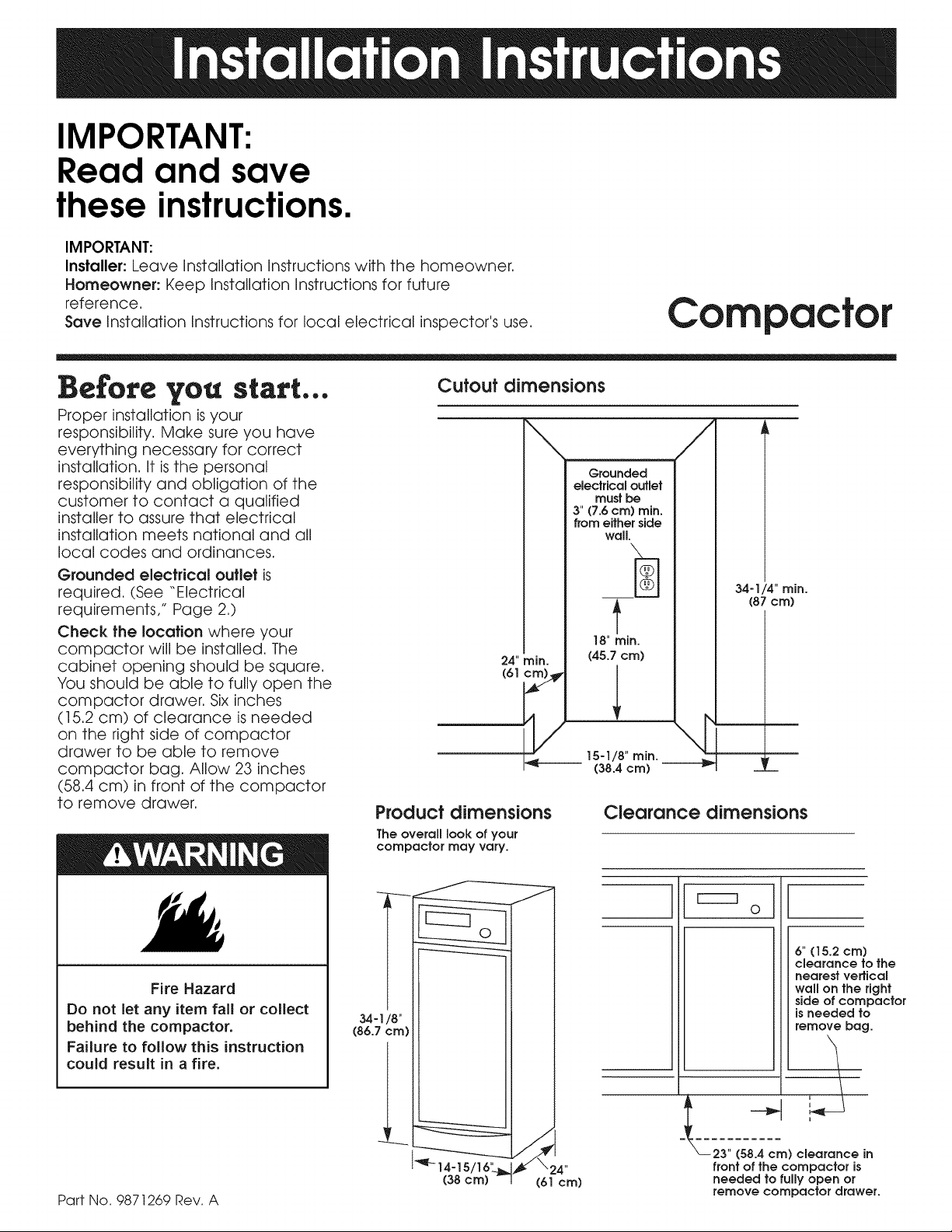
Cutout dimensions
24" rain. (45.7 era)
Product dimensions
The overall look of your
compactor may vary.
\ /
Grounded
electricaloutlet
must be
3" (7.6cm) rain.
from either side
wall.
t
18"rain.
i._b______15-1/8" rain.
(38.4 era) --
Clearance dimensions
34-1/4" min.
(87 cm)
m
Fire Hazard
Do not let any item fall or collect
behind the compactor.
Failure to follow this instruction
could result in a fire.
Part No. 9871269 Rev. A
34-I/8"
(86.7 cm)
1_q-14-15
(38cm)
(61 cm)
1I ol
23" (58.4 cm) clearance in
front of the compactor is
needed to fully open or
remove compactor drawer.
6" (15.2 cm)
clearance to the
nearest vertical
wall on the right
side of compactor
is needed to
remove bag.
Page 2
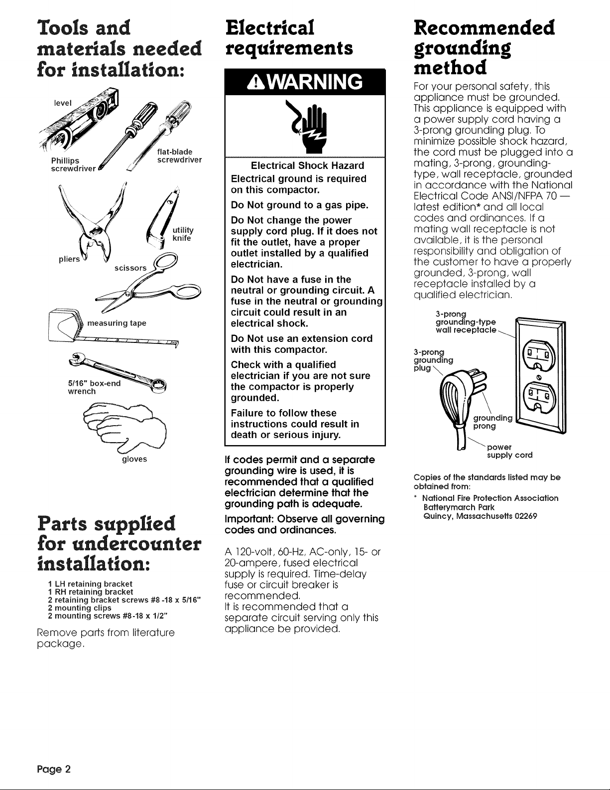
Tools and
Electrical
Recommended
mate als needed
for installation:
flat-blade
Phillips
screwdriver
gloves
screwdriver
Parts supplied
for undet¢ountet
{nstalla{iom
1 LH retaining bracket
1 RH retaining bracket
2 retaining bracket screws #8-18 x 5/16"
2 mounting clips
2 mounting screws #8-18 x 1/2"
Remove parts from literature
package.
requirements
Electrical Shock Hazard
Electrical ground is required
on this compactor.
Do Not ground to a gas pipe.
Do Not change the power
supply cord plug. If it does not
fit the outlet, have a proper
outlet installed by a qualified
electrician.
Do Not have a fuse in the
neutral or grounding circuit. A
fuse in the neutral or grounding
circuit could result in an
electrical shock.
Do Not use an extension cord
with this compactor.
Check with a qualified
electrician if you are not sure
the compactor is properly
grounded.
Failure to follow these
instructions could result in
death or serious injury.
If codes permit and a separate
grounding wire is used, it is
recommended that a qualified
electrician determine that the
grounding path is adequate.
Important: Observe all governing
codes and ordinances.
A 120-volt, 60-Hz, AC-only, 15- or
20-ampere, fused electrical
supply is required. Time-delay
fuse or circuit breaker is
recommended.
It is recommended that a
separate circuit serving only this
appliance be provided.
grounding
method
For your personal safety, this
appliance must be grounded.
This appliance is equipped with
a power supply cord having a
3-prong grounding plug. To
minimize possible shock hazard,
the cord must be plugged into a
mating, 3-prong, grounding-
type, wall receptacle, grounded
in accordance with the National
Electrical Code ANSI/NFPA 70 --
latest edition* and all local
codes and ordinances. If a
mating wall receptacle isnot
available, it is the personal
responsibility and obligation of
the customer to have a properly
grounded, 3-prong, wall
receptacle installed by a
qualified electrician.
3-prong
grounding-type
wall receptacle _
3-prong
grounding
plug \
groundinc
prong
power
supply cord
Copies of the standards listed may be
obtained from:
* National Fire Protection Association
Batterymarch Park
Quincy, Massachusetts 02269
Page 2
Page 3

Now start...
With compactor in room where it
will be installed.
Do Not grasp console to move
compactor.
Slide compactor onto
cardboard or hardboard before
moving compactor across floor
to prevent damaging floor
covering.
Do not allow the rear frame of
the compactor to touch the
floor covering when lifting or
moving compactor.
I • Remove compactor from
shipping carton. Remove all
protective packaging materials
such as tape and shipping pads.
Remove waxy residue caused
by protective shipping material
with a mild solution of liquid
household cleaner and water.
clip
cord _
• Check that power supply
cord is attached to the cord clip
on the rear of the compactor.
• Place two corner posts
from carton on floor near
compactor. Open compactor
drawer and remove any
shipping materials or other items
shipped in the drawer. Do Not
remove the compactor bag (if
installed). Grasp the handle and
raise the front of drawer until it
clears stops. Grasp sides of
drawer and lift drawer out of
compactor. Place the drawer
on the two corner posts.
leveling legs
• Place the other two corner
posts on the floor to the side of
the compactor. Grasp the sides
of the compactor cabinet and
put compactor on its side on
top of the corner posts. Remove
the shipping base from the
bottom of compactor.
cabinet
wheel _ loca.,ting stud
bracket lJ/{' _ ""
assembly_
fJ "self-tapping
screw (pivot) _i
• Freestanding installation:
Go to Step 7.
Undercounter installation:
Measure the height of your
cabinet opening. The top of the
compactor should be at least
1/8" (3 mm) from the top of the
cabinet opening.
The rear wheels are preset for a
cabinet opening height of
34-1/4" (87 cm) (Position "A').
To adjust for other cabinet
opening heights, loosen screw
just enough to clear stud from
hole in position "A'. Move the
rear wheel and stud to position
"B" or "C" as needed for your
cabinet opening measurement:
Position B: 34-1/4" to 34-7/16"'
(87 to 87.5 cm)
Position C: 34-7/16" to 34-5/8"
(87.5 to 88 cm)
Tighten screw. Repeat for other
rear wheel.
• Use pliers to lower leveling
legs away from cabinet. Adjust
legs so there will be a 1/8"
(3 mm) to 1/4" (6.4 mm) space
between the top of the
compactor and the top of the
cabinet opening. Stand the
compactor upright.
7 -
• Use pliers to lower leveling
legs away from cabinet. Place
level inside on the floor of the
cabinet. Check that the
compactor is level from front to
back and side to side. Adjust the
leveling legs until the compactor
is level.
countertop
....... " retaining
• Freestandinginstallation:
Go to Step 9.
Undercounter installation:
For model with cabinet, remove the
plastic plugs from the compactor
cabinet top. Determine if you want
the compactor frame or drawer
front flush with the cabinet front.
Using the two #8 -18 x 5/16" screws,
install the retaining brackets to
cabinet top as needed:
If the compactor frame is to be flush
with the cabinet front, place
retaining bracket screws through
\\A/' ,
If the compactor drawer front isto
be flush with the cabinet front,
place retaining bracket screws
through "C'.
If the compactor is to be midway
between "A" and "C', place
retaining bracket screws
through "B'. Page 3
bracket
Page 4

retaining
Adjusting the
Injury Hazard
When moving or lifting the
compactor, use a glove to
protect and cushion your hand.
More than one person is
recommended to lift or move
compactor because of its size
and weight. Use proper lifting
methods.
Failure to follow these
instructions could result in
injury.
lift here
.. Move the compactor
close to its final position. Plug
the power supply cord into a
properly grounded receptacle.
Freestanding installation:
Carefully move compactor into
its final position. Check that
compactor isstill level. (See Step
7, Page 3.) Go to Step 10.
mountin(
screw
Countertop mounting
retaining
bracket
mounting
clip
screw
Cabinet-front mounting
Undercounter installation:
Carefully lift the front slightly and
roll compactor into the cabinet
opening until the retaining
brackets stop the unit.
Using the two #8 -18 x 1/2" screws,
fasten the retaining brackets to
the underside of the countertop
with the mounting screws.
If brackets cannot be attached
to the underside of countertop,
attach mounting clips to
brackets. Fasten compactor to
cabinet front with mounting
screws through mounting clips.
toe plate
If the toe plate rubs the floor
covering, the toe plate
clearance may be changed as
follows:
a, Mark on each side of the toe
plate the amount of toe plate
that rubs the floor covering.
b, Remove the drawer from the
unit. (See Step 3, Page 3.)
c, Use a ruler and a pencil or
chalk to draw a line between
the marks on each side of
toe plate.
e, Use scissors or utility knife to
cut toe plate along line.
,g
f, Replace drawer. (See Step
10.) If toe plate still rubs floor
covering, repeat Steps a-f.
Page 4
0• Grasp sides of
compactor drawer and place
bottom of drawer into tracks. Lift
at the handle so the front of
drawer will go over drawer stops.
Close drawer. Check if drawer
opens freely. If the toe plate rubs
against floor, see "Adjusting the
toe plate" for further instructions.
To get the most efficient use
from your new compactor,
read your Use and Care
Guide/Operation Instructions.
Keep literature close to
compactor for easy
reference.
Page 5

Models KCCC151,
KUCC151 and
YKCCC151
A custom-made flat or raised
panel can be installed in place of
the color panel. A new Trim Kit,
(Part No. 9871381 brushed stainless
steel, 9871382 white, 9871383
black or 9871384 almond) must be
ordered. The front panel must be
removed. Follow trim kit instructions
to install your customized panel.
Paint, wallpaper or other material
can be applied to a flat panel
and installed with the new trim kit
listed above. The existing
compactor color panel and trim
cannot be customized.
Custom-made panel
dimensions
23-13/16"
(60.5cm)
_( 14-518"-_
37.2cm) I
Flat panel: A 7/32" (5.6 mm) thick
panel is required. This isthe same
thickness as a standard 1/4"
plywood or paneling.
7132"
(5.6
ram)
raised --
panel or
decorative
trim
outer--
section of
panel
5116"
(8 ram) -],
both sides
Raisedpanel:The outer section of
panel must be 7/32" (5.6 mm) thick
to fit into trim. Raised decorative
trim or raised panel sections must
be 5/16" (8 mm) from the side and
bottom edges and 25/32" (20 mm)
from the top edge of the outer
section.
14-5/8" --I_
(37.2cm)
_(8 ram)
321-1/4"
23-13/16"
(60.5cm)
5/16"
All other models
Changing color panel:
Injury Hazard
Wear gloves and handle
panel(s) carefully.
Replace handle before
operating compactor.
Failure to follow these
instructions could result in
injury.
outside front
panel
•drawer
trim
1. Remove the drawer from the
unit. (See Step 3, Page 3.)
2. Remove the screws that
attach the handle to the
drawer.
3. Remove one spacer panel.
4. Remove color panel(s) by
carefully pulling up.
5. Select the color you wish to
show and carefully push that
panel into the drawer trim.
6. Replace the spacer panels
and other color panel.
7. Attach the handle.
8. Replace the drawer. (See
Step10, Page 4.)
Installing a custom-made
panel:
Paint, wallpaper or other material
can be applied to the color
panel.
A custom-made flat or raised
panel can be installed in place
of the color panel(s) and
spacers.
Custom-made panel
dimensions
_ 14-5/8" --_
(37.2cm) /
Flat panel: A 7/32" (5.6 mm)
thick panel isrequired. This is the
same thickness as a standard
1/4" plywood or paneling.
(5!/32" ----.4_
ram)
raised--
panel or
decorative
trim
outer--
section of
panel
Raised panel: The outer section
of panel must be 7/32" (5.6 mm)
thick to fit into trim. Decorative
trim or raised panel sections
must be 5/16" (8 mm) from all
edges of outer section.
I.Follow Steps 1through 4
"Changing color panel," but
remove all the cardboard
spacers.
2. Slide customized panel into trim.
3. Reattach handle.
4. Replace the drawer. (See Step
10, Page 4.)
14-5/8"--_
_-. (37.2 cm) I
"N
"N
T
22-15/16"
(58.3cm)
-5/16" (8 ram)
all around
22-15/16"
(58.3cm)
Page 5
Page 6

Before you call
for service...
If you need
asszstance...
If your compactor does not
operate properly, check the
following before calling for
service.
If the compactor won't operate:
• Is the power supply cord
securely plugged into an
electrical outlet?
• Has the house fuse blown or
circuit breaker tripped?
• Is the drawer completely
closed?
• Is the key-knob turned all the
way to STARTposition before it
isreleased?
If compactor stops during
operation:
• Push drawer in firmly while
turning key-knob to START.
Repeat if necessary.
• Rearrange trash load -- Do
Not load rigid items at front of
drawer.
Trashnotcompacted:
• Drawer must be at least 1/3 full
to see compaction.
Not enough compaction or
force:
• Compacting works best when
only a few items are loaded.
Use the compacting cycle
frequently.
Drawer won't open:
• Drawer will open only when
ram is all the way up. To raise
the ram, push drawer in firmly
and turn key-knob to START.
Release key-knob. Open
drawer and lay items flat in
center of drawer. Start
compactor again.
• If you are using EXTRA PACK,
DENSE PACK, SOLID PACK or
COMPACT/HOLD, make sure
the rocker switch is in the
NORMAL position and the
indicator light is OFF.
Check your Use and Care Guide
for a toll-free number to call, or
call the dealer from whom you
purchased this appliance. The
dealer is listed in the Yellow
Pages of your phone directory
under "Appliances -- Household
-- Major -- Service and Repair."
When you call, you will need the
compactor model number and
serial number. Both numbers are
on the model/serial rating plate,
which can be found by pulling
out the drawer and looking on
the left-hand side of the cabinet
opening.
Part No. 9871269 Rev. A
© 1996 Printed in U.S.A.
 Loading...