

Jenn-Air JMD2124WS Technical Education


FORWARD
This Jenn-Air, Drawer Microwave Oven job aid (Part No. 8178775), provides the technician with
information on the installation, operation, and service of the Drawer Microwave Oven. It is to
be used as a training Job Aid and Service Manual. For specic information on the model being
serviced, refer to the “Use and Care Guide,” or “Wiring Diagram” provided with the microwave
oven.
The Wiring Diagrams used in this Job Aid are typical and should be used for training purposes
only. Always use the Wiring Diagram supplied with the product when servicing the unit.
GOALS AND OBJECTIVES
The goal of this Job Aid is to provide detailed information that will enable the service technician to
properly diagnose malfunctions and repair the KitchenAid Over-The-Counter Microwave Oven.
The objectives of this Job Aid are to:
• Understand and follow proper safety precautions.
• Successfully troubleshoot and diagnose malfunctions.
• Successfully perform necessary repairs.
• Successfully return the microwave to its proper operational status.
WHIRLPOOL CORPORATION assumes no responsibility for any repairs made
on our products by anyone other than Authorized Service Technicians.
Copyright © 2009, Whirlpool Corporation, Benton Harbor, MI 49022
- ii -

TABLE OF CONTENTS
Page
GENERAL .............................................................................................................................. 1-1
Safety First ......................................................................................................................... 1-1
Important Information for Service Technicians ................................................................... 1-4
Precautions To Be Observed Before And During Servicing
To Avoid Possible Exposure To Excessive Microwave Energy ........................................ 1-5
R.F. Leakage Test .............................................................................................................. 1-6
Model & Serial Number Label Location.............................................................................. 1-7
Specications ..................................................................................................................... 1-8
Jenn-Air Cooking Appliance Warranty ............................................................................. 1-10
INSTALLATION REQUIREMENTS ........................................................................................ 2-1
Product Dimensions ........................................................................................................... 2-2
THEORY OF OPERATION ..................................................................................................... 3-1
Microwave Operating Sequence ........................................................................................ 3-1
The Absolute Humidity (AH) Sensor Circuit ....................................................................... 3-3
Schematic (Off Condition) .................................................................................................. 3-5
COMPONENT ACCESS ........................................................................................................ 4-1
Component Locations ........................................................................................................ 4-1
Accessing Internal Components ........................................................................................ 4-2
Removing The Power Cord ................................................................................................ 4-4
Removing The Secondary Interlock Switch, Monitor Switch And Front
And Rear Door Switch ..................................................................................................... 4-5
Removing The Oven Lamp ................................................................................................ 4-7
Removing The Drawer Assembly ....................................................................................... 4-8
Removing The Stirrer Cover And Stirrer Fan Assemblies .................................................. 4-9
Removing The Stirrer Motor ............................................................................................. 4-10
Removing The Humidity Sensor .......................................................................................4-11
Interior Components Locations ........................................................................................ 4-12
Removing The High Voltage Capacitor And Diode .......................................................... 4-13
Removing The High Voltage Transformer ........................................................................ 4-14
Removing The Magnetron ................................................................................................ 4-15
Removing The Cooling Fan Assembly ............................................................................. 4-16
Removing The Relay, Noise Filter And Power Supply Boards ......................................... 4-17
Removing The Auto Drawer Gear .................................................................................... 4-18
Removing The Rack Gear ................................................................................................ 4-19
- iii -

Page
COMPONENT TESTING ........................................................................................................ 5-1
Microwave Oven Power Output Test .................................................................................. 5-1
Switching Power Supply (Switching Regulator) ................................................................. 5-3
DIAGNOSIS & TROUBLESHOOTING .................................................................................. 6-1
Troubleshooting ................................................................................................................. 6-1
Primary Secondary And Monitor Interlock Switch Checkout Procedures........................... 6-2
Diagnostics......................................................................................................................... 6-3
WIRING DIAGRAM ................................................................................................................ 7-1
Schematic Diagram ............................................................................................................ 7-1
- iv -
GENERAL
WARNING
WARNING
WARNING
WARNING
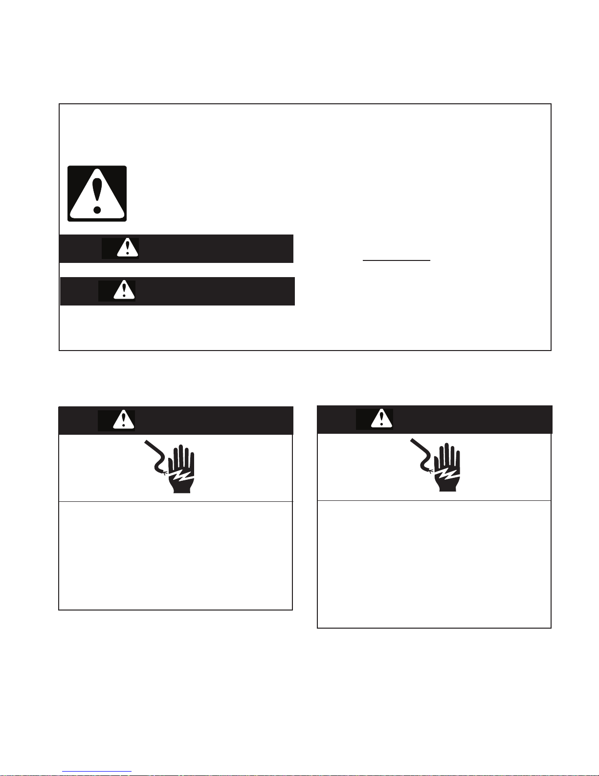
SAFETY FIRST
Your safety and the safety of others is very important.
We have provided many important safety messages in this Job Aid and on the appliance.
Always read and obey all safety messages.
This is the safety alert symbol.
This symbol alerts you to hazards that can kill or hurt you and others.
All safety messages will follow the safety alert symbol and either the word
“DANGER” or “WARNING.” These words mean:
You can be killed or seriously injured if
DANGER
you don’t immediately follow instructions.
WARNING
All safety messages will tell you what the potential hazard is, tell you how to reduce the
chance of injury, and tell you what can happen if the instructions are not followed.
ELECTRICAL POWER SUPPLY &
GROUNDING REQUIREMENTS
WARNING
Electrical Shock Hazard
Disconnect power before servicing.
Replace all parts and panels before
operating.
Failure to do so can result in death or
electrical shock.
You can be killed or seriously injured if
you don’t follow instructions.
WARNING
Electrical Shock Hazard
Plug into a grounded 3-prong outlet.
Do not remove ground prong.
Do not use an adapter.
Do not use an extension cord.
Failure to follow these instructions can
result in death, re, or electrical shock.
1-1

Before touching any oven component or wiring,
always unplug the oven from its power source
and discharge the high voltage capacitor .
Check that the unit is grounded before troubleshooting. Be careful of the high voltage circuits.
Discharge any static charge from your body by
touching ground before handling any part of
the circuitry on the control board. Electrostatic
discharge may damage the control circuit.
Do not touch oven components or wiring during operation. Attach meter leads with alligator
clips when making operational tests.
For continued protection against radiation emission, replace only with these types of switches:
Primary (Interlock) Switch: SZM-V16-FA-63
or VP-533A-OF; Secondary (Interlock) Switch:
SZM-V01-FA-32; Interlock (Monitor) Switch:
SZM-VI6-FA-62 or VP-532A-OF; Oven Lamp
Switch: SZM-V6-FA-31 or VP-331 A-OD.
It is neither necessary nor advisable to attempt
measurement of high voltage.
Attaching the adaptor ground terminal to the
wall receptacle cover screw does not ground
the appliance unless the cover screw is metal
and not insulated and the wall receptacle is
grounded through the house wiring.
The microwave oven must be grounded. In the
event of an electrical short circuit, grounding
reduces the risk of electrical shock by providing an escape wire for the electrical current.
The microwave oven is equipped with a cord
having a grounding wire with a grounding plug.
The plug must be plugged into an outlet that is
properly installed and grounded.
Consult a qualied electrician or serviceman if
the grounding instructions are not completely
understood, or if doubt exists as to whether
the microwave oven is properly grounded. Do
not use an extension cord. If the power supply
cord is too short, have a qualied electrician
or serviceman install an outlet near the microwave oven.
1-2

ELECTROSTATIC DISCHARGE
(ESD) SENSITIVE ELECTRONICS
ESD problems are present everywhere. ESD
may damage or weaken the electronic control
assembly. The new control assembly may ap-
pear to work well after repair is nished, but
failure may occur at a later date due to ESD
stress.
• Use an antistatic wrist strap. Connect the
wrist strap to a green ground connection
point or unpainted metal in the appliance;
or touch your nger repeatedly to a green
ground connection point or unpainted metal
in the appliance.
• Before removing the part from its package,
touch the antistatic bag to a green ground
connection point or unpainted metal in the
appliance.
• Avoid touching electronic parts or terminal
contacts. Handle the electronic control assembly by the edges only.
• When repackaging the failed electronic control assembly in an antistatic bag, observe
the above instructions.
1-3

IMPORTANT INFORMATION FOR SERVICE TECHNICIANS
To avoid possible exposure to microwave
radiation or energy, visually check the oven
for damage to the drawer and drawer seal
before operating any oven. Use a microwave
survey meter to check the amount of leakage
before servicing. In the event the R.F. Ieakage
2
exceeds 4 mw/cm
at 5 cm, appropriate repair
must be made before continuing to service the
unit. Check interlock function by operating the
drawer latch. The oven cook cycle should cut
off before the drawer can be opened.
The drawer and latching assembly contains the
radio frequency energy within the oven. The
drawer is protected by three safety interlock
switches. Do not attempt to defeat them.
Under no circumstances should you try to
operate the oven with the drawer open.
• Proper operation of microwave ovens
requires that the magnetron be properly
assembled to the waveguide and cavity.
Never operate the magnetron unless it is
properly installed.
• Be sure the “RF” seal is not damaged and
is assembled around the magnetron dome
properly when installing the magnetron.
• Routine service safety procedures should
be exercised at all times.
• Untrained personnel should not attempt
service without a thorough review of test
procedures and safety information contained in this Job Aid.
Jenn-Air microwave ovens have a monitoring
system designed to assure proper operation
of the safety interlock systems.
The monitor switch will immediately cause the
oven fuse to blow if the drawer is opened and
the primary door interlock switch and/or the
secondary interlock switch contacts fail in a
closed position.
NOTE: Replace a blown fuse with a 20 ampere class H fuse only.
Test the upper and lower door interlock switches, cook relay, and monitor switch (middle
switch) for proper operation as described in the
component test procedures, before replacing
the blown oven fuse.
Do not attempt to repair sticking contacts
of any interlock switch, safety switch, or
Cook (Latch) relay. The components must
be replaced.
Any indication of sticking contacts during
component tests requires replacement of that
component to assure reliability of the safety
interlock system.
If the fuse is blown, the Monitor switch,
and the Primary, and Secondary interlock
switches must be replaced. Be sure they
are properly connected.
1-4

PRECAUTIONS TO BE OBSERVED BEFORE AND DURING
SERVICING TO AVOID POSSIBLE EXPOSURE
TO EXCESSIVE MICROWAVE ENERGY
A. Do not operate or allow the oven to be
operated with the drawer open.
B. Make the following safety checks on all
ovens to be serviced before activating the
magnetron or other microwave source, and
make repairs as necessary:
1) Interlock Operation
2) Proper Drawer Closing
3) Seal and Sealing Surfaces (Arcing,
Wear, and Other Damage)
4) Damage to or Loosening of Hinges and
Latches
5) Evidence of Dropping or Abuse
C. Before turning on the microwave power
for any service test or inspection within the
microwave generating components, check
the magnetron, wave guide or transmission line, and cavity for proper alignment,
integrity, and connections.
D. Any defective or misadjusted components
in the interlock, monitor, drawer seal, and
microwave generation and transmission
systems shall be repaired, replaced, or
adjusted, using procedures described in
this Job Aid, before the oven is released
to the owner.
E. A microwave leakage check to verify
compliance with the Federal Performance
Standard should be performed on each
oven prior to release to the owner.
F. Do not attempt to operate the oven if the
drawer glass is broken.
1-5

R.F. LEAKAGE TEST
EQUIPMENT
• Electromagnetic energy leakage monitor
(NARDA 8100B, HOLADAY H 1501 ).
• 275 ±15 ML glass beaker.
TEST
On every service call, checks for microwave
energy emission must be made according to
the following manner.
1. Remove the cooking rack from the
oven cavity, if the microwave oven is so
equipped.
2. Place a 275 ±15 ML (9.3 oz.) glass of water
in the center of the oven bottom.
3. Select "HIGH" cook power, turn the microwave oven on, and test for R.F. Ieakage
at the following locations:
a) Around the cabinet at the front.
b) Around the door/drawer.
c) Across the console panel.
d) Horizontally across the door/drawer.
e) Vertically across the door/drawer.
f) Diagonally across the door/drawer.
g) Across the air vents.
h) Across the rear air vent.
i) All lockseams.
j) Weld at bottom.
k) Bottom plate.
I) Oven feet.
4. The scan speed is one inch per second.
When checking for R.F. Ieakage, use an approved R.F. measuring device to assure less
than 4 mw/cm
a maximum scan rate of 2.54 cm/second, in
compliance with U.S. Government Department
of Health, Education and Welfare 21CFR1030,
Performance Standard for Microwave Ovens.
2
emission at 5 cm distance with
NOTE: Enter leakage readings in space BEFORE and AFTER on the service document.
All microwave ovens exceeding the emission
2
level of 4 mw/cm
must be reported to Dept.
of Service for Microwave Ovens immediately
and the owner should be told not to use the
micro- wave oven until it has been repaired
completely.
If a microwave oven is found to operate with
the door open, report to Dept. of Service, the
manufacturer and CDRH* immediately. Also
tell the owner not to use the oven.
The monitor switch acts as the nal safety
switch protecting the customer from microwave
radiation. If the monitor switch operated to blow
the fuse when the interlocks failed, you must
replace all interlock switches with new ones,
because the contacts of those interlock switches
may be melted and welded together.
If safety interlock/monitor switch replacement,
or adjustment, is required, you must reconnect
the circuit, and perform a continuity check on
the monitor circuit.
All repairs must be performed in such a manner that microwave energy emissions are
minimal.
Address for CDRH is:
Ofce of Compliance (HFZ-312) Center for
Devices and Radiological Health
1390 Piccard Drive
Rockville, MD 20850
* CDRH: Center for Devices and Radiological
A properly operating drawer and seal assembly
will normally register small emissions, but they
must be no greater than 4 mw/cm
measurement uncertainty.
2
to allow for
1-6
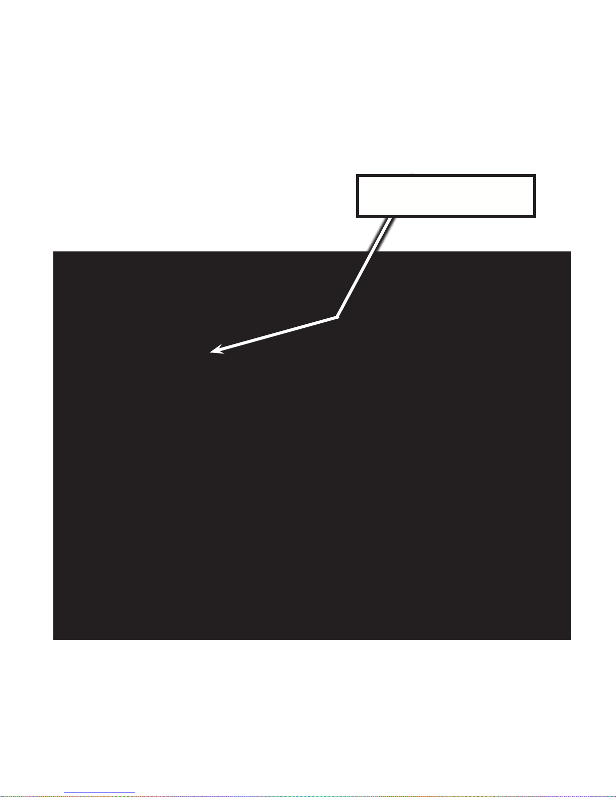
MODEL & SERIAL NUMBER LABEL LOCATION
The Model/Serial Number label location is shown below.
Model & Serial
Number Label Location
Right Side Wall Behind the Drawer
1-7

SPECIFICATIONS
Setup/Help Pad, Control Lock Pad, Sensor Popcorn Pad, Keep Warm Pad, Sensor
Clock Pad, Defrost Pad, Sensor Reheat Pad, Reheat Pad, Open Pad, Close Pad,
START/Add 1 Minute Pad, Stop/Clear Pad, Power Level Pad, Timer Clock Pad.
1-8
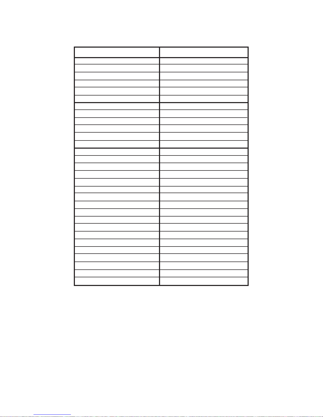
SPECIFICATIONS
Model JMD2124WS
Brand Jenn-Air
Platform Built-in Microwave Drawer
Size-Conguration 24” 1.0 Cu. Ft.
Feature Level Series Sensor
Fuel Type Electric
Color Stainless
Dimensions
Overall Height (in) 15 13/32”
Overall Width (in) 23 7/8”
Overall Depth (in) 26 3/16”
Door Swing (in) Drawer Open 15”
Weight Crated – lb 103
Electrical Specications
Voltage 120
Phase Single
Frequency 60
Circuit Amps @ 120VAC 15
Power Cord Yes 3 Ft.
UL Approved Yes
Domestic Use Only Yes
Residential Use Only Yes
CUL Approved Yes
Window Material Glass
Handle Material N/A Power Open/Close
Cooking Power Wattage 950
Interior Light Yes - “On” when open
Light Type Incandescent
Light Wattage 10
Magnetron Yes
Levels 10
103
120
60
15
950
10
10
1-9

JENN-AIR® COOKING APPLIANCE WARRANTY
LIMITED WARRANTY
For one year from the date of purchase, when this major appliance is operated and maintained according to instructions attached to or
furnished with the product, Jenn-Air brand of Whirlpool Corporation or Whirlpool Canada LP (hereafter “Jenn-Air”) will pay for factory
specified parts and repair labor to correct defects in materials or workmanship. Service must be provided by a Jenn-Air designated
service company. This limited warranty is valid only in the United States or Canada and applies only when the major appliance is used
in the country in which it was purchased. Outside the 50 United States and Canada, this limited warranty does not apply. Proof of
original purchase date is required to obtain service under this limited warranty.
SECOND THROUGH FIFTH YEAR LIMITED WARRANTY ON CERTAIN COMPONENT PARTS
In the second through fifth years from the date of purchase, when this appliance is operated and maintained according to instructions
attached to or furnished with the product, Jenn-Air will pay for factory specified parts for the following components (if applicable to the
product) if defective in materials or workmanship:
ITEMS EXCLUDED FROM WARRANTY
This limited warranty does not cover:
1. Service calls to correct the installation of your major appliance, to instruct you on how to use your major appliance, to replace or
repair house fuses, or to correct house wiring or plumbing.
2. Service calls to repair or replace appliance light bulbs, air filters or water filters. Consumable parts are excluded from warranty
coverage.
3. Repairs when your major appliance is used for other than normal, single-family household use or when it is used in a manner that is
contrary to published user or operator instructions and/or installation instructions.
4. Damage resulting from accident, alteration, misuse, abuse, fire, flood, acts of God, improper installation, installation not in
accordance with electrical or plumbing codes, or use of consumables or cleaning products not approved by Jenn-Air.
5. Cosmetic damage, including scratches, dents, chips or other damage to the finish of your major appliance, unless such damage
results from defects in materials or workmanship and is reported to Jenn-Air within 30 days from the date of purchase.
6. Any food loss due to refrigerator or freezer product failures.
7. Costs associated with the removal from your home of your major appliance for repairs. This major appliance is designed to be
repaired in the home and only in-home service is covered by this warranty.
8. Repairs to parts or systems resulting from unauthorized modifications made to the appliance.
9. Expenses for travel and transportation for product service if your major appliance is located in a remote area where service by an
authorized Jenn-Air servicer is not available.
10. The removal and reinstallation of your major appliance if it is installed in an inaccessible location or is not installed in accordance
with published installation instructions.
11. Major appliances with original model/serial numbers that have been removed, altered or cannot be easily determined. This warranty
is void if the factory applied serial number has been altered or removed from your major appliance.
The cost of repair or replacement under these excluded circumstances shall be borne by the customer.
DISCLAIMER OF IMPLIED WARRANTIES; LIMITATION OF REMEDIES
CUSTOMER'S SOLE AND EXCLUSIVE REMEDY UNDER THIS LIMITED WARRANTY SHALL BE PRODUCT REPAIR AS PROVIDED
HEREIN. IMPLIED WARRANTIES, INCLUDING WARRANTIES OF MERCHANTABILITY OR FITNESS FOR A PARTICULAR PURPOSE,
ARE LIMITED TO ONE YEAR OR THE SHORTEST PERIOD ALLOWED BY LAW. JENN-AIR SHALL NOT BE LIABLE FOR INCIDENTAL
OR CONSEQUENTIAL DAMAGES. SOME STATES AND PROVINCES DO NOT ALLOW THE EXCLUSION OR LIMITATION OF
INCIDENTAL OR CONSEQUENTIAL DAMAGES, OR LIMITATIONS ON THE DURATION OF IMPLIED WARRANTIES OF
MERCHANTABILITY OR FITNESS, SO THESE EXCLUSIONS OR LIMITATIONS MAY NOT APPLY TO YOU. THIS WARRANTY GIVES
YOU SPECIFIC LEGAL RIGHTS, AND YOU MAY ALSO HAVE OTHER RIGHTS WHICH VARY FROM STATE TO STATE OR PROVINCE
TO PROVINCE.
If outside the 50 United States and Canada, contact your authorized Jenn-Air dealer to determine if another warranty applies.
If you need service, first see the “Troubleshooting” section of the Use & Care Guide. After checking “Troubleshooting,” you may find
additional help by checking the “Assistance or Service” section or by calling Jenn-Air. In the U.S.A., call 1-800-688-1100. In Canada,
call 1-800-807-6777.
9/07
Keep this book and your sales slip together for future
reference. You must provide proof of purchase or installation
date for in-warranty service.
Write down the following information about your major appliance
to better help you obtain assistance or service if you ever need it.
You will need to know your complete model number and serial
number. You can find this information on the model and serial
number label located on the product.
Dealer name____________________________________________________
Address ________________________________________________________
Phone number__________________________________________________
Model number __________________________________________________
Serial number __________________________________________________
Purchase date __________________________________________________
� Electric element
� Touch Pad and microprocessor
� Glass ceramic cooktop: if due to thermal breakage
� Electronic controls
� Magnetron tube
� Sealed gas burners
JENN-AIR® COOKING APPLIANCE WARRANTY
1-10
INSTALLATION REQUIREMENTS
INSTALLATION REQUIREMENTS
Tools and Parts
Tools Needed
Gather the required tools and part s before starting installation.
Read and follow the instructio ns provided with any tools
listed here.
Parts Supplied
The microwave drawer is preassembled.
1" (2.5 cm) mounting screws (4)
Materials needed
6" (15.2 cm) Anti-Tip block (installer to provide)
Location Requirements
The microwave drawer may be located in a cabinet or below the
counter, and/or below a built-in oven. Check the opening where
the microwave drawer will be inst alled. The location must provide:
Wood cabinetry.
Cutout opening that is plu mb and square. See “Minimum
Cutout Dimensions” in “Minimum Dimensions” section.
Cutout floor that is solid, level and flush with bottom of
cabinet cutout.
Support for weight of at least 100 lbs (45.4 kg), which includes
microwave oven and items placed inside.
Grounded electrical outlet. See “Electrical Requirements”
section.
Minimum installation clearances for installation location. See
“Minimum Dimensions” section.
Complete enclosure around the recessed portion of the
microwave drawer.
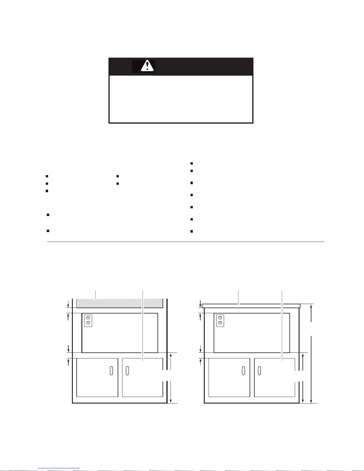
Minimum Dimensions
Minimum Installation Clearances
For proper installation, the following minimum clearances must exist above and below the cutout opening.
Measuring tape
Pencil
No. 2 Phillips screwdriver
Drill
1/16" (2 mm) drill bit
2" (5.1 cm)
2" (5.1 cm)
A B C B
19"
(48.3 cm)
2" (5.1 cm)
2" (5.1 cm)
36"
(91.4 cm)
19"
(48.3 cm)
A. Upper oven
B. Lower cabinet
C. Counter
Excessive Weight Hazard
Use two or more people to move
and install the microwave oven.
Failure to do so can result in back or
other injury.
WARNING
WARNING
WARNING
Excessive Weight Hazard
Use two or more people to move and
install the microwave oven.
Failure to do so can result in back or
other injury.
2-1
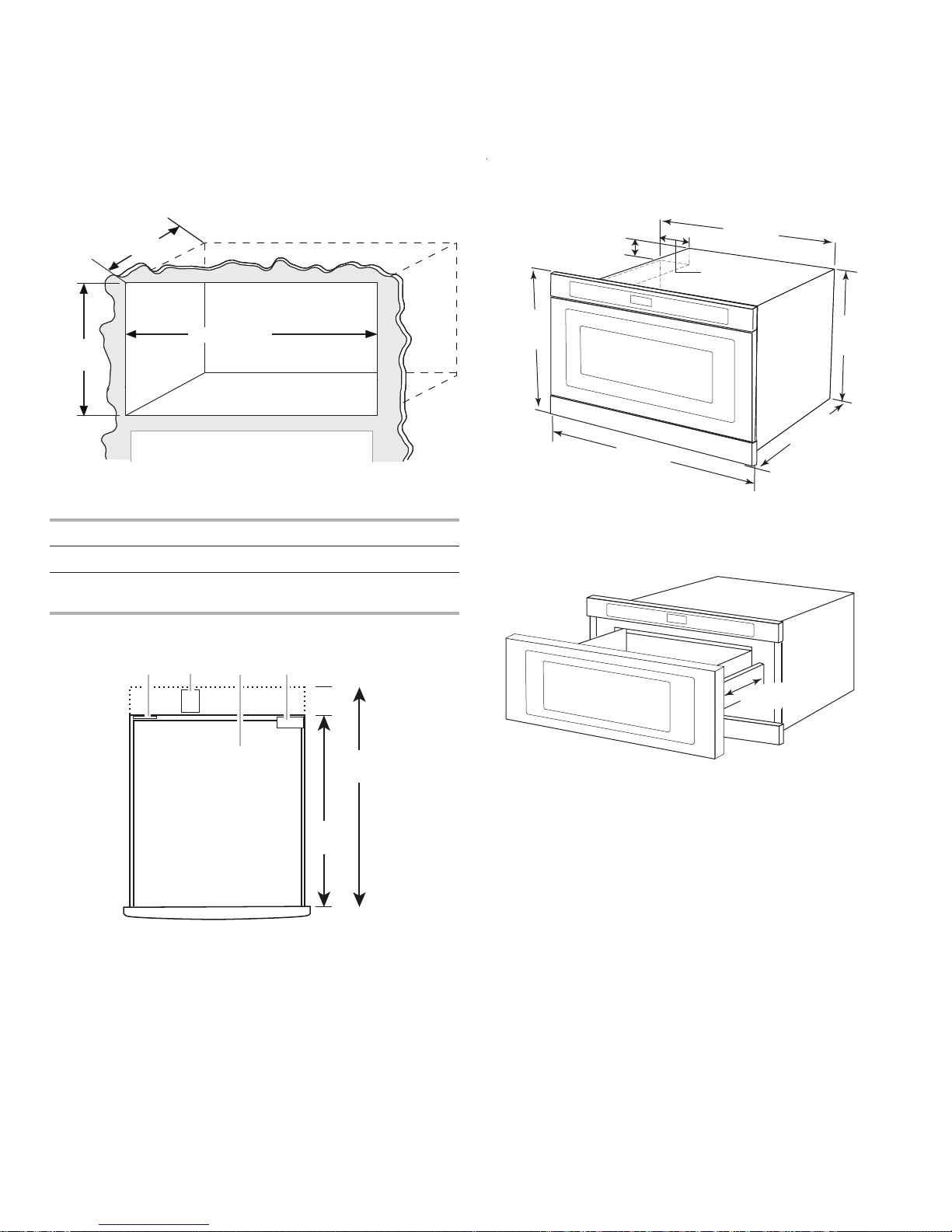
Minimum Cutout Dimensions
*With flush receptacle.
**With non-flush receptacle.
Cutout Top View
Product Dimensions
*Measurements include front facing of microwave drawer.
The drawer opens 15" (38.1 cm).
Width 22¹⁄₈" (59.7 cm)
Height 14¹³⁄₁₆" (37.6 cm) for all installations
Depth 23¹⁄₂" (59.7 cm) with flush receptacle;
28" (71.1 cm) with non-flush receptacle
A. Flush receptacle located in upper left corner only
B. Non-flush receptacle
C. Microwave drawer
D. Anti-tip block located in upper right corner only
14¹³⁄₁₆"
(37.6 cm)
23
¹⁄₂" (59.72 cm)*
28" (71.1 cm)**
22¹⁄₈" (56.2 cm)
23¹⁄₂"
(59.7 cm)
28"
(71.1 cm)
A B C D
1²³⁄₃₂" (4.4 cm)
4¹¹⁄₁₆" (11.9 cm)
15¹³⁄₃₂"
(39.1 cm)
14
¹⁹⁄₃₂"
(37.1 cm)
21
¹⁹⁄₃₂"
(54.9 cm)
23
²⁵⁄₃₂"
(60.4 cm)*
24
⁹⁄₁₆"
(62.4 cm)*
15" (38.1 cm)
PRODUCT DIMENSIONS
2-2
 Loading...