

Jenn-Air JMD2124W Detailed Planning Dimensions
JENN-AIR® DETAILED PLANNING DIMENSIONS
N
O
P
M
G
Back of
Cabinet
A
N
O
P
M
G
C G
B
D
E
F
Back of
Cabinet
Power Supply Location
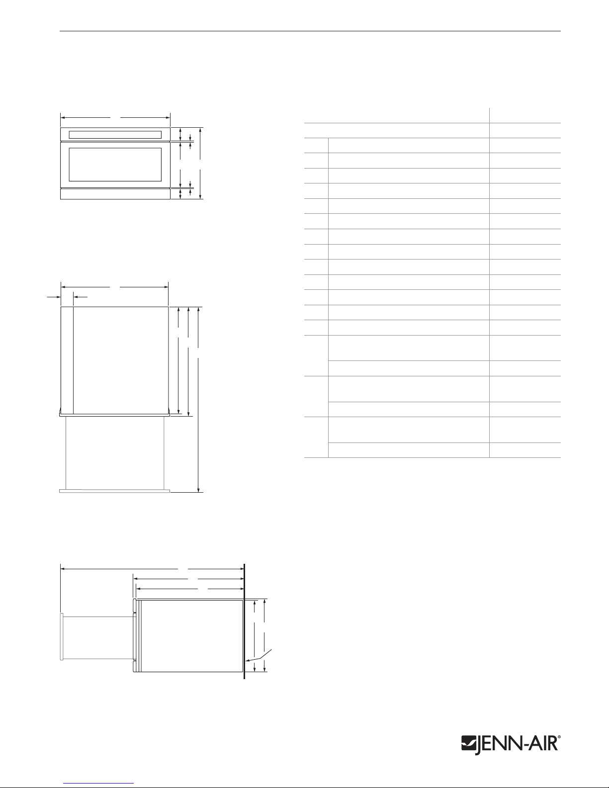
uNDER cOuNTER MIcROwAvE OvEN wITh DRAwER DESIGN
JMD2124W – 233⁄4" x 153⁄8" x 241⁄2"
PRODucT DIMENSIONS
1 of 2
FRONT VIEW
I
TOP VIEW
A
B
E
C G
F
D
H
J
K
L
MODEL # JMD2124W
in cm
3
Overall width 23
A
Height of control panel 2
B
Height of drawer 10
C
Height of trim 2 5.1
D
Space between control panel and drawer
E
Space between drawer and trim
F
Overall height 15
G
Recessed width 21
H
Width of conduit channel 4
I
Depth without drawer 23
J
Depth with drawer 24
K
Depth with drawer fully open 39
L
Recessed height 14
M
Depth with drawer fully open
Flush receptacle
N
⁄4 60.4
1
⁄2 6.2
1
⁄2 26.6
1
⁄8 0.4
1
⁄4 0.5
3
⁄8 39.1
5
⁄8 54.9
5
⁄8 11.9
1
⁄2 59.7
1
⁄2 62.4
1
⁄2 100.5
5
⁄8 37.1
1
39
⁄2
100.5
Non-flush receptacle 44 111.9
62.4
59.7
Depth with drawer
Flush receptacle
O
P
Non-flush receptacle 29 73.8
Depth without drawer
Flush receptacle
Non-flush receptacle 28 71.1
24
23
1
⁄2
1
⁄2
N
O
P
SIDE VIEW
Product dimension, cutout and installation specifications are provided for planning purposes only. Before installing
any product, be sure to verify cutout dimensions and electrical/gas connections as actual product dimensions may vary.
M
G
Back of
Cabinet
JRC120058A 07/2012
JENN-AIR® DETAILED PLANNING DIMENSIONS
E
N
O
P
M
G
Back of
Cabinet
E
A
B
e
C
D
2 of 2
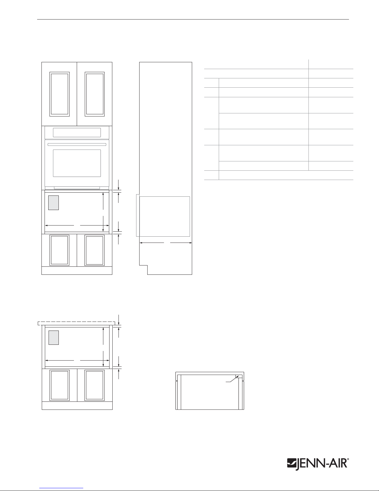
uNDER cOuNTER MIcROwAvE OvEN wITh DRAwER DESIGN
JMD2124W – 233⁄4" x 153⁄8" x 241⁄2"
OPENING/cLEARANcE DIMENSIONS
MODEL # JMD2124W
in cm
1
Width of cutout 22
A
Height of cutout 14
B
Top of cutout to bottom
of oven (min.)
C
Top of cutout to bottom
of countertop (min.)
Bottom of cutout to top
D
of cabinet door (min.)
Depth of cutout (min.)
with flush receptacle
E
with non-flush receptacle 28 71.1
e
Recommended electrical connection location
C
e
B
D
A
ELECTRICAL REQUIREMENTS
120 volt, 60 Hz, AC only, 15- or 20-amp fused, grounded circuit
is required. A time-delay fuse or dedicated circuit is recommended.
Do not use an extension cord.
LOCATION REQUIREMENTS
Support structure must be able to support 100 lb (45.4 kg) including
microwave oven and contents.
⁄8 56.2
7
⁄8 37.6
2 5.1
2 5.1
2 5.1
1
23
⁄2
59.7
FRONT VIEW – INSTALLATION UNDER
SINGLE OVEN
C
e
B
D
A
FRONT VIEW – INSTALLATION UNDER
COUNTERTOP
E
SIDE VIEW
Power Supply Location
BACK VIEW
Product dimension, cutout and installation specifications are provided for planning purposes only. Before installing
any product, be sure to verify cutout dimensions and electrical/gas connections as actual product dimensions may vary.
JRC120058A 07/2012
 Loading...