

Jenn-Air JMC8127DD, JMC8130DDQ, JJW9530D, JJW9527D, JJW7530DD Installation Instructions Manual
...
INSTALLATION
INSTRUCTIONS
Built-In 27²²²² &30²²²²
Microwave Ovens
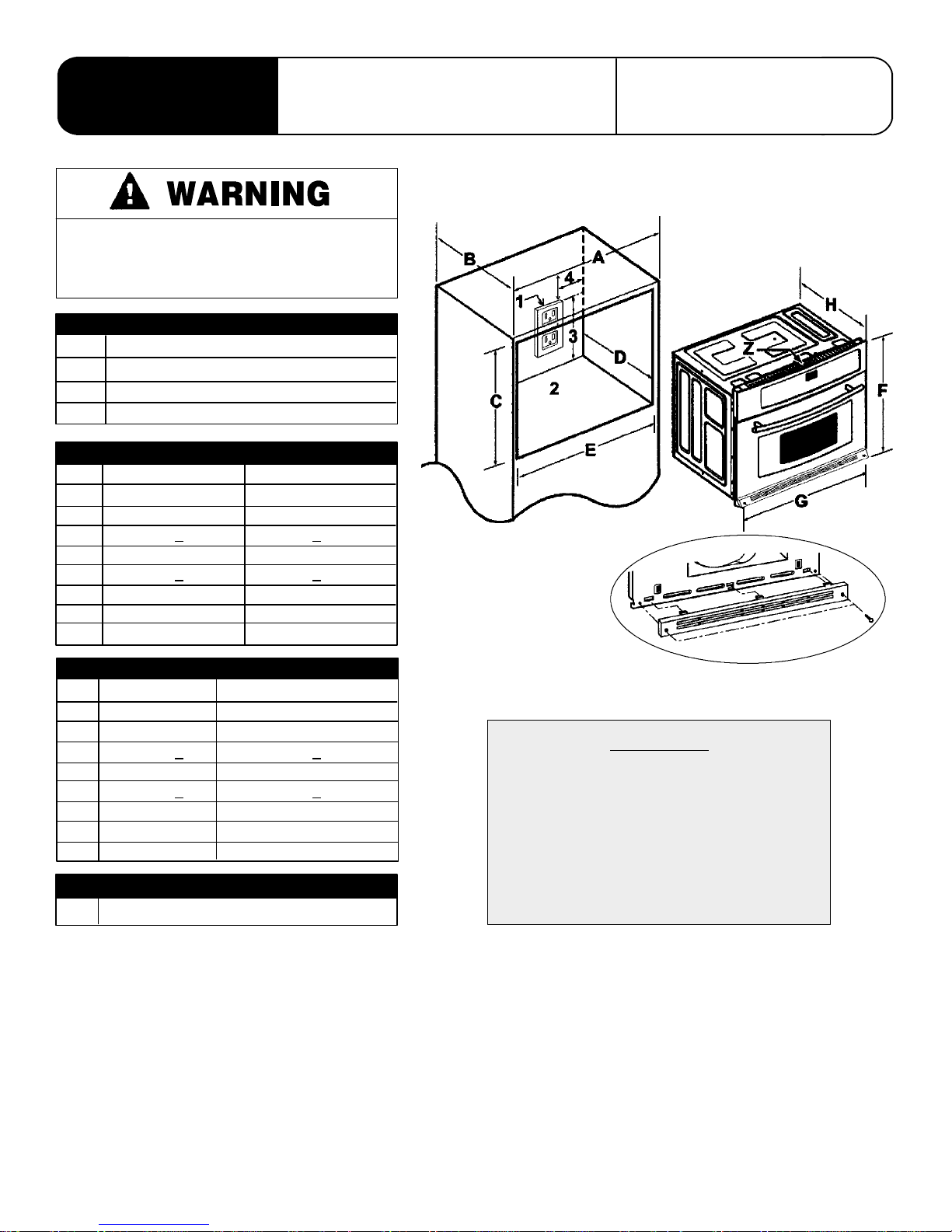
Improper installation of the grounding
circuit can result in a risk of electric
shock.
27² &30² MICROWAVE OVEN DESCRIPTION
1 Properly Polarized and Grounding Outlet.
25/8² Plywood Floor (Must Support 100 lbs.)
3 About 15-7/8 Inches
4 About 1-3/8 Inches
27² MICROWAVE OVEN DIMENSIONS
inches Centimeters
A 27 MIN 68.58 MIN
B 24 MIN 60.96 MIN
C22-5/8+
D 24 MIN 60.96MIN
E25-1/2+
F 23-7/16 59.69
G 26-3/4 67.95
H 20-3/16 51.27
1/16 57.47 + 0.16
1/16 64.77 + 0.16
403 WEST FOURTH STREET, NORTH
NEWTON, IA 50208
MICROWAVE OVEN CUTOUT
Bottom Grill
30² MICROWAVE OVEN DIMENSIONS
inches Centimeters
A 30MIN 76.2MIN
B 24 MIN 60.96 MIN
C22-5/8+
D 24 MIN 60.96MIN
E28-1/2+
F 23-7/16 59.69
G 29-3/4 75.56
H 20-3/16 51.27
Z Do not block airintake slots alongtop ofoven.
1/16 57.47 + 0.16
1/16 72.39 + 0.16
NOTES
CAUTION
For European stylecabinets (flush front)
the required clearance for operation of
the oven door is minimum spacing of
7/8² between the cutout and the door,
hinge or drawer of the cabinet. Some
built-in cabinets may not be wide
enough, due to their construction, to
allow this installation.
3828W5U0230
8101P504-60
(05-03-02)
INSTALLATION
1. Cut hole in cabinet to mount Microwave oven. Cutout in
cabinet should be level and straight.
NOTE: There are no provisions to level the unit after it
is installed. An oven that is not level could cause poor
cooking results.
2. Install plywood floor as shown above.
3. Attach unit to the cabinet with 4 long oval head screws
supplied inside of envelope containing these
instructions. Pre-drill 4 holes in cabinet for attachment
screws using 1/16² drill. Oven mounting holes are
provided in side trim.
4. Attach the bottom grill, found in the upper packing
materials, to the front plate with the 2 short truss head
screws supplied in the envelope packaged with the
bottom grill.
5. See Owner’s Manual for operating instructions.
NOTES
S Do not build in above gas wall ovens due to placement
of gas wall oven vent.
Electrical rating of this oven:
S 120 VAC @ 60 Hz.
S 13 A / 1000 W
S You need a DEDICATED 120 VAC, 60 Hz, 15 A or 20
A, fused electrical supply (located in the cabinet with
the microwave as close as possible to the microwave)
serving only the microwave.
S Check with a qualified electrician if you are not sure
whether the oven is properly grounded or if you do not
completely understand the grounding instructions.
S Do not use a fuse in the neutral or grounding circuit.
S Save these instructions for the local electrical
inspector’s use.
S If there is an electrical short circuit, grounding reduces
the risk of electrical shock by providing an escape wire
for the electric current. This appliance is equipped with
a cord having a grounding wire with a grounding plug.
S Place the plug into a properly installed and grounded
outlet.
S Maytag does not recommend use of an extension
cord.
S Keep the power cord dry and do not pinch or crush it.
S Do not, under any circumstances, remove the power
supply cord grounding prong!
S This appliance MUST
be grounded!
SERVICE
Interrupt the sourceof electricitytotheunitwhenattempting
to repair or service the oven. Failure to do this could result
in a dangerous or even fatal shock.
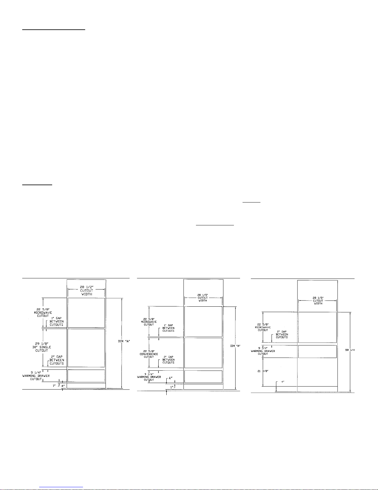
Dim “A” = With Warming Drawer = 69²
Dim “A” = Without Warming Drawer = 59¼²
Unit approved for use over the following wall ovens:
JJW9530D JJW9527D JJW7530DD
JJW8530D JJW8527D JWD7030CDX
Dim “A” = With Warming Drawer = 62½²
Dim “A” = Without Warming Drawer = 59¼²
2
SAME FOR BOTH WITH OR WITHOUT
WARMING DRAWER
 Loading...