

JennAir JJW2427DB, JJW2427DS, JJW2827DS, JJW2427IM, JJW2427IL Flush Installation Guide
...
INSTALLATION INSTRUCTIONS 27" (68.6CM)
AND 30" (76.2 CM) ELECTRIC SINGLE
AND DOUBLE BUILT-IN OVEN FLUSH
INSTALLATION KIT
INSTRUCTIONS D’INSTALLATION ENSEMBLE
D’INSTALLATION EN AFFLEUREMENT POUR
FOUR ÉLECTRIQUE ENCASTRÉ SIMPLE ET
DOUBLE DE 27" (68,6 CM) ET 30" (76,2 CM)
27" (68.6 cm) Flush Installation Kits
Ensembles d'installation en affleurement de 27" (68,6 cm)
Stainless Steel/ Acier
inoxydable,
RISETM/NOIR
Kit PN/ Ensemble référence:
W11357761
TM
Model#
Modèle n°
Black
Noir
Kit PN/ Ensemble référence:
W10791232
Stainless Steel
Acier inoxydable
Kit PN/ Ensemble référence:
W10791228
JJW2427DB, JJW2827DB
JJW2427DS, JJW2827DS,
JJW2727DS
JJW2427IM, JJW2427IL,
JJW2827IM, JJW2827IL
Model#
Modèle n°
JJW2430DS, JJW2430DP,
JJW2830DS, JJW2830DP,
JJW2730DS
JJW2430DB, JJW2830DB
JJW2430IM, JJW2430IL,
JJW2830IM, JJW2830IL
JJW3430DS, JJW3430DP,
JJW3830DS, JJW3830DP
JJW3430IM, JJW3430IL,
JJW3830IM, JJW3830IL
** * *
* ** *
* * **
30" (76.2 cm) Flush Installation Kits
Ensembles d'installation en affleurement de 30" (76,2 cm)
Kit PN
Ensemble
référence:
W10791233
Black
Noir
Kit PN
Ensemble
référence:
W10837578
Stainless Steel
Acier inoxydable
Kit PN
Ensemble
référence:
W10791229
Kit PN
Ensemble
référence:
W10837579
* ** *
** * *
* * **
* ** *
* * **
Stainless Steel/ Acier
inoxydable,
RISETM/NOIR
Kit PN
Ensemble
référence:
W11357756
TM
Kit PN
Ensemble
référence:
W11357769
JJW3430DB, JJW3830DB
Approved for use.
*
Recommended color and approved for use.
**
Approuvé pour l’utilisation.
*
Couleur recommandée et approuvé pour l’utilisation.
**
IMPORTANT:
Save for local electrical inspector’s use.
IMPORTANT:
À conserver pour consultation par l’inspecteur local des installations électriques.
W11356314A
06-May-2019 13:38:41 EDT | RELEASED
** * *
In some European factories the letter "W" of the part code mentioned herein will be automatically
replaced by the number "4000" (e.g. "W12345678" becomes "400012345678")
Table of Contents/Table des matières
BUILT-IN OVEN SAFETY ................................................................ 2
INSTALLATION REQUIREMENTS .................................................2
Tools and Parts .............................................................................2
Location Requirements ................................................................3
INSTALLATION INSTRUCTIONS ...................................................5
Prepare Built-In Oven ...................................................................5
Remove Oven Door(s) ..................................................................5
Replace Oven Door(s) ..................................................................6
Positioning Oven Feet .................................................................7
Replace Plastic Spacers ..............................................................8
Install Oven ...................................................................................9
Install Deector Kit Bracket .........................................................9
Complete Installation .................................................................10
BUILT-IN OVEN SAFETY
SÉCURITÉ DU FOUR ENCASTRÉ ..............................................11
EXIGENCES D’INSTALLATION ...................................................12
Outillage et pièces ......................................................................12
Exigences d’emplacement .........................................................12
INSTRUCTIONS D’INSTALLATION .............................................15
Préparation du four encastré .....................................................15
Dépose de la/des porte(s) du four .............................................15
Réinstallation de la/des porte(s) du four ....................................16
Positionnement des pieds du four .............................................17
Remplacement des cales d’espacement en plastique .............18
Installation du four ......................................................................19
Installation du support de la trousse du déecteur ...................19
Achever l’installation ..................................................................20
INSTALLATION REQUIREMENTS
Tools and Parts
Gather the required tools and parts before starting installation.
Read and follow the instructions provided.
Tools Needed
■ Phillips screwdriver
■ Measuring tape
■ Drill (for wall cabinet installations)
■ 1/8" (3.1 mm) drill bit (for wall cabinet installations)
■ Level
■ Flat-blade screwdriver
2
06-May-2019 13:38:41 EDT | RELEASED
Parts Supplied With Your Built-In Oven
■ #8-14 x 1" (2.5 cm) screws - (2) single ovens, (4) double
ovens included with built-in oven
■ (2) #8-18 x 3/8" (9.5 mm) screws - bottom vent included with
built-in oven
■ (4) #8-18 x 3/8" (9.5 mm) screws - included with built-in oven
■ Bottom vent included with built-in oven
■ (2) Feet double oven included with built-in oven
■ (2) Front feet double oven included with built-in oven
In some European factories the letter "W" of the part code mentioned herein will be automatically
replaced by the number "4000" (e.g. "W12345678" becomes "400012345678")
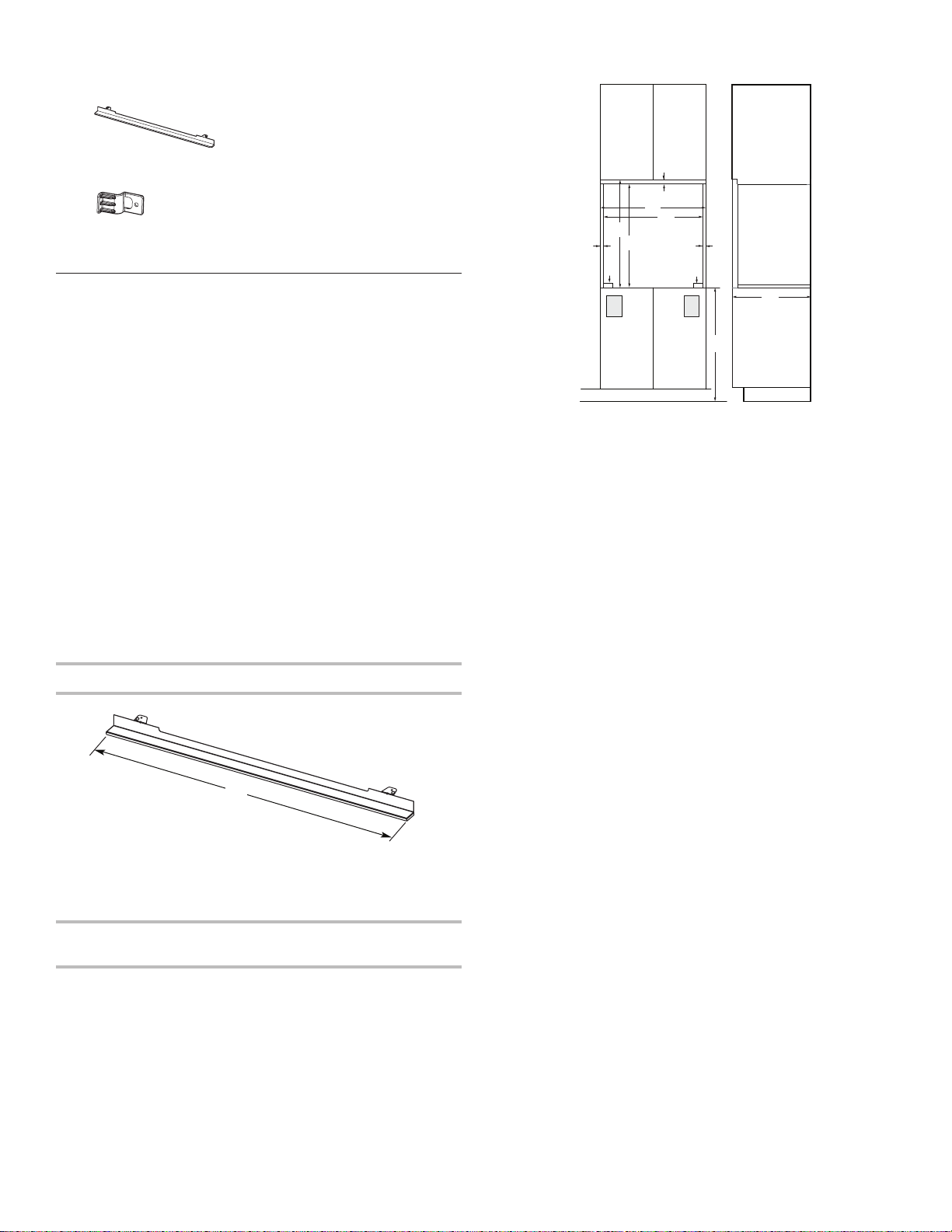
Parts Supplied
■ Deector bracket
Single Ovens Installed in Cabinet - Flush Installation
■ Plastic spacers - (4) single ovens, (6) double ovens
■ #8-18 x 1/4" (6.3 mm) screws - (2) for 27" (68.6 cm) models;
(4) for 30" (76.2 cm) models
Location Requirements
IMPORTANT: Observe all governing codes and ordinances.
NOTE: Refer to the following “Location Requirements” and the
“Location Requirements” section of the Installation Instructions
provided with your built-in oven.
■ Cabinet opening dimensions that are shown must be used.
Given dimensions provide minimum clearance with oven.
■ Recessed installation area must provide complete enclosure
around the recessed portion of the oven.
■ Oven support surface must be solid, level, and ush with
bottom of the cabinet cutout.
■ Floor must be able to support a single oven weight of
180 lbs (82 kg).
■ Floor must be able to support a double oven weight of
357 lbs (162 kg)
IMPORTANT: To avoid damage to your cabinets, check with
your builder or cabinet supplier to make sure that the materials
used will not discolor, delaminate, or sustain other damage. This
oven has been designed in accordance with the requirements
of UL and CSA International and complies with the maximum
allowable wood cabinet temperatures of 194°F (90°C).
Deflector Bracket Dimensions
A
B
C
D
E
F
G
H
Front View Side View
27" (68.6 cm) Models
A. 3/4" (19 mm) top cleat*
B. 271/4" (69.2 cm) minimum width
of flush inset cutout
C. 257/8" (65.7 cm) minimum width
of opening
D. 307/16" (77.3 cm) minimum
height of flush inset cutout
E. 2911/16" (75.4 cm) recommended
cutout height
F. 11/16" (1.7 cm) side cleat*
G. 1/2" x 2" (1.3 cm x 5.1 cm)
spacer the entire depth of the
cutout*
H. Recommended junction box
location
I. 45/8" - 32" (11.7 cm- 81.3 cm)
bottom of cutout to floor
J. 25" (63.5 cm) minimum depth
of cutout
F
G
H
J
I
30" (76.2 cm) Models
A. 3/4" (19 mm) top cleat*
B. 301/4" (76.8 cm) minimum width
of flush inset cutout
C. 287/8" (73.3 cm) minimum width
of opening
D. 307/16" (77.3 cm) minimum
height of flush inset cutout
E. 2911/16" (75.4 cm) recommended
cutout height
F. 11/16" (1.7 cm) side cleat*
G. 1/2" x 2" (1.3 cm x 5.1 cm)
spacer the entire depth of the
cutout*
H. Recommended junction box
location
I. 45/8" - 32" (11.7 cm - 81.3 cm)
bottom of cutout to floor
J. 25" (63.5 cm) minimum depth
of cutout
A
27" (68.6 cm) Models
A. 2615⁄16" (68.4 cm) overall width
30" (76.2 cm) Models
A. 2915⁄16" (76.0 cm) overall width
Cabinet Dimensions - Single Ovens, Flush
Installations
A 25" (63.5 cm) minimum cutout depth is required.
These dimensions will result in a 1⁄4" (6.3 mm) reveal on the top,
a 1⁄4" (6.3 mm) reveal on the sides, and a 1⁄8" (3.1 mm) reveal on
the bottom of the wall oven.
The front face of the cleats and platform will be visible and
should be treated as a nished surface.
In some European factories the letter "W" of the part code mentioned herein will be automatically
06-May-2019 13:38:41 EDT | RELEASED
3
*Cleats and spacers must be recessed 1
8
/
" (3.5 cm) from the
front of the cabinet.
3
replaced by the number "4000" (e.g. "W12345678" becomes "400012345678")
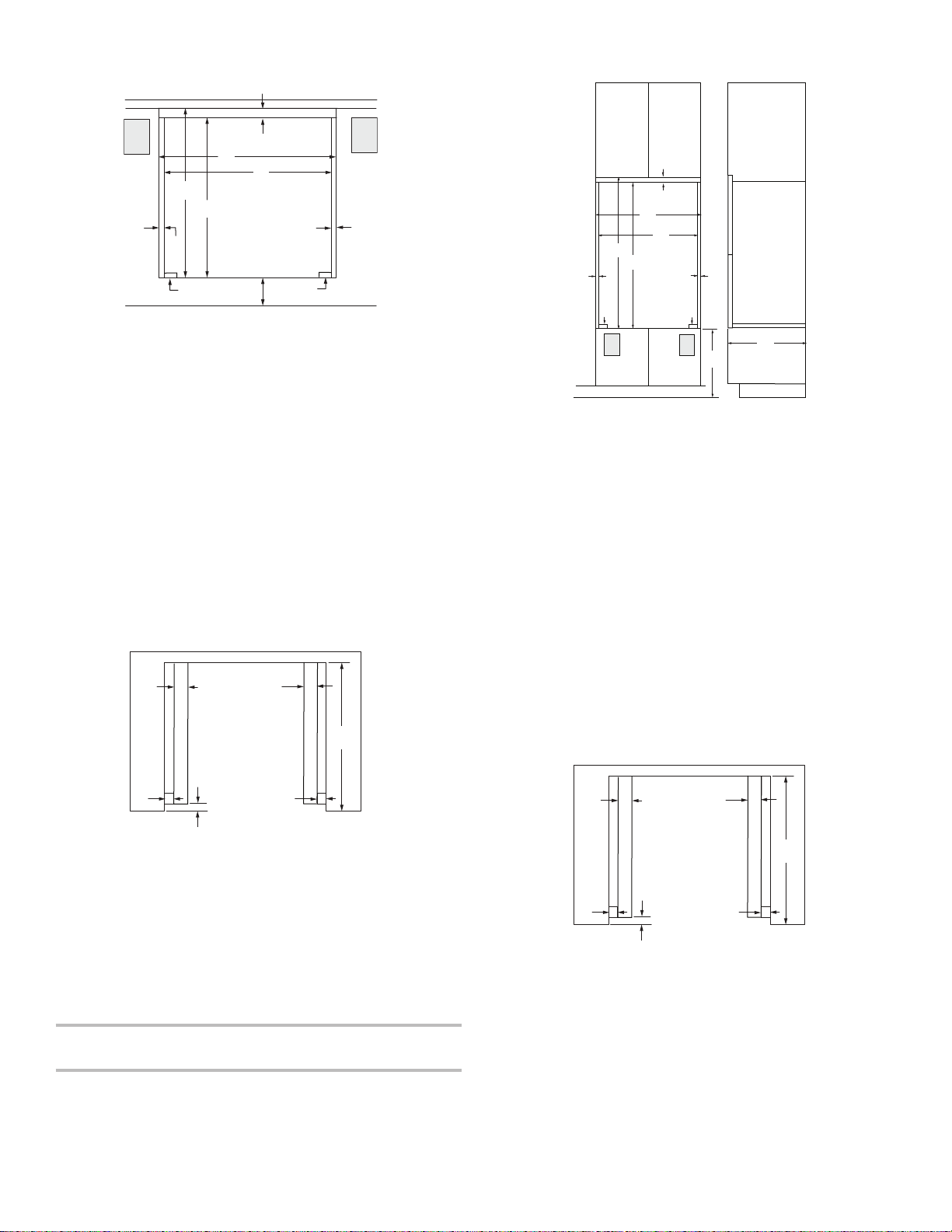
Single Ovens Undercounter - Flush Installations
AA
AA
(without cooktop installed above)
Double Ovens Installed in Cabinet - Flush Installations
A
B
C
D
E
F
G
H
Front View
27" (68.6 cm) Models
A. Recommended junction box
location
B. 3/4" (1.9 cm) top cleat*
C. 271/4" (69.2 cm) minimum width
of flush inset cutout
D. 257/8" (65.7 cm) minimum width
of opening
E. 307/16" (77.3 cm) minimum
height of flush inset cutout
F. 2911⁄16" (75.4 cm) recommended
cutout height
G. 11⁄16" (1.7 cm) side cleat*
H. 1⁄2" x 2" (1.3 cm x 5.1 cm)
spacer the entire depth of the
cutout*
I. 41/16" (10.3 cm) bottom of cutout
to floor
*Cleats and spacers must be recessed 1
front of the cabinet.
I
30" (76.2 cm) Models
A. Recommended junction box
location
B. 3/4" (1.9 cm) top cleat*
C. 301/4" (76.8 cm) minimum width
of flush inset cutout
D. 287/8" (73.3 cm) minimum width
of opening
E. 307/16" (77.3 cm) minimum
height of flush inset cutout
F. 2911⁄16" (75.4 cm) recommended
cutout height
G. 11⁄16" (1.7 cm) side cleat*
H. 1⁄2" x 2" (1.3 cm x 5.1 cm)
spacer the entire depth of the
cutout*
I. 41/16" (10.3 cm) bottom of cutout
to floor
A
G
H
3
8
/
" (3.5 cm) from the
A
B
C
D
E
F
G G
H
Front View
27" (68.6 cm) Models
A. 9⁄16" (1.4 cm) top cleat*
B. 271/4" (69.2 cm) minimum width
of flush inset cutout
C. 257/8" (65.7 cm) minimum width
of opening
D. 533/16" (135.1 cm) minimum
height of flush inset cutout
E. 525/8" (133.6 cm) recommended
cutout height
F. 11⁄16" (1.7 cm) side cleat*
G. 1⁄2" x 2" (1.3 cm x 5.1 cm)
spacer the entire depth of the
cutout*
H. Recommended junction box
location
I. 45/8" - 143/4" (11.7 - 37.5 cm)
bottom of cutout to floor
J. 25" (63.5 cm) minimum depth
of cutout
F
H
J
I
Side View
30" (76.2 cm) Models
A. 9⁄16" (1.4 cm) top cleat*
B. 301/4" (76.8 cm) minimum width
of flush inset cutout
C. 287/8" (73.3 cm) minimum width
of opening
D. 533/16" (135.1 cm) minimum
height of flush inset cutout
E. 525/8" (133.6 cm) recommended
cutout height
F. 11⁄16" (1.7 cm) side cleat*
G. 1⁄2" x 2" (1.3 cm x 5.1 cm)
spacer the entire depth of the
cutout*
H. Recommended junction box
location
I. 45/8" - 143/4" (11.7 - 37.5 cm)
bottom of cutout to floor
J. 25" (63.5 cm) minimum depth
of cutout
B
C
D
D
Top View
27" (68.6 cm) Models
A. 1⁄2" x 2" (1.3 cm x 5.1 cm)
spacer the entire depth of the
cutout*
B. 25" (63.5 cm) depth of cutout
C. 13/8" (3.5 cm) recess from front
of cabinet
D. 11⁄16" (1.7 cm) side cleat*
*Cleats and spacers must be recessed 1
30" (76.2 cm) Models
A. 1⁄2" x 2" (1.3 cm x 5.1 cm)
spacer the entire depth of the
cutout*
B. 25" (63.5 cm) depth of cutout
C. 13/8" (3.5 cm) recess from front
of cabinet
D. 11⁄16" (1.7 cm) side cleat*
3
8
/
" (3.5 cm) from the
front of the cabinet.
Cabinet Dimensions - Double Ovens, Flush
Installations
A 25" (63.5 cm) minimum cutout depth is required.
These dimensions will result in a 1⁄4" (6.3 mm) reveal on the top,
a 1⁄4" (6.3 mm) reveal on the sides, and a 1⁄8" (3.1 mm) reveal on
the bottom of the wall oven.
The front face of the cleats and platform will be visible and
should be treated as a nished surface.
*Cleats and spacers must be recessed 1
front of the cabinet.
C
D
D
Top View
27" (68.6 cm) Models
A. 1⁄2" x 2" (1.3 cm x 5.1 cm)
spacer the entire depth of the
cutout*
B. 25" (63.5 cm) depth of cutout
C. 13/8" (3.5 cm) recess from front
of cabinet
D. 11⁄16" (1.7 cm) side cleat*
30" (76.2 cm) Models
A. 1⁄2" x 2" (1.3 cm x 5.1 cm)
spacer the entire depth of the
cutout*
B. 25" (63.5 cm) depth of cutout
C. 13/8" (3.5 cm) recess from front
of cabinet
D. 11⁄16" (1.7 cm) side cleat*
*Cleats and spacers must be recessed 1
front of the cabinet.
3
8
/
" (3.5 cm) from the
B
3
8
/
" (3.5 cm) from the
4
06-May-2019 13:38:41 EDT | RELEASED
In some European factories the letter "W" of the part code mentioned herein will be automatically
replaced by the number "4000" (e.g. "W12345678" becomes "400012345678")
INSTALLATION INSTRUCTIONS
Prepare Built-In Oven
NOTES:
■ Use these Installation Instructions in conjunction with the
Installation Instructions provided with your built-in oven.
■ Refer and adhere to the “Electrical Requirements” section
and complete the instructions in the “Make Electrical
Connection” section of the Installation Instructions provided
with your built-in oven.
1. Decide on the nal location for the oven. Avoid drilling or
cutting into house wiring during installation.
WARNING
Excessive Weight Hazard
Use two or more people to move and install oven.
Failure to do so can result in back or other injury.
2. To avoid oor damage, set the oven onto cardboard prior to
installation. Do not use the handle or any portion of the front
frame for lifting.
3. Remove the shipping materials and tape from the oven.
Remember to keep the corner posts and other materials that
may be needed for installation.
4. Remove the hardware package from inside the bag
containing literature.
5. Move oven and cardboard close to the oven’s nal location.
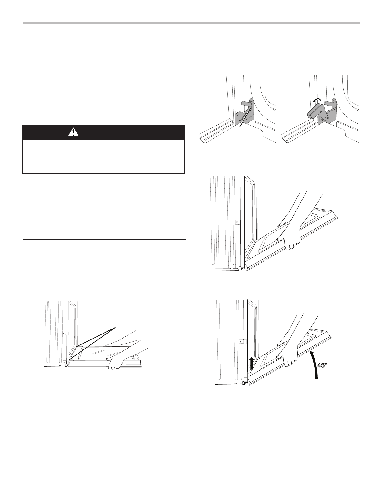
3. Locate the oven door hinge locks in both corners of the oven
door, and rotate the hinge locks toward the oven door to the
unlocked position. If the door hinge lock is not rotated fully
(see illustration B), the door will not remove properly.
Locked
position
Grip here
to rotate
A. Oven door hinge lock in
locked position
4. Gently start to close the door. The door will stop at a partially
closed position.
Unlocked
position
B. Oven door hinge lock in
partially unlocked position
Remove Oven Door(s)
IMPORTANT: Use two hands to remove the oven door(s).
1. Prior to removing the oven door, prepare a surface where
you will place it. This surface should be at and covered with
a soft blanket, or use the corner posts from your packaging
material.
2. Fully open the oven door.
Door
Hinges
5. Using two hands, grasp the edges of the oven door.
Close the oven door slightly past the stop position to take
the weight off of the door hinges, and then pull the oven door
up.
06-May-2019 13:38:41 EDT | RELEASED
In some European factories the letter "W" of the part code mentioned herein will be automatically
replaced by the number "4000" (e.g. "W12345678" becomes "400012345678")
5
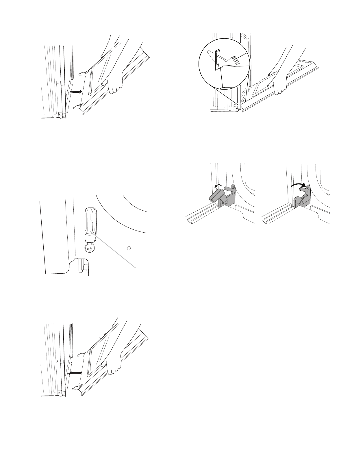
6. Pull the oven door toward you and then remove. You may
Unlocked
p
Locked
need to gently shift door from side to side as you pull.
4. Make sure the door hinge notch is engaged on the bottom of
the oven cavity slot.
7. Set the oven door aside on the prepared covered work
surface with the oven door resting on its handle.
8. To continue with the oven installation, go to the “Positioning
Oven Feet” section.
Replace Oven Door(s)
1. Using two hands, grasp the side edges of the door at the
midpoint. Face the oven cavity.
2. Locate the slots on each side of the oven front frame for the
door hinge locks.
A
A. Slot in the oven cavity for door hinge lock
3. Using two hands, grasp the edges of the oven door. At a 45°
angle, insert the hinges at the same time and push the oven
door into the oven cavity slot to replace. You may need to
gently shift the door from side to side as you push.
IMPORTANT: Do not close the door at this step or damage may
occur to the door hinge.
5. Lower the oven door to the fully open position. If the oven
door does not open to a full 90°, repeat steps 1 through 3.
6. Locate the oven door hinge locks in the corners of the oven
door, and rotate the hinge locks toward the oven cavity to
the locked position.
osition
position
7. After the door hinges have been locked, gently swing the
door upward to close. The door should not be forced closed.
8. When the hinges are properly installed and the door is
closed, there should be an even gap between the door and
the control panel. If one side of the oven door is lower than
the other, the hinge on that side is not properly installed.
See “Remove Oven Door” and “Replace Oven Door.”
6
06-May-2019 13:38:41 EDT | RELEASED
In some European factories the letter "W" of the part code mentioned herein will be automatically
replaced by the number "4000" (e.g. "W12345678" becomes "400012345678")
 Loading...