

JennAir JJD3027IL INSTALLATION INSTRUCTIONS AND OPERATION MANUAL

INSTALLATION INSTRUCTIONS
27" (68.6 CM), AND 30" (76.2 CM) INDOOR/OUTDOOR
ELECTRIC WARMING DRAWER
INSTRUCTIONS D’INSTALLATION
TIROIR-RÉCHAUD ÉLECTRIQUE POUR USAGE INTÉRIEUR/
EXTÉRIEUR DE 27" (68,6 CM), ET 30" (76,2 CM)
Table of Contents/Table des matières
WARMING DRAWER SAFETY.......................................................2
INSTALLATION REQUIREMENTS .................................................3
Tools and Parts .............................................................................3
Location Requirements ................................................................3
Electrical Requirements ...............................................................6
INSTALLATION INSTRUCTIONS ...................................................6
Install Warming Drawer ................................................................6
Complete Installation ...................................................................7
CUSTOM DRAWER FRONT INSTALLATION INSTRUCTIONS
FOR WARMING DRAWERS ...........................................................7
Tools and Parts .............................................................................7
Install Custom Drawer Front Panel ..............................................7
SÉCURITÉ DU TIROIR-RÉCHAUD ...............................................9
EXIGENCES D’INSTALLATION ...................................................10
Outillage et pièces ......................................................................10
Exigences d’emplacement .........................................................10
Electrical Requirements .............................................................13
INSTRUCTIONS D’INSTALLATION .............................................13
Installation du tiroir-réchaud ......................................................13
Achever l’installation ..................................................................14
INSTRUCTIONS D’INSTALLATION DE LA FAÇADE DU TIROIR
PERSONNALISÉ POUR TIROIR-RÉCHAUD ..............................14
Outillage et pièces ......................................................................14
Installation du panneau de la façade du tiroir personnalisé ......14
IMPORTANT:
Save for local electrical inspector’s use.
IMPORTANT:
À conserver pour consultation par l’inspecteur local des installations électriques.
W11295554A
WARMING DRAWER SAFETY
2
INSTALLATION REQUIREMENTS
Tools and Parts
Gather the required tools and parts before starting installation.
Read and follow the instructions provided with any tools listed
here.
Tools Needed
■ Phillips screwdriver
■ Flat-blade screwdriver
■ Measuring tape
■ Level
■ Drill
8
■ 1/
" (3.5 cm) hole saw
Parts Supplied
■ Two #8-18 x 1/2" (1.3 cm) screws
■ Lens (for panel ready models)
Check local codes. Check existing electrical supply. See
“Electrical Requirements.”
It is recommended that all electrical connections be made by a
licensed, qualied electrical installer.
Location Requirements
IMPORTANT: Observe all governing codes and ordinances.
■ Cutout dimensions that are shown must be used. Given
dimensions provide minimum clearance with warming
drawer.
■ Recessed installation area must provide complete enclosure
around the recessed portion of the warming drawer.
■ Grounded electrical supply is required. See “Electrical
Requirements” section.
■ Electrical supply outlet should be located in the rear wall
on the upper right-hand side of the cutout or in an adjacent
cabinet. The outlet must be recessed. If the electrical outlet
is located in an adjacent cabinet, a 13/8" (3.5 cm) minimum
diameter hole should have been drilled in the back of the
cutout or support surface to pass the power supply cord
through to the outlet.
■ Warming drawer support surface must be solid, level,and
ush with bottom of cabinet cutout.
■ Warming drawers with oiled bronze, black glass, and white
glass panels are approved for indoor use only.
■ Support surface must be solid, level, and ush with the
bottom of the cabinet cutout.
■ 24" (61.0 cm) minimum cabinet depth.
For best performance results make sure the warming drawer is
leveled before completing installation. There is no way to level
the warming drawer after it has been installed. If the installation
is not level, the door may slide open or not seal tightly, allowing
heat to escape.
NOTE: If installing the warming drawer below another product,
refer to that product’s literature for any installation requirements.
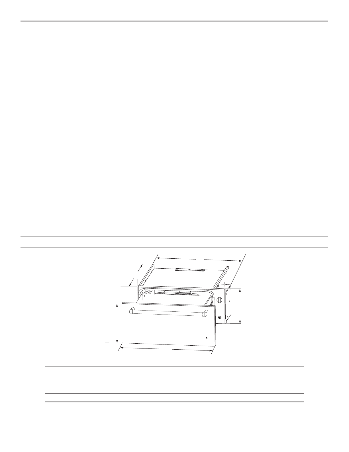
Product Dimensions
WARMING
DRAWER SIZE
27" (68.6 cm) 23/8" (58.7 cm) 25¼" (64.1 cm) 9" (22.9 cm) 26¾" (67.9 cm) 10¼" (26.1 cm)
30" (76.2 cm) 23/8" (58.7 cm) 28¼" (71.8 cm) 9" (22.9 cm) 29¾" (75.6 cm) 10¼" (26.1 cm)
E
OVEN DEPTH
(A)
A
RECESSED
WIDTH (B)
D
RECESSED
HEIGHT (C)
B
C
OVERALL
WIDTH (D)
DRAWER
FRONT HEIGHT
(E)
3
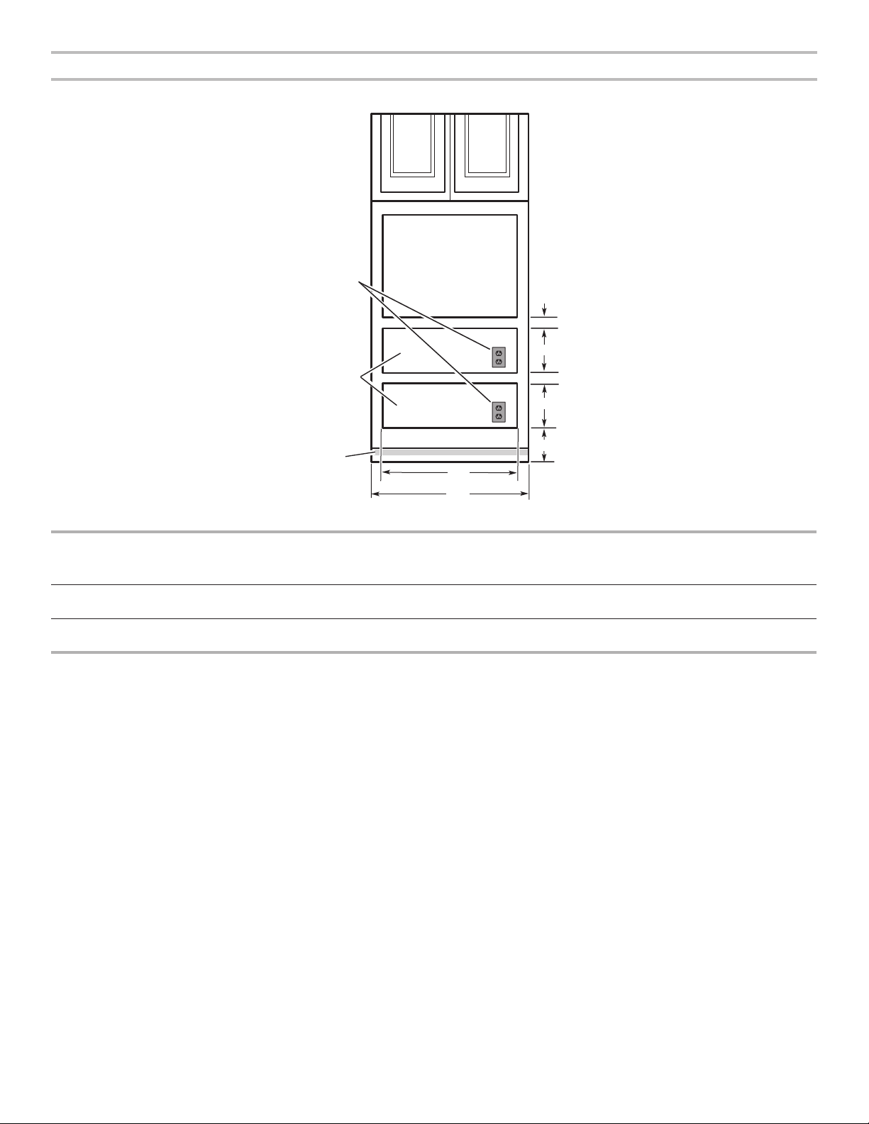
Clearance Dimensions
E
Front view
120 V
grounded
outlet
(or located
in adjacent
cabinet)
A
Warming
drawer
cutouts
Toe
kick
D
WARMING
DRAWER SIZE
MINIMUM
BETWEEN
CUTOUT
HEIGHT (B)
MINIMUM/
RECOMMENDED (C)
CUTOUTS (A)
27" (68.6 cm) 2½" (6.4 cm) 9/8" (23.2 cm) 1" (2.5 cm)/
30" (76.2 cm) 2½" (6.4 cm) 9/8" (23.2 cm) 1" (2.5 cm)/
Warming drawer can be installed as an indoor single or double
installation or installed under a single oven. Two warming
drawers under a single oven are shown.
NOTE: The warming drawer cannot be leveled after being
installed.
For outdoor installation, follow the cutout dimensions above.
Install the outdoor warming drawer in a permanent xture.
4¼" (10.8 cm)
4¼" (10.8 cm)
Custom Wood Drawer Front
If you plan to install a custom wood panel to match your
cabinets, we recommend consulting a qualied cabinetmaker or
carpenter. The back of the wood panel must be sealed to avoid
moisture damage.
B
A
B
C
CUTOUT
WIDTH (D)
MINIMUM
CABINET
WIDTH (E)
25½" (64.8 cm) 27" (68.6 cm)
28½" (72.4 cm) 30" (76.2 cm)
4
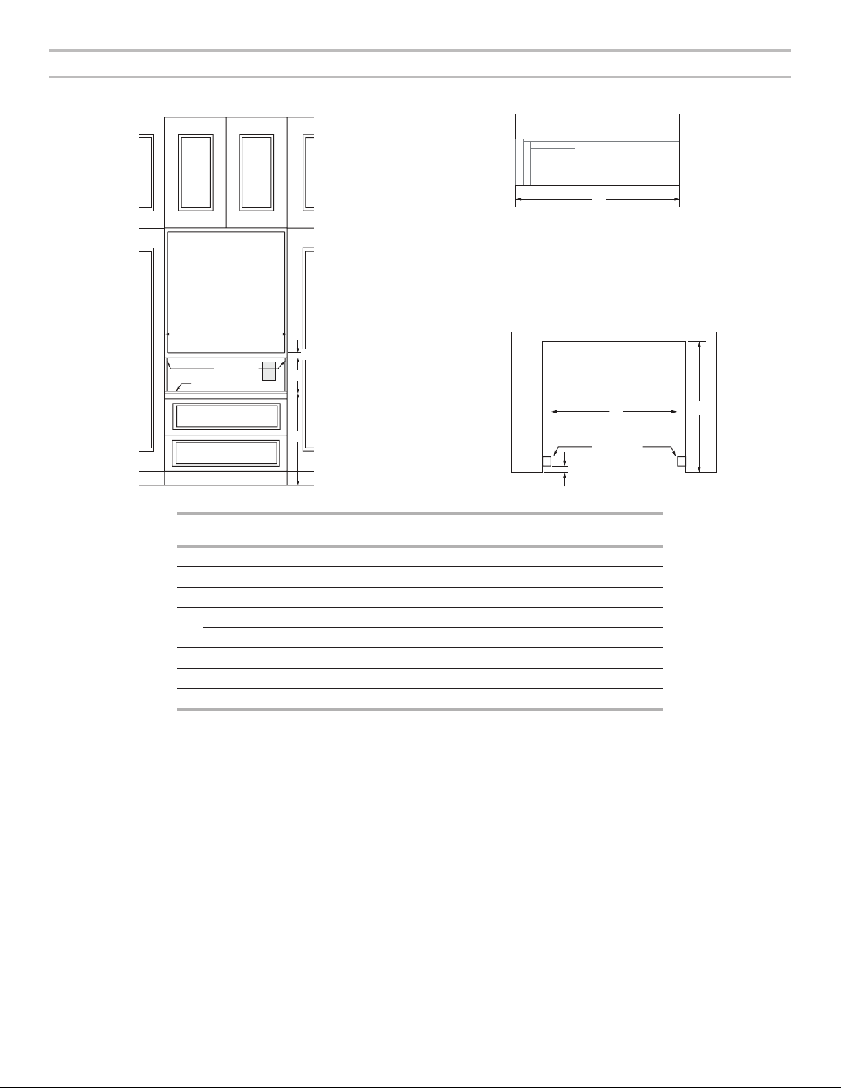
Clearance Dimensions - Flush Installation
Front View
Cabinet
Side View
Back
F
A
B
e
C
D
1⁵⁄₈" (4.1 cm)
27" (68.6 cm)
Models
30" (76.2 cm)
Models
1" (25 mm)
Side Cleats*
7/8" (22 mm)
Platform*
Width of ush inset cutout (minimum) 27¼" (69.2 cm) 30¼" (76.8 cm)
A
Height between cutouts (minimum) 2½" (6.4 cm) 2½" (6.4 cm)
B
Height of ush inset cutout (minimum) 10¾" (27.3 cm) 10¾" (27.3 cm)
C
Bottom of cutout to oor (recommended) 8¼" (21.0 cm) 8¼" (21.0 cm)
D
Bottom of cutout to oor (minimum) 5" (12.7 cm) 5" (12.7 cm)
Width of opening (minimum) 25¼" (64.1 cm) 28¼" (71.8 cm)
E
Depth of cutout (minimum) 25" (63.5 cm) 25" (63.5 cm)
F
Recommended outlet location
e
Flush Installation Requirements
Top View
A 25" (63.5 cm) minimum cutout depth is required.
These dimensions will result in a 1/4" (6 mm) reveal on all sides of the warming drawer.
* The front face of the cleats and platforms will be visible and should be treated as a nished surface.
E
Side Cleat*
F
5
 Loading...