

Jenn-Air JGW8130DD series Service Manual

Service
This manual is to be used by qualified appliance
technicians only. Maytag does not assume any
responsibility for property damage or personal
injury for improper service procedures done by
an unqualified person.
This Base Manual covers general information
Refer to individual Technical Sheet
for information on specific models
This manual includes, but is
not limited to the following:
Gas
Wall Oven
JGW8130DD*
16022514
Revision 0
May 2004
Important Information
Important Notices for Servicers and Consumers
Maytag will not be responsible for personal injury or property damage from improper service procedures. Pride and
workmanship go into every product to provide our customers with quality products. It is possible, however, that during
its lifetime a product may require service. Products should be serviced only by a qualified service technician who is
familiar with the safety procedures required in the repair and who is equipped with the proper tools, parts, testing
instruments and the appropriate service information. IT IS THE TECHNICIANS RESPONSIBILITY TO REVIEW ALL
APPROPRIATE SERVICE INFORMATION BEFORE BEGINNING REPAIRS.
!
To avoid risk of severe personal injury or death, disconnect power before working/servicing on appliance to avoid
electrical shock.
To locate an authorized servicer, please consult your telephone book or the dealer from whom you purchased this
product. For further assistance, please contact:
WARNING
Customer Service Support Center
CAIR Center
Web Site Telephone Number
WWW.JENNAIR.COM ............................................. 1-800-536-6247
WWW.MAYTAG.COM ............................................. 1-800-688-9900
CAIR Center in Canada ........................................... 1-800-688-2002
Recognize Safety Symbols, Words, and Labels
DANGER!
DANGER—Immediate hazards which WILL result in severe personal injury or death.
WARNING!
WARNING—Hazards or unsafe practices which COULD result in severe personal injury or death.
CAUTION!
CAUTION—Hazards or unsafe practices which COULD result in minor personal injury, product or property
damage.
2 16022514 Rev. 0 © 2004 Maytag Services

Table of Contents
Important Information .................................................... 2
Safety Information
Safety Practices for Servicer .................................... 5
Servicing .................................................................. 5
Receiving Wall Oven ................................................ 5
ALL APPLIANCES ................................................... 5
SELF-CLEANING OVEN .......................................... 5
OVEN ...................................................................... 6
Delayed Ignition ....................................................... 6
Precautions .............................................................. 6
In Case of Fire.......................................................... 6
Using the Oven ........................................................ 6
Self-Cleaning Oven ................................................... 7
Baking, Broiling, and Roasting ................................. 7
Connecting Wall Oven to Gas .................................. 7
Electrical Requirements ........................................... 8
Extension Cord ........................................................ 8
Grounding ................................................................ 8
Product Safety Devices ............................................ 9
General Information
Cooking Nomenclature ............................................ 10
Rating Label ............................................................ 11
Functional Operation ............................................... 11
Specifications .........................................................12
Model Identification ................................................. 12
Service .................................................................... 12
Parts and Accessories ............................................ 12
Extended Service Plan ............................................ 12
Troubleshooting Procedures .................................. 13 -14
Testing Procedures ...................................................... 15
Quick Test Mode for Electronic Range Control........ 19
Disassembly Procedures
Removing and Replacing Oven ................................ 21
Control Panel Assembly..........................................21
Control Board .......................................................... 21
Control Panel .......................................................... 21
Temperature Hi-Limit Switch ................................... 21
Oven Sensor ........................................................... 21
Oven Door Latch ..................................................... 22
Door Plunger Light Switch Assembly ......................22
Oven Light Bulb/Oven Light Socket .........................22
Oven Door Removal ................................................. 22
Frameless Door Disassembly ................................. 22
Oven Door Hinge ..................................................... 23
Blower Motor ........................................................... 23
Vent Assembly .......................................................23
Broil Ignitor .............................................................. 23
Broil Burner ............................................................. 23
Oven Burner Ignitor .................................................. 24
Oven Burner ............................................................ 24
Pressure Regulator / Shut-Off Valve ........................ 24
Gas Valve ............................................................... 24
Door Assembly ....................................................... 25
Appendix A
Installation Manual ................................................ A-2
Mobile Homes .................................................... A-3
Recreational Vehicles ........................................ A-3
Clearance Dimensions ....................................... A-3
Locating The Unit ............................................... A-3
Connecting The Oven ......................................... A-5
Unit Adjustments
Gas Conversion ................................................. A-7
Bake and Broil Burners to LP/Propane
Gas Conversion .............................................. A-9
Appendix B
Use and Care Information ...................................... B-2
Important Safety Instructions ............................. B-2
Oven Cooking .................................................... B-5
Care & Cleaning ............................................... B-13
Maintenance .................................................... B-16
Troubleshooting ............................................... B-18
Warranty .......................................................... B-20
Appendix C
Conversion Instructions ......................................... C-2
Gas Conversion ................................................. C-2
Bake and Broil Burners to LP/Propane
Gas Conversion .............................................. C-3
Unit Adjustments ............................................... C-4
............................................... A-6
© 2004 Maytag Services 16022514 Rev. 0 3
Safety Information
As with all appliances, there are certain rules to follow for
safe operation. Verify everyone who operates the oven is
familiar with the operations and with these precautions.
Use appliance only for its intended purpose as described.
Pay close attention to the safety sections of this manual.
Recognize the safety section by looking for the symbol
or the word safety.
Recognize this symbol as a safety precaution.
!
!
WARNI NG
This gas appliance contains or produces a chemical or
chemicals which are known to the state of California to
cause cancer, birth defects or other reproductive harm.
To reduce the risk from substances in the fuel or from
fuel combustion make sure this appliance is installed,
operated, and maintained according to the instructions
in this manual.
Due to the nature of cooking, fires can occur as a
result of overcooking or excessive grease. Although a
fire is unlikely, if one occurs proceed as follows:
!
WARNI NG
If the information in this manual is not followed exactly,
a fire or explosion may result causing property
damage, personal injury or death.
Do not store or use gasoline or other flammable vapors
or liquids in the vicinity of this or any other appliance.
WHAT TO DO IF YOU SMELL GAS
• Extinguish any open flame.
• Do not try to light any appliance.
• Do not touch any electrical switch; do not use any
phone in your building.
• Immediately call your gas supplier from a neighbor’s
phone. Follow the gas supplier’s instructions.
• If you cannot reach your gas supplier, call the fire
department.
Installation and service must be performed by an
authorized installer, service agency or gas supplier.
Oven Fires
1. Do not open the oven door.
2. Turn all controls to the OFF position.
3. As an added precaution turn off the electricity at
the main circuit breaker or fuse box and the gas
at the main supply valve.
4. Allow the food or grease to burn itself out in the
oven.
If smoke or fire persist call the local fire department.
To avoid risk of property damage or personal injury do
not obstruct the flow of combustion or ventilation air to
the oven.
To avoid risk of electrical shock, serious personal injury
or death: Verfiy the oven has been properly grounded
and always disconnect the electrical supply before
servicing this unit.
NOTE: The maximum gas supply pressure for these
models must not exceed 14 inches W.C.P.
!
WARNI NG
To avoid risk of electrical shock, property damage,
personal injury or death; verify wiring is correct, if
components were replaced. Verify proper and complete
operation of unit after servicing.
4 16022514 Rev. 0 © 2004 Maytag Services

Safety Information
Safety Practices for Servicer
Safe and satisfactory operation of gas wall ovens
depends upon its design and proper installation. However,
there is one more area of safety to be considered:
Servicing
Listed below are some general precautions and safety
practices which should be followed in order to protect the
service technician and consumer during service and after
service has been completed.
1. Gas smell—Extinguish any and all open flames and
open windows.
2. Turn gas off—Service wall oven with gas turned off
unless testing requires it.
3. Checking for gas leaks—Never check for leaks with
any kind of open flame. Soap and water solution
should be used for this purpose. Apply solution to
suspected area and watch for air bubbles which
indicates a leak. Correct leaks by tightening fittings,
screws, connections, applying approved compound,
or installing new parts.
4. Using lights—Use a hand flashlight when servicing
wall ovens or checking for gas leaks. Electric
switches should not be operated where leaks are
suspected. This will avoid creating arcing or sparks
which could ignite the gas. If electric lights are
already turned on, they should not be turned off.
5. Do not smoke—Never smoke while servicing gas wall
ovens, especially when working on piping that
contains or has contained gas.
6. Check wall oven when service is completed—
After servicing, make visual checks on electrical
connection, and check for gas leaks. Inform
consumer of the condition of wall oven before leaving.
7. Adhere to all local regulations and codes when
performing service.
• Ensure wall oven is correctly adjusted by a qualified
service technician or installer for the type of gas
(Natural or LP). Some wall ovens can be converted for
use with Natural or LP gas.
• With prolonged use of a wall oven, high floor
temperatures could result. Many floor coverings will not
be able to withstand this kind of use. Never install wall
oven over vinyl tile or linoleum that cannot withstand
high temperatures. Never install wall oven directly over
carpeting.
ALL APPLIANCES
1. Proper Installation—Be sure your appliance is
properly installed and grounded by a qualified
technician.
2. Never Use Appliance for Warming or Heating the
Room.
3. Do Not Leave Children Alone—Children should not be
alone or unattended in the area where the appliance
is in use. They should never be allowed to sit or stand
on any part of the appliance.
4. Wear Proper Apparel—Loose fitting or hanging
garments should never be worn while using appliance.
5. User Servicing—Do not repair or replace any part of
the appliance unless specifically recommended in the
manual. All other servicing should be referred to a
qualified technician.
6. Storage in or on Appliance—Flammable materials
should not be stored in oven.
7. Do Not Use Water on Grease Fires—Smother fire or
flame, or use dry chemical or foam-type extinguisher.
8. Use Only Dry Potholders—Moist or damp potholders
on hot surfaces may result in burns from steam. Do
not let potholder touch burners. Do not use a towel or
other bulky cloth.
Receiving Wall Oven
• Installer needs to show consumer location of the wall
oven gas shut-off valve and how to shut it off.
• Authorized servicer must install the wall oven, in
accordance with the Installation Instructions.
Adjustments and service should be performed only by
authorized servicer.
• Plug wall oven into a 120–volt grounded outlet only. Do
not remove round grounding prong from the plug. If in
doubt about grounding of the home electrical system, it
is consumers responsibility and obligation to have an
ungrounded outlet replaced with a properly grounded
three-prong outlet in accordance with the National
Electrical Code. Do not use an extension cord with this
appliance.
• Insure all packing materials are removed from the wall
oven before operating it, to prevent fire or smoke
damage should the packing material ignite.
© 2004 Maytag Services 16022514 Rev. 0 5
SELF-CLEANING OVEN
1. Do Not Clean Door Gasket—The door gasket is
essential for a good seal. Care should be taken not to
rub, damage, or move the gasket.
2. Do Not Use Oven Cleaners—No commercial oven
cleaner or oven liner protective coating of any kind
should be used in or around any part of the liner.
3. Clean Only Parts Listed in Manual. See
section.
4. Before Self-Cleaning the Oven—Remove broiler pan,
oven racks, and other utensils.
5. Remove all items from oven top and backguard.
Cleaning

Safety Information
OVEN
1. Use Care When Opening Door—Let hot air or steam
escape before removing or replacing food.
2. Do Not Heat Unopened Food Containers—Build-up of
pressure may cause container to burst and result in
injury.
3. Keep Oven Vents Ducts Unobstructed.
4. Placement of Oven Racks—Always place oven racks
in desired location while oven is cool. If rack is
removed while oven is hot, do not let potholder
contact hot heating element in oven.
Delayed Ignition
Bake Burner Flame
Allow no more than 40–60 seconds before burner ignites
and heat is felt. To check for heat, open oven door to first
stop and place hand over oven door. If heat is not felt,
cancel bake funtion. If burner repeatedly fails to ignite,
contact an authorized servicer.
Broiler Flame
Allow no more than 40–60 seconds before burner ignites
and flame is seen. If burner does not ignite cancel broil
function. If burner repeatedly fails to ignite within 40–60
seconds contact an authorized servicer.
Precautions
• Do not mix household cleaning products. Chemical
mixtures may interact with objectionable or even
hazardous results.
• Do not put plastic items on warm cooking areas. They
may stick and melt.
• Do not use damp sponge or dishcloth to clean oven
when oven is hot. Steam from sponge or dishcloth can
burn.
• Do not leave fat heating unless you remain nearby. Fat
can ignite if overheated by spilling onto hot surfaces.
In Case of Fire
Fires can occur as a result of over cooking or excessive
grease. Though a fire is unlikely, if one occurs, proceed
as follows:
Oven Fires
1. If you see smoke from oven, do not open oven door.
2. Turn oven control to
3. As an added precaution, turn off gas supply and
power at main circuit breaker or fuse box.
4. Turn on vent to remove smoke.
5. Allow food or grease to burn itself out in oven.
6. If smoke and fire persist, call fire department.
7. If there is any damage to components, call repair
service before using oven.
If smoke or fire persist call the local fire department.
To avoid the risk of property damage or personal injury do
not obstruct the flow of combustion or ventilation air to
the oven.
To avoid the risk of electrical shock, serious personal
injury or death: Make sure your oven has been properly
grounded and always disconnect the electrical supply
before servicing this unit.
NOTE: The maximum gas supply pressure for these
models must not exceed 14 inches W.C.P.
OFF
.
Using the Oven
• Do not leave children alone or unattended where a wall
oven is hot or in operation. They could be seriously
burned.
• Do not allow anyone to climb, stand or hang on the
door. They could damage the wall oven and cause
severe personal injury.
• Wear proper apparel. Loose fitting or hanging garments
should never be worn when using oven. Flammable
material could ignite if brought in contact with flame or
hot oven surfaces which may cause severe burns.
• Never use wall oven for warming or heating a room.
This may cause burns, injuries, or a fire.
• Do not use water on grease fires.
• Do not let grease or other flammable materials collect
in or around wall oven.
• Do not repair or replace any part of wall oven unless it
is recommended in this manual.
• Use only dry potholders. Moist or damp potholders
used on hot surfaces may result in a burn from steam.
Do not let a potholder touch the flame. Do not use a
towel or a bulky cloth as a potholder.
• Never leave wall oven unattended while cooking.
Boilovers can cause smoking and may ignite.
6 16022514 Rev. 0 © 2004 Maytag Services
Safety Information
• Only certain types of glass/ceramic, earthenware, or
other glazed utensils are suitable for oven use.
Unsuitable utensils may break due to sudden
temperature change.
• Use care when opening oven door. Let hot air or steam
escape before removing or replacing food.
• Do not heat unopened food containers in oven.
Build-up of pressure may cause a container to burst
and result in injury.
• Keep wall oven vent ducts unobstructed.
• Place oven racks in desired location while oven is cool.
If a rack must be moved while oven is hot, use a dry
potholder.
• Do not use aluminum foil to line oven bottom or racks.
Aluminum foil can cause a fire and will seriously affect
baking results, and damage to porcelain surface's.
• Do not touch interior surfaces of oven during or
immediately after use. Do not let clothing or other
flammable materials come in contact with bake or broil
burners.
• Other areas of the oven can become hot enough to
cause burns, such as vent openings, window, oven door
and oven racks.
• To avoid steam burns, do not use a wet sponge or cloth
to wipe up spills on hot cooking area.
• Do not store combustible or flammable materials, such
as gasoline or other flammable vapors and liquids near
or in oven.
• Do not clean oven door gasket located on back of the
door. Gasket is necessary to seal the oven and can be
damaged as a result of rubbing or being moved.
• Do not drape towels or any materials on oven door
handles. These items may ignite causing a fire.
Self-Cleaning Oven
• Do not clean door gasket. Door gasket is essential for
a good seal. Be careful not to rub, damage or move it.
• Do not use oven cleaners. No commercial oven cleaner
or oven liner protective coating of any kind should be
used in or around any part of the oven.
• Remove the broiler pan and other cookware before selfcleaning oven.
Baking, Broiling, and Roasting
• Do not use oven area for storage.
• Stand back from wall oven when opening door of a hot
oven. Hot air or steam can cause burns to hands, face,
and eyes.
• Do not use aluminum foil anywhere in the oven. This
could result in a fire hazard and damage the wall oven.
• Use only glass cookware appropriate for use in gas
ovens.
• Always remove broiler pan from oven when finished
broiling. Grease left in pan can catch fire if oven is used
without removing grease from the broiler pan.
• When broiling, meat that is close to the flame, may
ignite. Trim any excess fat to help prevent excessive
flare-ups.
• Make sure broiler pan is placed correctly to reduce any
possibility of grease fires.
• Should a grease fire occur in the broiler pan, turn off
oven, and keep oven door closed until fire burns out.
Connecting Wall Oven to Gas
Install manual shut-off valve in gas line for easy
accessibility outside wall oven. Be aware of the location
of the shut-off valve.
CAUTI ON
!
Do not store items of interest to children in cabinets
above wall oven. Children may climb on oven to reach
these items and become seriously injured.
© 2004 Maytag Services 16022514 Rev. 0 7
Safety Information
Electrical Requirements
120-volt, 60 Hertz, 15 amp, individual circuit which is
properly grounded, polarized and protected by a circuit
breaker or fuse.
Extension Cord
Due to possible pinching during installation, extension
cords should not be used on products.
Extension cords will adversely affect the performance of
spark system.
Grounding
NOTE: This appliance must be properly grounded, for
personal safety.
Power cord on this appliance is equipped with a threeprong grounding plug. This matches standard three-prong
grounding wall receptacle to prevent possibility of electric
shock from this appliance.
Consumer should have wall receptacle and circuit
checked by qualified electrician to verify receptacle is
properly grounded.
WARNI NG
!
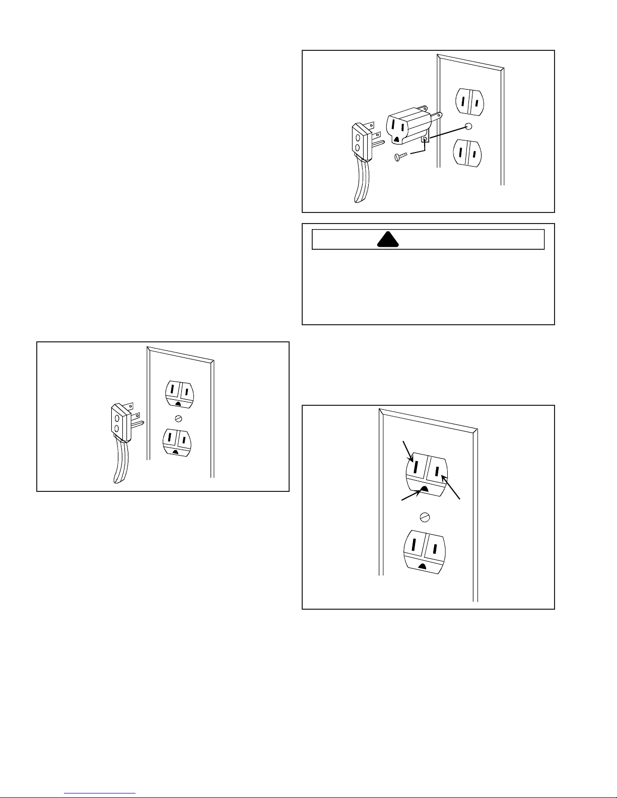
Attaching adapter ground terminal to wall receptacle
cover screw does not ground appliance unless the
cover screw is metal and not insulated, and wall
receptacle is grounded through the house wiring.
Consumer should have circuit checked by a qualified
electrician to verify receptacle is properly grounded.
When disconnecting power cord from adapter, always
hold adapter with one hand. If this is not done, adapter
ground terminal is very likely to break with repeated use.
Should this happen, DO NOT USE appliance until a
proper ground has been established.
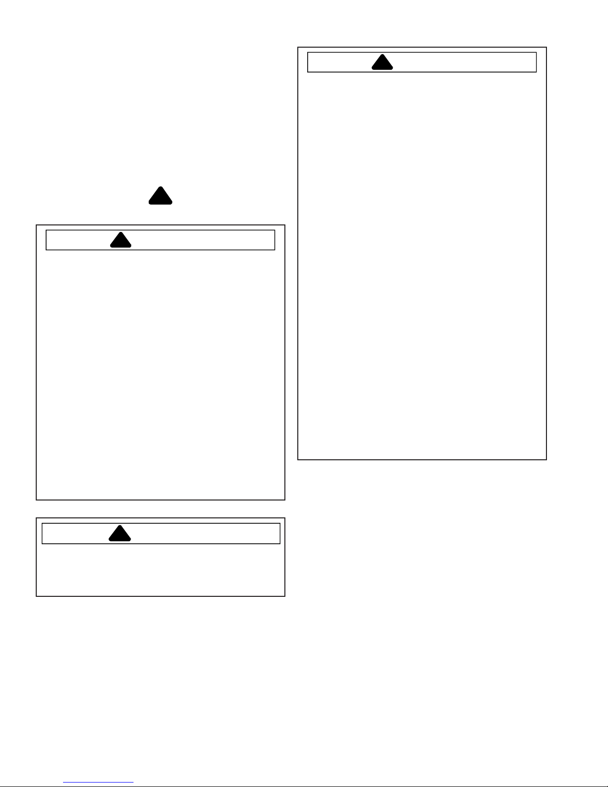
Where standard two-prong wall receptacle is
encountered, it is consumers responsibility and
obligation to have it replaced with a properly grounded
three-prong wall receptacle.
DO NOT, UNDER ANY CIRCUMSTANCES, CUT OR
REMOVE THE THIRD (GROUND) PRONG FROM
POWER CORD.
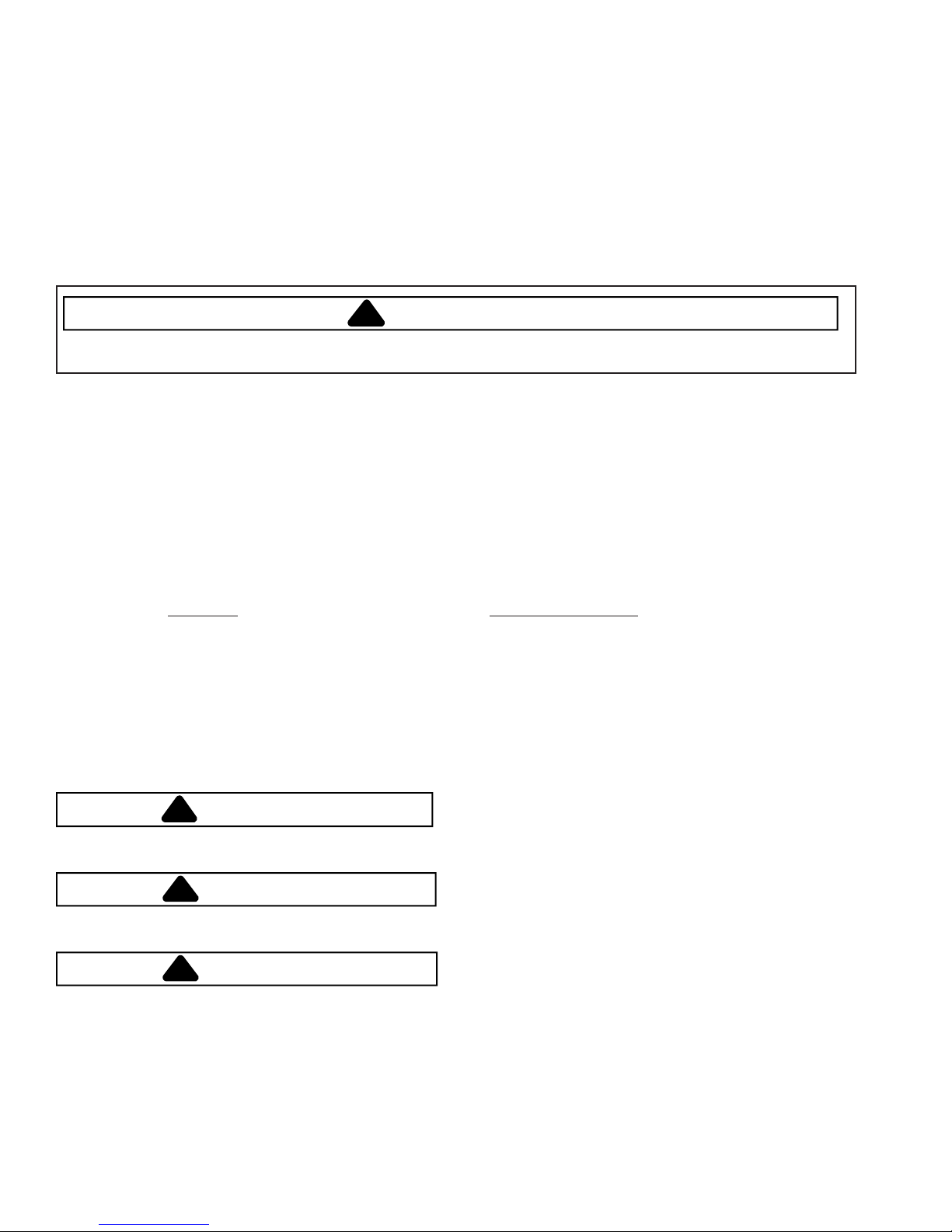
For 15 amp circuits only. Do not use an adapter on 20
amp. circuit. Where local codes permit, a TEMPORARY
CONNECTION may be made to properly grounded twoprong wall receptacle by the use of a UL listed adapter
available at most hardware stores.
Larger slot on adapter must be aligned with larger slot in
the wall receptacle to provide proper polarity.
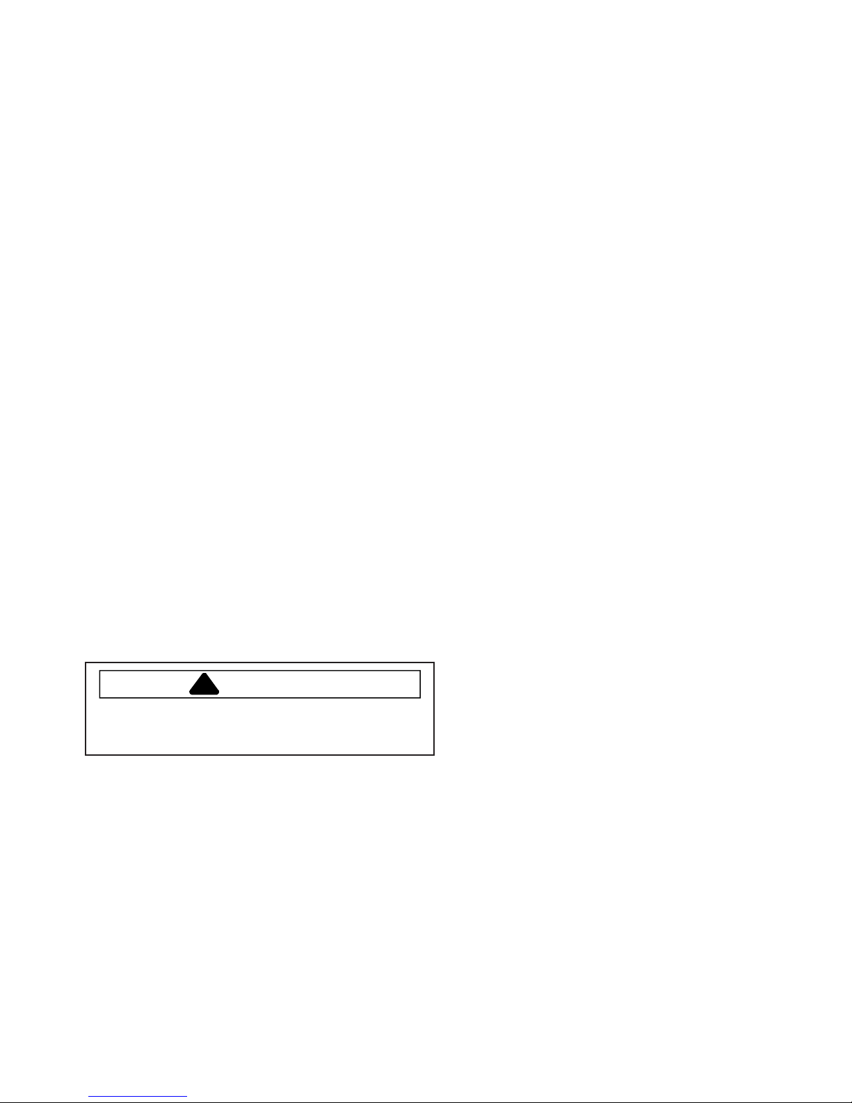
Neutral Wire
Ground
NOTE: Circuit tester can be use to verify voltage is
present at the outlet, connect one lead to hot
line and the other lead to ground, circuit tester
should light.
Hot Line
8 16022514 Rev. 0 © 2004 Maytag Services

Safety Information
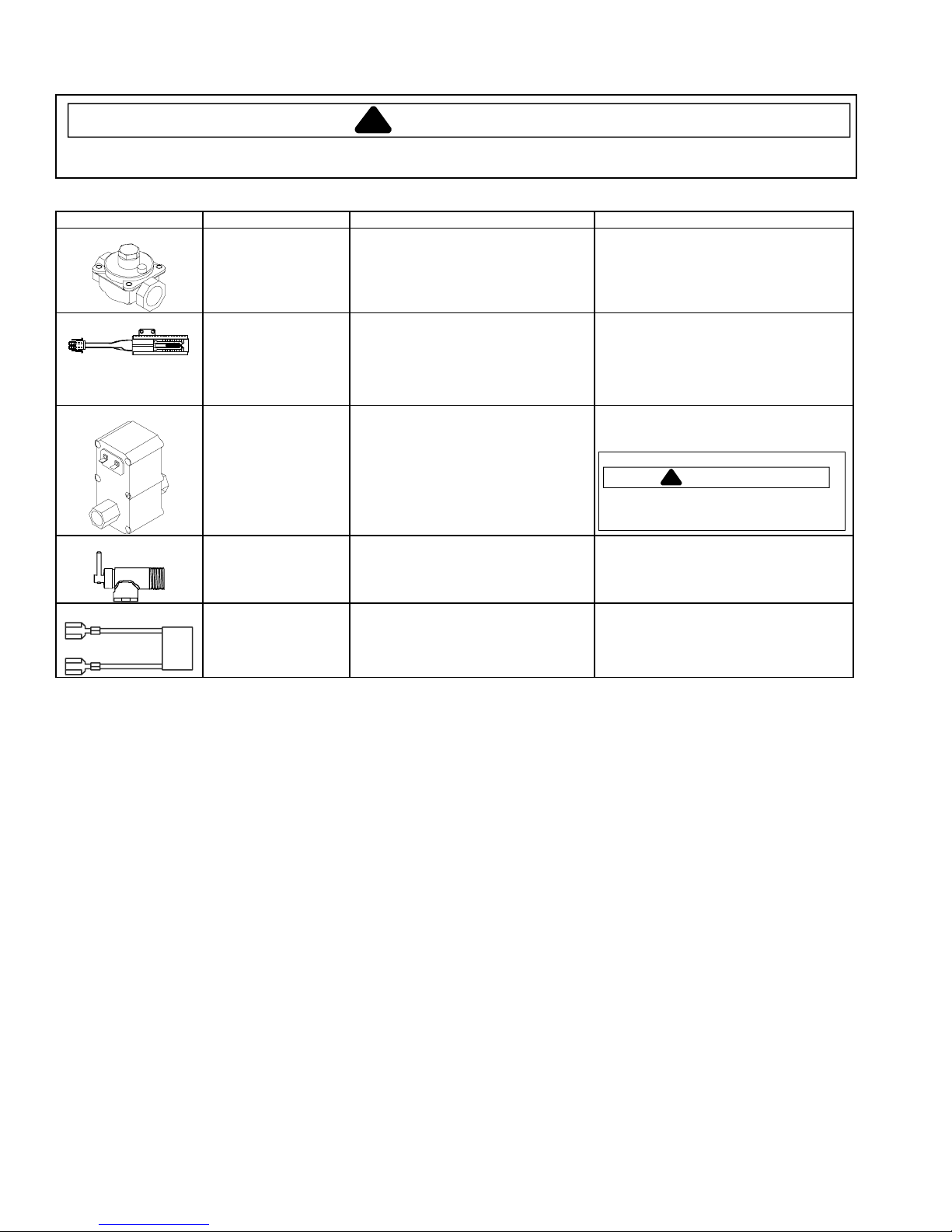
Product Safety Devices
Safety devices and features have been engineered into the product to protect consumer and servicer. Safety devices
must never be removed, bypassed, or altered in such a manner as to defeat the purpose for which they were intended.
Listed below are various safety devices together with the reason each device is incorporated in the gas ranges.
Pressure Regulator Maintains proper and steady gas pressure for operation of oven controls. Regulator
must be set for the type of gas being used Natural or LP. After servicing regulator,
make certain it is set properly before completing service.
Gas Burner Orifices Universal orifices are used on most valves. They must be adjusted or set for the type
of gas being used Natural
After servicing a valve or orifice verify it is adjusted properly before completing service.
Oven Safety Valve Oven valve is designed to be a safety valve. Two basic designs are used in gas
ranges.
Hydraulic type valve
Electric type valve
Both types are safety valves because they are indirectly operated by the oven
thermostat, which controls a pilot flame or electric ignitor, to open and close the oven
valve.
or LP.
Grounded Oven Frame Ground prong on power cord is connected to the frame, usually a green lead fastened
by a screw. In addition, any part or component capable of conducting an electric
current is grounded by its mounting.
If any ground wire, screw, strap, nut, etc. is removed for service, or any reason, it
must be reconnected to its original position with original fastener before the appliance
is put into operation again.
Failure to do so can create a possible shock hazard.
© 2004 Maytag Services 16022514 Rev. 0 9
General Information
This manual provides basic instructions and suggestions
for handling, installing , and servicing gas wallovens.
The directions, information, and warnings in this manual
are developed from experience with, and careful testing of
the product. If the unit is installed according to the
Installation Instructions, it will operate properly and will
require minimal servicing. A unit in proper operating order
ensures the consumer all the benefits provided by
efficient gas cooking.
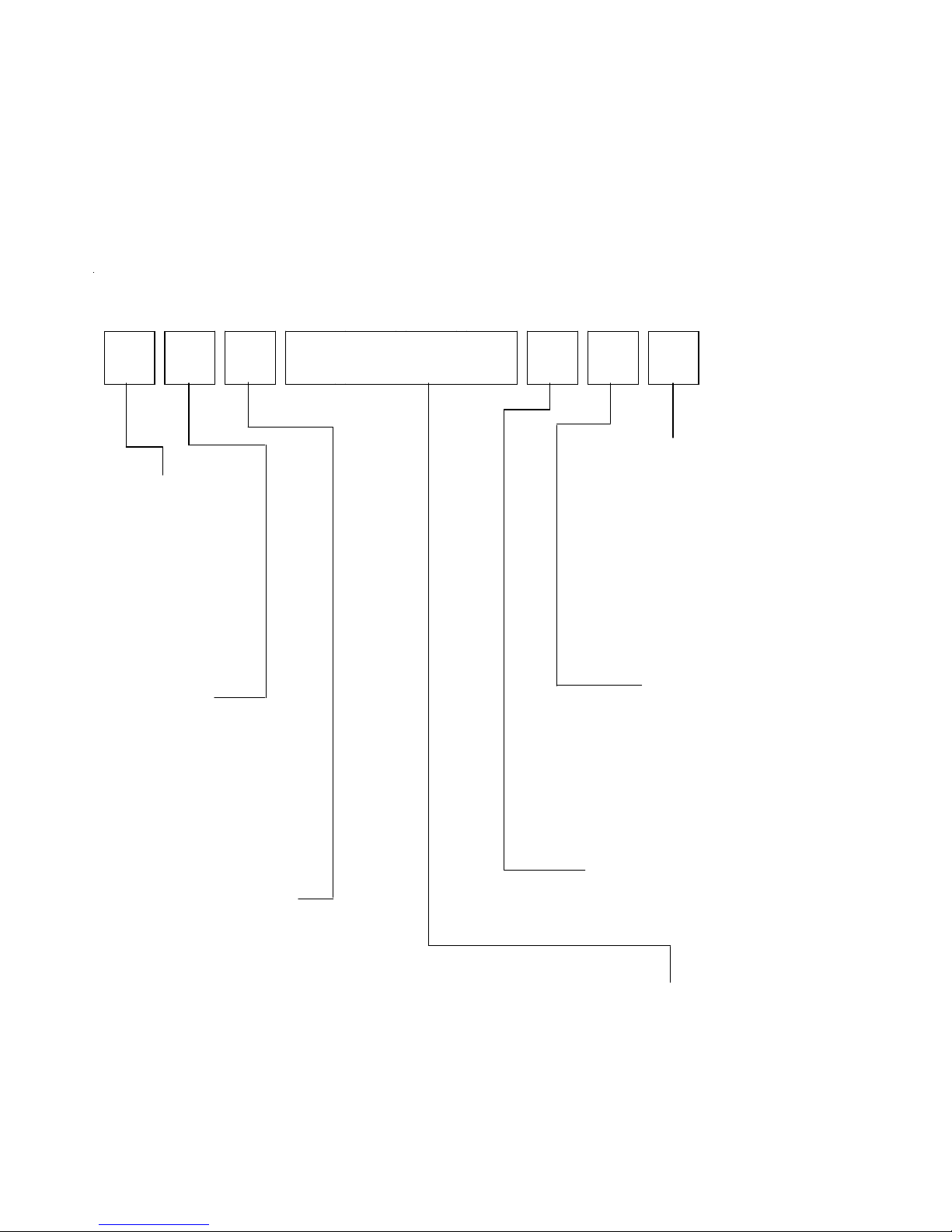
Cooking Nomenclature
J G W 8 1 3 0 D D W
Brand
A Amana
C Magic Chief
G Graffer &
Sattler
H Hardwick
J Jenn-Air
M Maytag
N Norge
U Universal
Y Crosley
This manual contains information needed by authorized
service technicians to install and service gas wallovens
pertaining to this manual. There maybe, however some
information which needs further explanation. Refer to
individual Installation Instructions, Use and Care,
Technical Sheets, or toll free technical support line to
answer questions from authorized service technicians.
Color
A Almond on Almond
B Black
C Brushed Chrome
H Traditional White
L Traditional Almond
P Prostyle
Q Monochromatic Bisque
S Stainless
T Traditional Bisque
W White on White
F Frost White (True Color White)
N Natural Bisque (True Color Bisque)
Fuel
B Butane
D Dual Fuel
E/J Electric
G Gas, Natural
L Liquid Propane
M Microwave
P Standing Pilot
X No Fuel
W Warming Drawer
Product Type
A Accessory/Cartridge
C Cooktop Updraft/Countertop
D Downdraft Cooktop or Warming Drawer
E Eyelevel Range
G Grill
L Range (20")
M Range (36")
P Drop In (24")
Q Wall Oven (27")
R Range, Free-Standing (30")
S Slide-In (30")
T Range Hood
V OTR
W Wall Oven
Y RV Range
Z RV Top
Listing
A UL/AGA
C CSA/CGA/CUL
D Dual Listed
G 220-240 V / 50-60 Hz
M Military Model
P PSB Approved
(Singapore)
X Export 120 V / 60 Hz
Production Code
This identifies which
version of production the
unit is.
Feature Content
1000-3999 Brands
4000-6999 Maytag/Amana
7000-9999 Jenn-Air
10 16022514 Rev. 0 © 2004 Maytag Services

General Information
Rating Label
Model numbers are recorded on the rating label. Rating
label is located on the lower front right corner of the oven
frame. It can be seen by opening the oven door. Before
ordering parts, write down the correct model and serial
number from rating label. This avoids incorrect shipments
and delays. Please refer to parts reference material when
ordering replacement parts.
Functional Operation
The glow bar system is completely reliant upon
electricity. When the oven control is turned on, 120 VAC
is provided to the glow bar ignitor and the gas valve
circuit. The high resistances of the glow bar limits the
current flow through the ignitor/gas valve. Continual
current flow through the circuit causes the glow bar
ignitor to glow brighter and the resistance of the ignitor
decreases, which increases the current flow through the
ignitor/gas valve circuit. This increases the amount of
heat generated by the heater, which causes the bi-metal
to bend.
The ignitor resistance will have increased to approximately 3.5 amps of current flow through the ignitor/gas
valve circuit. In approximately 45 seconds, the glow bar
ignitor temperature will have increased to approximately
2650°F. The voltage drop across the gas valve terminals
will be about 3 VAC, which will create enough current
flow to open the gas valve. Once the valve opens, gas
flow will be present at the oven burner and the heat from
the glow bar ignites the gas. The sensing element of the
oven control then cycles contacts within the oven control,
opening and closing to cycle the glow bar, safety valve,
and burner to maintain the desired temperature.
NOTE: This system cannot operate without electricity.
The primary components of this ignition system are:
electronic control, ignitor, and safety valve. These
components are all wired in series and although the oven
control and glow bar require 120 VAC, 60 Hz. The oven
valve operates on approximately 3 volts.
Therefore, 120 VAC should never be applied directly to
the oven valve terminals. The glow bar is the power
source for the oven valve.
© 2004 Maytag Services 16022514 Rev. 0 11

General Information
Specifications
Refer to individual Technical Sheet for information
regarding specifications.
Model Identification
Complete registration card and promptly return. If
registration card is missing:
• For Maytag product call 1-800-688-9900 or visit the
Web Site at www.maytag.com
• For Jenn-Air product call 1-800-536-6247 or visit the
Web Site at www.jennair.com
• For product in Canada call 1-866-587-2002 or visit the
Web Sites at www.maytag.com or www.jennair.com
When contacting provide product information located on
rating plate. Record the following:
Model Number: ___________________
Manufacturing Number: ___________________
Serial or S/N Number: ___________________
Date of purchase: ___________________
Dealer’s name and address: ___________________
Service
Keep a copy of sales receipt for future reference or in
case warranty service is required. To locate an authorized
servicer:
• For Maytag/Jenn-Air product call 1-800-462-9824 or
visit the Web Site at www.maytag.com or
www.jennair.com
• For product in Canada call 1-866-587-2002 or visit the
Web Sites at www.maytag.com or www.jennair.com
Warranty service must be performed by an authorized
servicer. We also recommend contacting an authorized
servicer, if service is required after warranty expires.
Parts and Accessories
Purchase replacement parts and accessories over the
phone. To order accessories for your product call:
• For Maytag/Jenn-Air product call 1-800-462-9824 or
visit the Web Site at www.maytag.com or
www.jennair.com
• For product in Canada call 1-866-587-2002 or visit the
Web Sites at www.maytag.com or www.jennair.com
Extended Service Plan
We offer long-term service protection for this new oven.
• Dependability PlusSM Extended Service Plan is
specially designed to supplement Maytag’s and
Jenn-Air’s strong warranty. This plan covers parts,
labor, and travel charges.
Call 1-800-925-2020 for information.
12 16022514 Rev. 0 © 2004 Maytag Services
Troubleshooting Procedures
!
To avoid risk of electrical shock, personal injury, or death, disconnect power to oven before servicing, unless
testing requires power.
Problem Possible Cause Correction
No voltage to control. ..................................
No oven operation in bake or
broil.
No gas flows to burner.
Ignitor glows red.
Gas flows to bake/broil
burner, but burner does not
light.
Broil burner shuts off shortly
after the start of self-clean
operation. Bake and broil
functions operate normally.
Fan motor does not operate.
Loose wire connection or broken wire.........
Failed ignitor................................................
Gas pressure too high .................................
Failed gas valve ..........................................
Loose wire connection or broken wire.........
Ignitor positioned too far from burner..........
Dirt or grease in orifice or burner ................
Insufficient gas pressure .............................
Power outage ..............................................
Power outage ..............................................
No power to fan motor
Failed fan motor or winding or frozen shaft.
WARNING
• Check for 120 VAC at control. If
no voltage is present, Replace
control.
• Verify all connections are clean
and tight, replace broken wire.
• Check ignitor current draw.
Replace ignitor if it fails test.
• Check for correct gas pressure.
Natural gas pressure should be
4" WCP and LP gas pressure
should be 10" WCP.
• Check gas valve for continuity
• Verify all connections are clean
and tight, replace broken wire.
• Reposition ignitor closer to
bake/broil burner.
• Clean orifice or burner.
• Check for correct gas pressure.
Natural gas pressure should be
4" WCP and LP gas pressure
should be 10" WCP.
• Verify power is present at unit.
Verify that the circuit breaker is
not tripped.
• Replace household fuse, but do
not fuse capacity.
• Verify power is present at unit.
Verify that the circuit breaker is
not tripped.
• Replace household fuse, but do
not fuse capacity.
• Refer to Use and Care Manual
“Operating Instructions”, if
continues contact service.
• Check for 120 VAC supplied at
fan motor. If no voltage is
present, check for broken or
loose wiring between fan motor
and relay board. If voltage is
present at fan motor, go to the
next step.
• Check motor winding for
continuity. Check for a frozen
motor shaft. Check for broken
wiring between motor and
neutral terminal block.
© 2004 Maytag Services 16022514 Rev. 0 13
Troubleshooting Procedures
!
To avoid risk of electrical shock, personal injury, or death, disconnect power to oven before servicing, unless
testing requires power.
Problem Possible Cause Correction
Failed oven lamp .........................................
Oven light does not operate.
Self-clean cycle not working
Oven door will not unlock
Oven smokes/odor first few
times of usage
Failure Codes
Failed wiring ................................................
Failed light socket........................................
Failed light plunger ......................................
Programming error ......................................
Oven is self-cleaning...................................
Oven is still hot ............................................
Normal .........................................................
Electronically Controlled..............................
WARNING
• Check lamp and replace is
necessary.
• Check for broken, loose or dirty
connections.
• Check light socket for continuity.
• Check plunger for continuity.
• Shut off power to oven for five
minutes by switching off circuit
breaker. Reset circuit breaker
and try oven again.
• Allow cycle to complete.
• Will not unlock until unit has
cooled to safe temperature. Do
not force door open, this will void
warranty. Blow cool air on door
latch area to quicken process.
• Minor smoking or odor is normal
the first few times of oven usage.
• Ventilate area well and perform
self-clean cycle.
• Refer to specific Technical Sheet
for diagnostic checks.
16022514 Rev. 0 © 2004 Maytag Services
14
Testing Procedures
!
WARNING
To avoid risk of electrical shock, personal injury, or death, disconnect power to oven before servicing, unless
testing requires power.
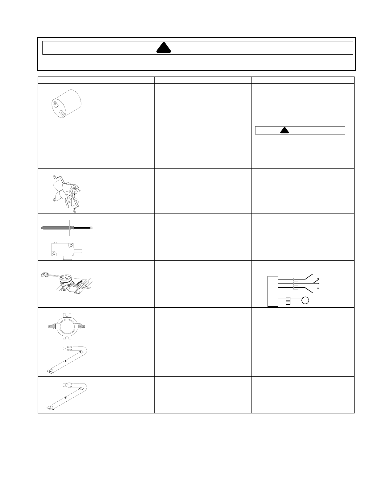
Illustration Component Test Procedure Results
Oven light socket Test continuity of receptacle terminals.
Measure voltage at oven light.
Indicates continuity with bulb screwed in.
120 VAC, see wiring diagram for terminal
identification.
If no voltage is present at oven light
Hinge Carefully open the hinge fully, and
insert a wooden dowel or screwdriver
bit into opening.
Remove top and bottom screws
securing hinge.
Slide hinge top towards rear of unit
check wiring.
CAUTI ON
!
Do not place hands in hinge area when
oven door is removed. Hinge can snap
closed and pinch hands or fingers.
and guide hinge out through frame
opening or storage drawer.
NC
NO
COM
Fan motor Verify supply voltage..........................
Disconnect and check continuity of
motor at the terminals ........................
Verify terminals are not shorted to
chassis...............................................
Temperature sensor Measure resistance.
Door light switch Switch connection in following
positions:
Not engaged
Engaged
Door latch assembly Disconnect wires and test for
continuity per diagram.
Refer to Parts Manual for correct
autolatch switch associated with the
correct manufacturing number.
Controls Verify proper operation.
Temp. Limit Switch.............................
Bake burner Verify gas is supplied.
120 VAC
Approximately 400 Ω
If shorted, replace.
Approximately 1100 Ω at room
temperature 75ºF.
Normally Open
COM-NO=Open, COM-NC=Closed
COM-NO=Closed, COM-NC=Open
M
Cam Switches
SW 1
(Lock) N.O .
Common
SW 2
(Unlock) N.C.
AC Motor
Wiring Diagram
C
O
N
T
R
O
L
Open at 230°F, Closes at 190°F
Orifice adjusted for Natural or LP.
Broil burner Verify gas is supplied.
Check for obstructions or
contamination in ports.
Verify proper orifice installed for
Natural or LP.
Check for damage to bracket.
Replace if punctured or torn.
© 2004 Maytag Services 16022514 Rev. 0
15
Testing Procedures
!
WARNING
To avoid risk of electrical shock, personal injury, or death, disconnect power to oven before servicing, unless
testing requires power.
Illustration Component Test Procedure Results
Pressure regulator Verify gas pressure (WCP).
Ignitor Test for voltage at terminals ...............
Gas valve Disconnect wiring to valve.
Shut off valve Check to verify gas supply is turned on
If on LP service, verify proper gas
supply conversion.
Test for the amount of amperage in the
circuit..................................................
(Ignitor may glow, but not have
sufficient amperage to open valve).
Measure resistance on bake circuit.
Measure resistance on broil circuit.
(shown in the OFF position).
" Natural
4
10
" LP/Propane
120 VAC
−3.6 Amps.
3.2
Continuity
WAR NI NG
!
Do not attempt to open valve with
120 VAC.
Verify valve does not leak.
Filter capacitor
16
16022514 Rev. 0
© 2004 Maytag Services

Testing Procedures
!
WARNING
To avoid risk of electrical shock, personal injury, or death, disconnect power to oven before servicing, unless
testing requires power.
Illustration Component Test Procedure Results
H1 Controlled Oven temperature
adjustment
H1 Controlled Temperature display Press and hold
H1 Controlled Clock Display Press and hold
H1 Controlled 24 Hour Clock Press and hold
H1 Controlled Factory Default Press and hold
H1 Controlled Twelve hour off Control will automatically cancel any
H1 Controlled Sabbath Mode Hold
H1 Controlled Child lock out Press and hold
H1 Controlled Diagnostic Code
Display
Press
BAKE
pad.
550
Enter
Immediately press and hold
pad for 3 seconds.
Oven can be adjusted from -35 to +35
degrees in 5-degree increments by
pressing
over adjusting the oven, move
temperature 5 degrees each time.
Wait 4 seconds for the data entry timer
to expire to accept the change.
Temperature adjustment will be
retained even through a power failure.
pads for 3 seconds.
pads for 3 seconds.
pads for 3 seconds.
Warm
cooking operation and remove all
relay drives 12 hours after the last pad
touch.
activate Sabbath mode.
Hold
Sabbath mode.
Hold
display where the temperature
normally appears.
To reactivate the control, press and
hold
for 3 seconds.
Press and hold
Power Up
Cycle through the codes using the
number pads 1 through 5.
on the digit-pad.
AUTOSET
pads for 3 seconds.
CLOCK
CLOCK
pads for 3 seconds. “OFF” will
Cancel
the unit.
pad. To avoid
Cancel
Cancel
Cancel
Cancel
button for 3 seconds to
for 3 seconds to disable
Cancel
and
Cook & Hold
0/Autoset
and
and
and
and
and
pad and
BAKE
Bake
Clock
Favorite
Keep
Cook &
pads
While increasing or decreasing oven
temperature, this does not affect selfcleaning temperature.
This mode enables the user to indicate
F° or C° on the display.
Allows clock to be toggled On or OFF.
Allows the time on the clock to be
toggled from 12 hour or 24 hour display.
Allows the clock to be reset to factory
settings.
See Sabbath mode to disable.
“88:88” will be displayed and flash for 5
seconds.
Display will go back to time of day.
All pad inputs are disabled except for
CANCEL and CLOCK pads.
This mode disables the normal 12 hour
shutoff to allow operation of the bake
mode for a maximum of 37 hours.
This is a safety feature that can be used
to prevent children from accidentally
programming the oven. It disables the
electronic oven control.
Child lockout features must be reset after
a power failure.
The last 5 diagnostic codes will be stored
in the non-volatile memory.
See “Description of Error Codes” for
explanation.
© 2004 Maytag Services 16022514 Rev. 0
17
Testing Procedures
!
WARNING
To avoid risk of electrical shock, personal injury, or death, disconnect power to oven before servicing, unless
testing requires power.
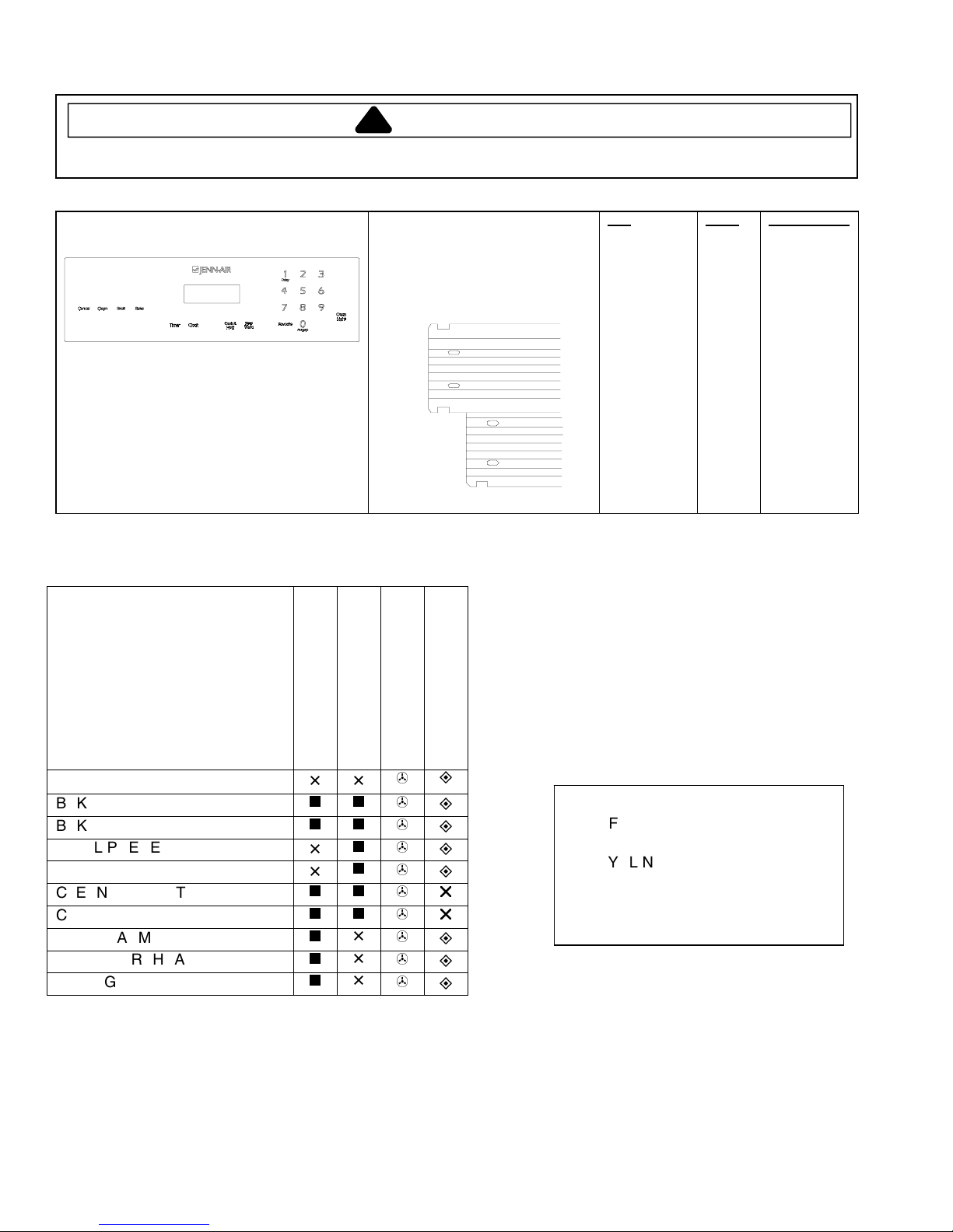
Jenn-Air Matrix
Control Panel Assembly
Continuity is indicated as follows:
1000 – 6600 Ω for Cancel pad
1000 – 15000 Ω for All other pads
16
9
8
1
Pad
1
2
3
4
5
6
7
8
9
0
Cancel
Clock
Cook & Hold
Broil
Bake
Clean
Keep Warm
Favorite
Timer
Oven Light
Trace
13 & 15
12 & 15
10 & 15
7 & 13
12 & 13
10 & 12
4 & 13
4 & 12
5 & 10
5 & 12
1 & 2/3
4 & 14
5 & 14
13 & 14
7 & 15
5 & 7
14 & 15
5 & 13
4 & 5
4 & 10
Measurement
Continuity
Continuity
Continuity
Continuity
Continuity
Continuity
Continuity
Continuity
Continuity
Continuity
Continuity
Continuity
Continuity
Continuity
Continuity
Continuity
Continuity
Continuity
Continuity
Continuity
Relay Logic
Note that this chart was correct at time of printing; subsequent changes to cooking parameters may alter it.
COOKING MODE
IDLE
BAKE PREHEAT
BAKE
BROIL PREHEAT
BROIL
CLEAN PREHEAT
CLEAN
KEEP WARM
DRYING PREHEAT
DRYING
BAKE
BROIL
COOLING FAN
r
r
18
16022514 Rev. 0
OVEN LIGHT
KEY INDEX
- OFF
- ON
- CYCLING
- ON OR OFF (DETERMINED BY
USER INPUT)
- TEMPERATURE CONTROLLED
© 2004 Maytag Services
 Loading...