

JENN-AIR JGS8850ADW, JGS8850ADS, JGS8850ADQ, JGS8850ADB, JGS8750ADW Installation Instructions
...
INSTALLER: LEAVE THESE INSTRUCTIONS WITH THE APPLIANCE
INSTALLATION MANUAL
Gas 30-inch Wide
Jenn-Air Expressions Range
PLEASE KEEP THIS MANUAL FOR FUTURE REFERENCE
THE MANUAL IS INTENDED TO ASSIST IN THE INITIAL INSTALLATION AND ADJUSTMENTS OF THE RANGE.
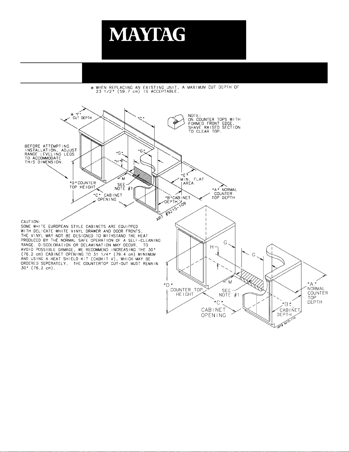
CLEARANCE DIMENSIONS
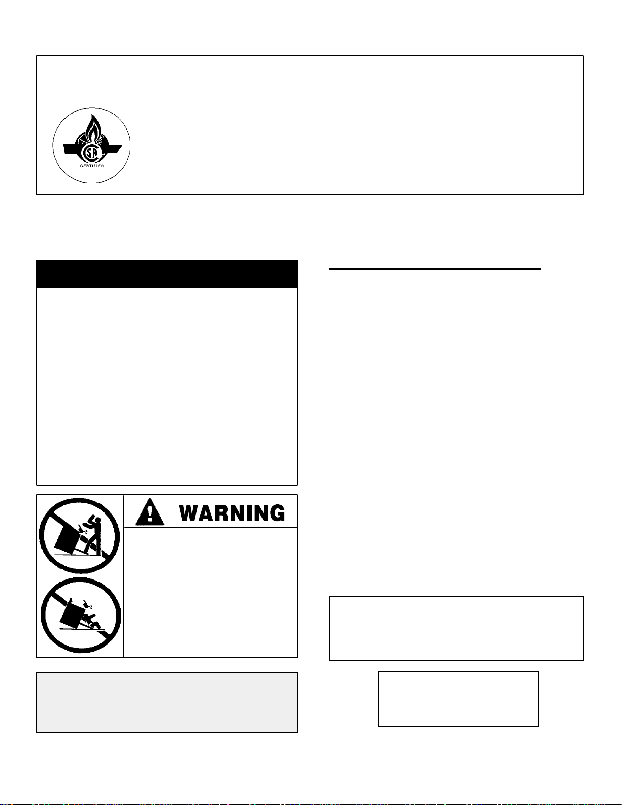
SPECIAL WARNING
Only qualified personnel should
install or service this range.
Read “Safety Instructions” in the
Use & Care book before using
range.
Improper installation, adjustment,
alteration, service, maintenance or
use of range can result in serious
injury or property damage.
Range may be installed with zero inches clearance
adjacent to (against) combustible construction at the
rear and on the sides below the cooktop. For complete
information in regard to the installation of wall cabinets
above the range and clearances to combustible wall
above the cooking top see the installation drawings. For
SAFETY CONSIDERATIONS do not install a range in
any combustible cabinetry which is not in accord with
the installation drawings.
*NOTE:30 inch dimension between cooking top and
wall cabinet shown on illustration does not apply to
ranges with an elevated oven. The 30 inch dimension
may be reduced to not less than 24 inches when the
wall cabinets in a domestic home are protected with
fireproof materials in accordance with American National
Standards - National Fuel Gas Code or in mobile homes
when they are protected with fireproof materials in
accordance with the Federal Standard for Mobile Home
Construction and Safety.
· ALL RANGES CAN TIP AND
CAUSE INJURIES TO
PERSONS.
· INSTALL ANTI-TIP DEVICES
PACKED WITH RANGE.
· FOLLOW ALL INSTALLATION
INSTRUCTIONS.
Your range may not be equipped
with some of the features referred
to in this manual.
To eliminate the risk of burns or fire by reaching over
heated surface units, cabinet storage space located
above the surface units should be avoided. If cabinet
storage is to be provided, the risk can be reduced by
installing a range hood that projects horizontally a
minimum of 5 inches beyond the bottom of the cabinets.
CAUTION: Some cabinets and building materials
are not designed to withstand the heat produced by
the normal safe operation of a listed appliance.
Discoloration or damage, such as delamination, may
occur.
ENGLISH '''' PP. 1-10
ESPAÑOL '''' pág. 11 -20
FRANCAIS '''' p. 21-30
8101P591-60
(05-04-00)
â
COM
·
Bring innovation home.t
30²
²
²²
JENN-AIR RANGES
FIGURE 1
FIGURE 2
Notes:
1. Provide for either a 3 -wire or 4-wire 120/208, 120/240 volt outlet per applicable cord in shaded area shown. Refer
to installation instructions for proper positioning of outlet. This is also the recommended gas line location.
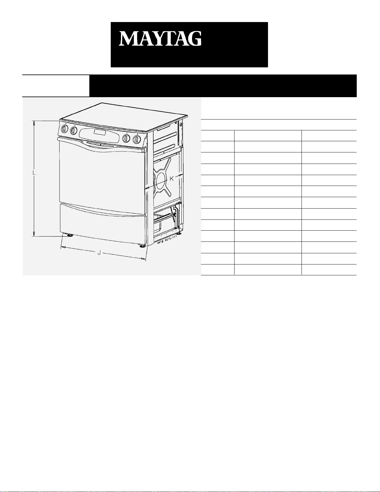
2. Dimension K (figure 3, page 3) is from the wall to the side edge of the oven door. It does not include the curvature
of the glass or the depth of the handle.
3. Dimension L (figure 3, page 3) is with the leveler legs adjusted all the way in. This may vary slightly upon leveling
leg adjustment.
4. Do not use grout, epoxy, etc., to install this unit. Installation must allow for removal of this appliance from the
installed location for purposes of servicing.
IMPORTANT: Because of continuing product improvements, Maytag reserves the right to change specifications
without notice. Dimensional specifications are provided for planning purposes only. For complete details see
installation instructions that accompany each product before selecting cabinetry, making cutouts or beginning
installation.
-2-
â
COM
·
Bring innovation home.t
30²
²
²²
FIGURE 3
JENN-AIR RANGES
Unity II Slide-In Range
Dimensions
JJJJ
A
B
C
D
E
F
G
H
J
2*
K
3*
L
M
* SEE NOTES ON PAGE 2
Inches
25
24
30
36
23 5/8
23 1/4
51/2
10
29 7/8
26 3/16
35 3/4
21/4
Centimeters
63.5
61.0
76.2
91.4
60.0
59.1
14.0
25.4
75.9
66.5
90.8
5.7
-3-
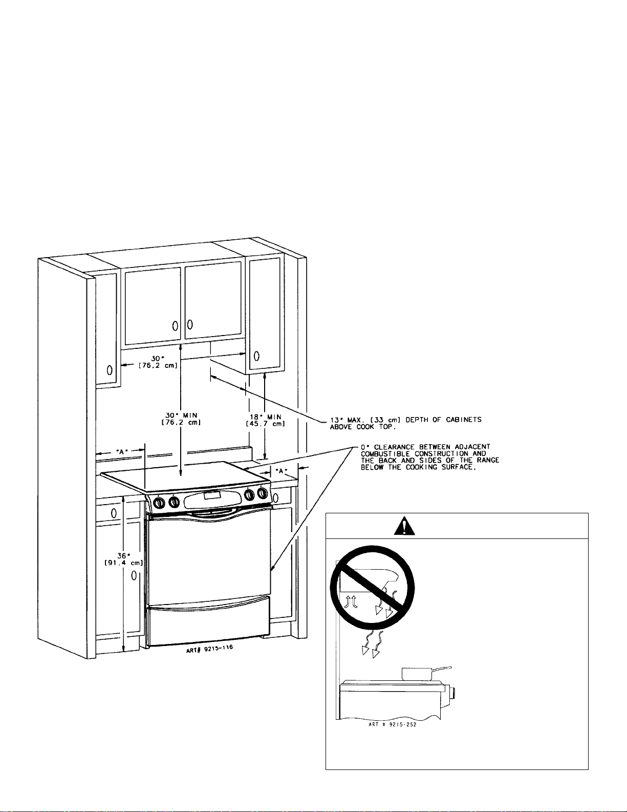
Dimension “A” is to be a minimum of 3-inches (7.5 cm).
Check the range model number plate to see if the range is
approved for installation in mobile homes and/or
recreational vehicles. If approved the following items are
applicable.
In Canada the range must be installed in accordance with
the current CSA Standard C22.1 - Canadian Electrical
Code Part 1 and Section Z240.4.1 - Installation
Requirements for Gas Burning Appliances in Mobile
Homes (CSA Standard CAN/CSA - Z240MH).
MOBILE HOMES
The installation of a range designed for mobile home
installation must conform with the Manufactured Home
Construction and Safety Standard, Title 24 CFR, Part
3280 [formerly the Federal Standard for Mobile Home
Construction and Safety, Title 24 HUD, (Part 280)] or,
when such standard is not applicable, the Standard for
Manufactured Home Installations, ANSI A225.1/NFPA
501A, or with local codes.
RECREATIONAL VEHICLES
The installation of a range designed for recreational
vehicles must conform with state or other codes or, in the
absence of such codes, with the Standard for
Recreational Vehicles, ANSI A119.2-latest edition.
In Canada the range must be installed in accordance with
CAN/CSA - Z240.6.2 - Electrical Requirements for R.V.’s
(CSA Standard CAN/CSA - Z240 RV Series) and Section
Z240.4.2 - Installation Requirements for Propane
Appliances and Equipment in R.V.’s (CSA Standard
CAN/CSA - Z240 RV Series).
LOCATING THE RANGE
Do not set range over holes in the floor or other locations
where it may be subject to strong drafts. Any opening in
the wall behind the range and in the floor under the range
should be sealed. Make sure the flow of combustion or
ventilation air is not obstructed.
NOTE: A range should NOT be installed over kitchen
carpeting.
FIGURE 4
WARNING
THIS PRODUCT SHOULD NOT
BE INSTALLED BELOW A
VENTILATION TYPE HOOD
SYSTEM THAT DIRECTS AIR IN
A DOWNWARD DIRECTION.
(SEE FIGURE)
THESE SYSTEMS MAY CAUSE
IGNITION AND COMBUSTION
PROBLEMS WITH THE GAS
BURNERS RESULTING IN
PERSONAL INJURY AND MAY
AFFECT THE COOKING
PERFORMANCE OF THE UNIT.
NOTE: THE FIGURE MAY NOT ACCURATELY REPRESENT YOUR
RANGE OR COOKTOP; HOWEVER, THIS WARNING APPLIES TO
ALL GAS COOKING PRODUCTS.
-4-
ANTI-TIP DEVICE INSTALLATION INSTRUCTIONS
NOTE: A risk of range tip over exists if the appliance is
not installed in accordance with the installation
instructions provided. The proper use of this device
minimizes the risk of TIP-OVER. In using this device the
consumer must still observe the safety precautions as
stated in the USE and CARE MANUAL and avoid using
the oven door and/or lower drawer as a step stool.
Installation instructions are provided for wood and cement
in either floor or wall. Any other type of construction may
require special installation techniques as deemed
necessary to provide adequate fastening of the ANTI-TIP
bracket to the floor or wall.
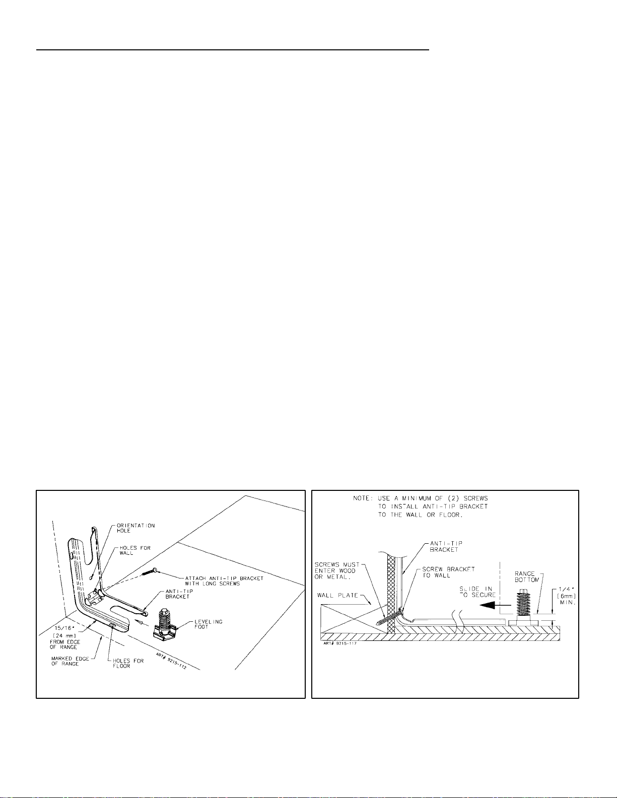
STEP 1 - Locating The Bracket (see figure 5)
A. Determine where either the right or left rear “edge” of
the range will be located and mark the floor or wall.
B. Place the BRACKET 15/16² from the marked “EDGE”
toward center of opening and against the back wall as
shown in figure 5.
C. Use the bracket as a template and mark the required
holes, as shown in figure 5 for the type of construction
you will be using.
STEP 2 - Anti-Tip Bracket Installation
A. Wood Construction:
1. Floor: Locate the center of the two holes identified
in figure 5 as “HOLES FOR FLOOR”. Drill a 1/8²
pilot hole in the center of each hole (a nail or awl
may be used if a drill is not available). Secure the
ANTI-TIP bracket to the floor with the two screws
provided. Proceed to STEP 3.
2. Wall: Locate the center of the two holes identified
in figure 5 as “HOLES FOR WALL. Drill an angled
1/8² pilot hole in the center of each hole as shown
in figure 6. (A nail or awl may be used if a drill is
not available). Secure the ANTI-TIP bracket to the
wall with the two screws provided as shown in
figure 6. Proceed to STEP 3.
B. Cement or Concrete Construction:
1. Suitablescrews for concrete construction can be
obtained at a hardware store. Drill the required
size hole for the screws obtained into the
concrete at the center of the holes identified in
figure 5 as “HOLES FOR FLOOR”. Secure the
ANTI-TIP bracket to the floor. Proceed to STEP 3.
STEP 3 - Range Installation
A. Align the range to its designated location and slide it
back into position. Make sure that the leveling foot is
fully inserted into and secured by the ANTI-TIP
bracket. Note: A minimum clearance of 1/4² is
required between the range and the leveling foot that
will engage the ANTI-TIP bracket, see figure 6.
B. For safety considerations as well as optimum
performance adjust the range so that it is level. This
may be checked by placing a spirit level or a large
pan of water on the cooktop or the oven rack.
Jenn-Air ranges require total removal from cabinet
before an adjustment can be made.
C. To check the range for proper installation of the
anti-tip bracket: Use a flashlight and look underneath
the bottom of the range to see that one of the rear
leveling legs is engaged in the bracket slot.
D. Proceed with the remainder of the installation
instructions.
FIGURE 5 FIGURE 6
-5-
CONNECTING THE RANGE
ELECTRIC SUPPLY
The appliance, when installed, must be electrically
grounded in accordance with local codes or, in the
absence of local codes, with the National Electrical Code,
ANSI/NFPA 70.
In Canada the range must be installed in accordance with
the current CSA Standard C22.1 - Canadian Electrical
Code Part 1.
ELECTRICAL SUPPLY CONNECTION:
The range requires 120 volts, 60 cycle alternating current
from an outlet. See serial plate for rating.
User may experience occasional circuit tripping if Ground
Fault Circuit Interrupter (GFCI) outlet or breaker is in use.
WARNING
Electrical Grounding Instructions
This appliance is equipped with a (three-prong)
grounding plug for your protection against shock
hazard and should be plugged directly into a
properly grounded receptacle. Do not cut or remove
the grounding prong from this plug.
WARNING
DISCONNECT ELECTRICAL SUPPLY
BEFORE SERVICING THE APPLIANCE.
In The Commonwealth Of Massachusetts
This product must be installed by a licensed plumber or
gas fitter when installed within the Commonwealth of
Massachusetts.
A “T” handle type manual gas valve must be installed in
the gas supply line to this appliance.
A flexible gas connector, when used, must not exceed a
length of three (3) feet / 36 inches.
GAS SUPPLY
Installation of this range must conform with local codes or,
in the absence of local codes, with the National Fuel Gas
Code, ANSI Z223.1-latest edition.
In Canada the range must be installed in accordance with
the current CGA Standard CAN/CGA-B149 - Installation
Codes for Gas Burning Appliances and Equipment and/or
local codes.
GAS SUPPLY CONNECTION: (See figure 7)
A QUALIFIED SERVICEMAN OR GAS APPLIANCE
INSTALLER MUST MAKE THE GAS SUPPLY
CONNECTION. Leak testing of the appliance shall be
conducted b y the installer according to the
instructions given in section h.
NATURAL GAS SUPPLY LINE MUST HAVE A NATURAL
GAS SERVICE REGULATOR. INLET PRESSURE TO
THIS APPLIANCE SHOULD BE REDUCED TO A
MAXIMUM OF 14 INCHES WATER COLUMN (0.5
POUNDS PER SQUARE INCH (P.S.I.) LIQUEFIED
PETROLEUM (L.P.)
MUST HAVE A L.P. GAS PRESSURE REGULATOR.
INLET PRESSURE TO THIS APPLIANCE SHOULD BE
REDUCED TO A MAXIMUM OF 14 INCHES WATER
COLUMN (0.5 P.S.I.). INLET PRESSURES IN EXCESS
OF 0.5 P.S.I. CAN DAMAGE THE APPLIANCE
PRESSURE REGULATOR AND OTHER GAS
COMPONENTS IN THIS APPLIANCE AND CAN
RESULT IN A GAS LEAK.
a. AGAS CUTOFF VALVE SHOULD BE PUT IN AN
ACCESSIBLE LOCATION IN THE SUPPLY LINE
AHEAD OF THE RANGE, FOR TURNING ON AND
TURNING OFF GAS SUPPLY. If range is to be
connected to house piping with flexible or semi-rigid
metal connectors for gas appliances, CONNECTOR
NUTS MUST NOT BE CONNECTED DIRECTLY TO
PIPE THREADS. THE CONNECTORS MUST BE
INSTALLED WITH ADAPTORS PROVIDED WITH
THE CONNECTOR.
b. The house piping and/or range connector used to
connect the range to the main gas supply must be
clean, free of metal shavings, rust, dirt and liquids (oil
or water). Dirt, etc. in the supply lines can work its
way into the range manifold and in turn cause failure
of the gas valves or controls and clog burners and/or
pilot orifices.
CAUTION: DO NOT LIFT OR MOVE RANGE BY
DOOR HANDLES, OR BACKGUARD.
c. Turn off all pilots and main gas valve of other gas
appliances.
d. Turn off main gas valve at meter.
e. Before connecting range, apply pipe thread
compound approved for LPG to all threads.
f. Connect range to gas supply at appliance pressure
regulator using adaptors supplied with flexible
connector. Rigid pipe may also be used. See rating
plate for type of gas range has been manufactured
for.
g. Turn on main gas valve at meter, and relight pilots at
other gas appliances.
h. Apply a non-corrosive leak detection fluid to all joints
and fittings in the gas connection between the supply
line shut-off valve and the range. Include gas fittings
and joints in the range if connections were disturbed
during installation. Check for leaks! Bubbles
appearing around fittings and connections will indicate
a leak. If a leak appears, turn off supply line gas
shut-off valve, tighten connections, turn on the supply
line gas shut off valve, and retest for leaks.
CAUTION: NEVER CHECK FOR LEAKS WITH A
FLAME.
WHEN LEAK CHECK IS COMPLETE, WIPE OFF
ALL RESIDUE.
/PROPANE GAS SUPPLY LINE
-6-
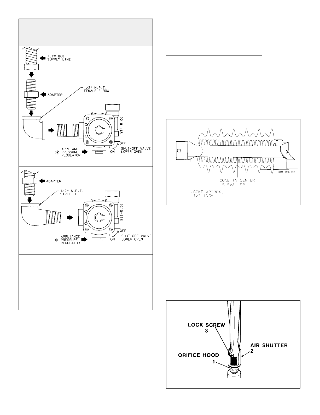
Gas Supply Connections For Ranges With
Appliance Pressure Regulator
Located In The Bottom Of Range
TO CONNECT GAS SUPPLY TO 1/2² N.P.T. MALE INLET
valve during any pressure testing of the gas supply
piping system at test pressures equal to or less than
1/2 lbs./sq. in. (3.5 kPa) (13.8 in. water column).
RANGE ADJUSTMENTS
Top Section - Electric Ignition
To operate, push and turn top burner knob to the LITE
position. The top burner will light. To turn OFF spark after
the top burner has ignited turn knob to HI setting.
Air Shutter - Oven Burner
a. The approximate length of the flame of oven burner is
a 1/2 inch distinct inner blue flame, figure 7.
TO CONNECT GAS SUPPLY TO 1/2² N.P.T. FEMALE INLET
FIGURE 7
WHEN THE INSTALLER HAS COMPLETED
INSTALLATION OF THE APPLIANCE, LEAVE THE
APPLIANCE PRESSURE REGULATOR SHUT-OFF
VALVE IN THE “ON”
POSITION.
* The appliance pressure regulator on your range may
differ from this illustration.
CHECKING PRESSURE OF HOUSE PIPING
SYSTEM
1. The appliance and its individual shutoff valve must be
disconnected from the gas supply piping system during
any pressure testing of that system at test pressures in
excess of 1/2 lbs./sq. in. (3.5 kPa) (13.8 in. water
column).
FIGURE 8
b. Oven burner flame can be checked as follows:
1. Yellow flame on burner - open burner air shutter
to the widest opening that will not cause the flame
to lift or blow off the burner when cold. (See #2 on
figure 8).
2. Distinct blue flame but lifting - close burner air
shutter to the point where it will not cause the
flame to lift or blow off the burner when cold. (See
#2 on figure 8).
c. The oven burner air shutter adjustment is the same on
ranges with a gas pilot or electric ignition.
2. The appliance must be isolated from the gas supply
piping system by closing its individual manual shutoff
FIGURE 9
-7-
GAS CONVERSION
General
All ranges and cooktops are equipped with double coaxial
(universal) orifices and with a convertible appliance
pressure regulator. The unit model number plate states
which gas it was adjusted for at the factory. To convert the
unit to either Natural gas or LP gas will require adjustment
of the orifice hoods, air shutters on the burners and
adjustment of the appliance pressure regulator converter
cap.
Inlet pressure to the appliance pressure regulator should
be as follows for both operation and checking of appliance
pressure regulator setting:
INLET PRESSURE IN NATURAL LP
INCHES OF WATER COLUMN
Minimum 6 11
Maximum 14 14
GAS GAS
WARNING
Gas leaks may occur in your system and result in a
dangerous situation. Gas leaks may not be detected by
smell alone. Gas suppliers recommend youpurchase and
install an UL approved gas detector. Install and use in
accordance with the manufacturer’s instructions.
Appliance Pressure Regulator Conversion
The unit appliance pressure regulator must be set to
match the type gas supply used. If converting from natural
gas to LP gas, the appliance pressure regulator must be
converted to regulate LP gas. If converting from LP gas to
natural gas, the appliance pressure regulator must be
converted to regulate natural gas.
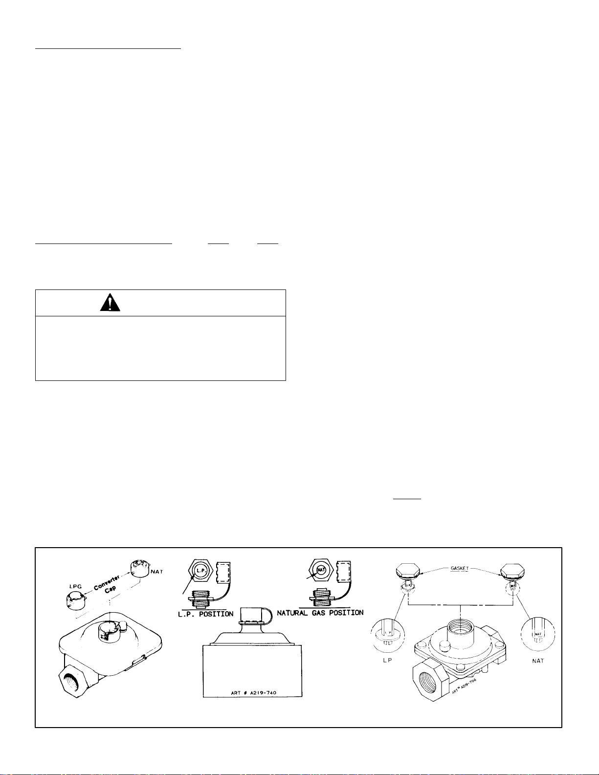
To convert the appliance pressure regulator from one gas
to another, do either (1), (2) or (3) below: Your unit will be
equipped with one of the three appliance pressure
regulator types shown below.
1. Remove the cap, push down and turn
counter-clockwise. Turn the cap over and reinstall
(figure 10).
NOTE: The gas type you are converting to must be
visible on the top of the installed appliance pressure
regulator cap.
2. Remove plastic dust cover from cap nut on top of
appliance pressure regulator. Remove cap nut from
appliance pressure regulator (plastic dust cover comes
off with nut). “IMPORTANT” remove plastic dust cover
from cap nut and reinstall on opposite side of cap nut.
Reinstall cap nut to appliance pressure regulator and
replace dust cover. “CAUTION” be sure marking for
the type of gas to which appliance pressure regulator
has just been converted is visible in top of cap nut
before replacing plastic dust cover. (See figure 11).
3. Remove cap and forcibly snap out plastic plunger from
bottom of cap. Turn plunger over and forcibly snap
back in original location (figure 12).
NOTE: Plunger MUST
you are converting to must be visible on lower side of
plunger.
FIGURE 10 FIGURE 11 FIGURE 12
snap into position; the gas type
-8-
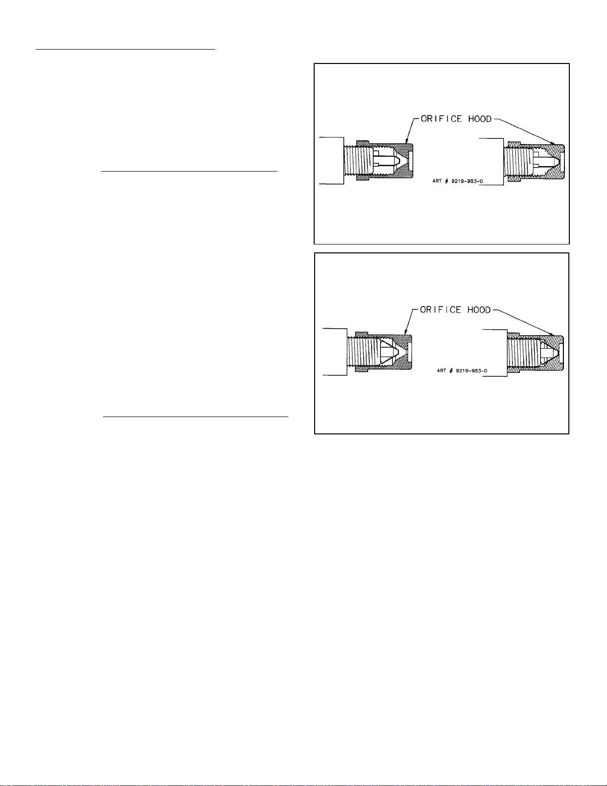
ORIFICE CONVERSION
1. From Natural Gas To LP/Propane Gas:
a. Change the appliance pressure regulator from
natural to LP setting. (See figures 10, 11 or 12).
b. Screw the burner orifice hoods down tight against
the pins. (See figure 13B). Use care to not over
tighten. Over tightening can damage the coaxial
pin inside the orifice hood.
NOTE: On units using Eaton Oven Safety Valve
screw the valve orifice hood down tight against the
valve body. (See figure 13D). It is important that
the hood be turned down as far as it can go to
insure that complete conversion has occurred.
c. Adjust burner air shutter to the widest opening that
will not cause the flame to lift or blow off the burner
when cold.
NOTE: Correctly adjusted sealed burners, can
have flames that will lift or blow without a pot over
the burner. These should be adjusted with a pot in
place.
2. From LP/Propane Gas To Natural Gas:
a. Change the appliance pressure regulator from LP
to natural setting. (See figures 10, 11 or 12).
FOR ALL TOP BURNER AND
OVEN SAFETY VALVE CONVERSION
(EXCEPT EATON VALVE)
,
FIGURE 13A
NATURAL GAS
SETTING
FOR EATON
OVEN SAFETY VALVE CONVERSION
FIGURE 13B
LP GAS
SETTING
b. Screw the burner orifice hoods away from the pins.
(See figure 13A). Approximately 1 1/2 to 2 turns.
NOTE: On units using Eaton Oven Safety Valve
screw the burner orifice hoods away from pin (see
figure 13C). Approximately 1 1/2 to 2 turns.
c. Adjust burner air shutter to the widest opening that
will not cause the flame to lift or blow off the burner
when cold.
NOTE: Correctly adjusted sealed burners, the
flame will lift or blow without a pot over the burner.
These should be adjusted with a pot in place.
FIGURE 13C
,
NATURAL GAS
SETTING
FIGURE 13D
LP GAS
SETTING
High Altitude Notice
The specified gas burner ratings typically apply to
elevations up to 2000 feet. For higher altitudes, the rates
may need to be reduced to achieve satisfactory operation.
A local certified gas servicer will be able to advise if a
reduction is necessary.
-9-
 Loading...