


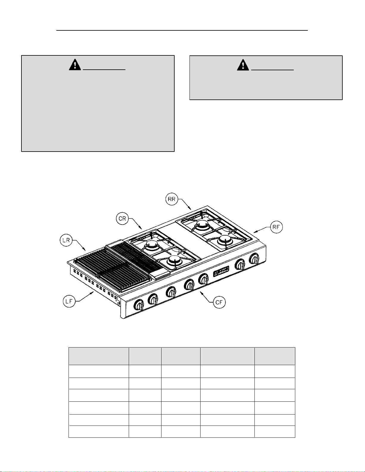
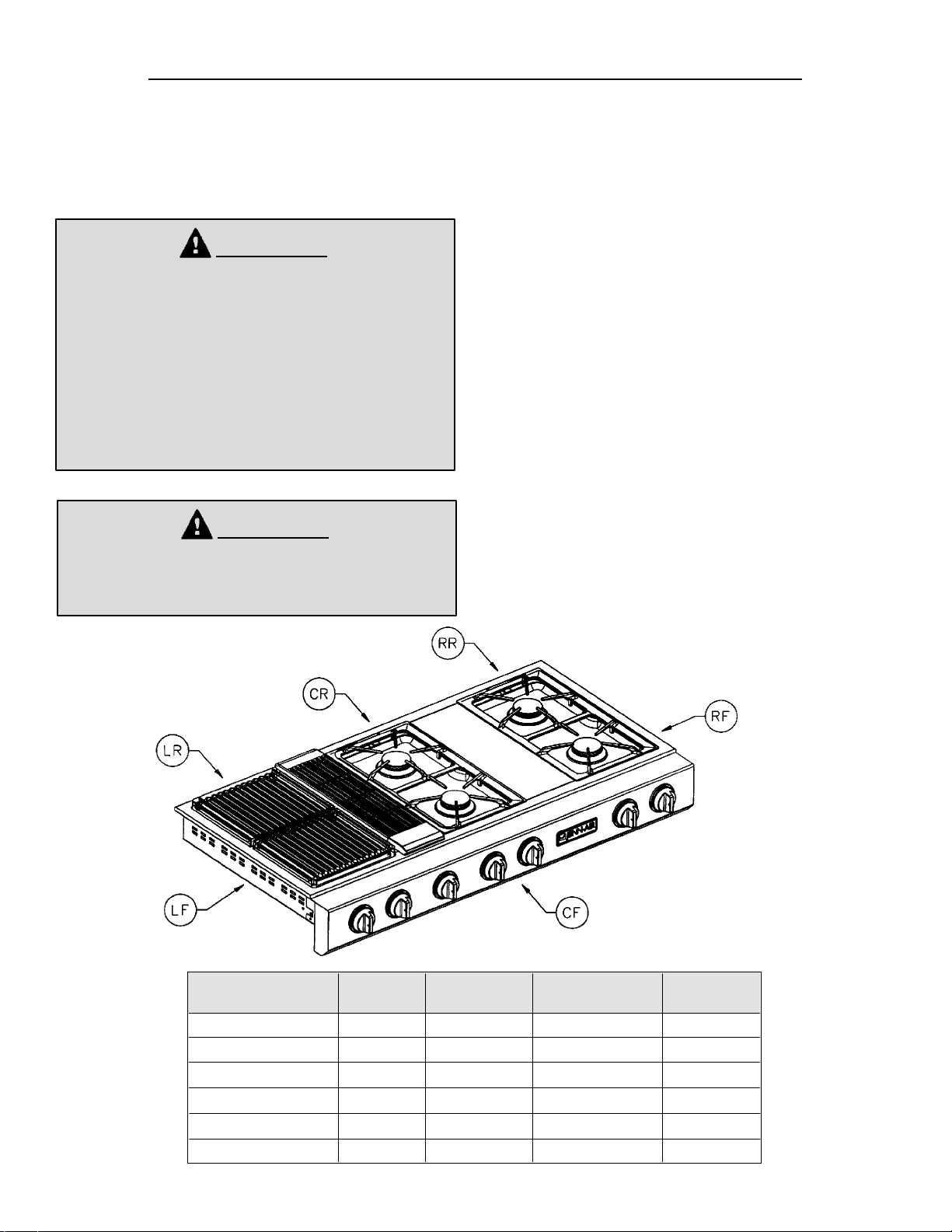
INSTALLATION
INSTRUCTIONS
NOTICE TO INSTALLER: Leave these instructions with the appliance.
NOTICE TO CONSUMER: Retain these instructions for future reference.
Triple Bay Conventional Gas
J
Prostyle
Model JGD8348BDP
Dimensions shown in both inches and centimenters
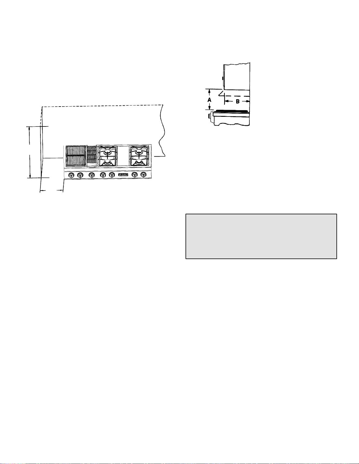
J Grill Cooktop
JJ
403 WEST FOURTH STREET, NORTH D NEWTON, IA 50208
* Blower may be
rotated for horizontal
or vertical direction by
loosening nuts
around blower inlet.
Accessible inside
ventilation chamber.
SELECT APPROPRIATE
DUCT CUTOUT
(SEE DUCTING
INSTALLATION INSTRUCTIONS.)
INSTRUCTIONS TO INSTALLER:
S Dimension “A” - provide 2² min. (5.08 cm) cabinet clearance to motor for cooling purpose.
S NOTE: Where possible, 6² (15.54 cm) is recommended for motor/blower service.
S Side Clearance: Grills installed near a side wall must allow a minimum clearance of
8² (20.32 cm).
S Access must be provided to remove and empty grease container.
8101P399-60
(09-01-00)
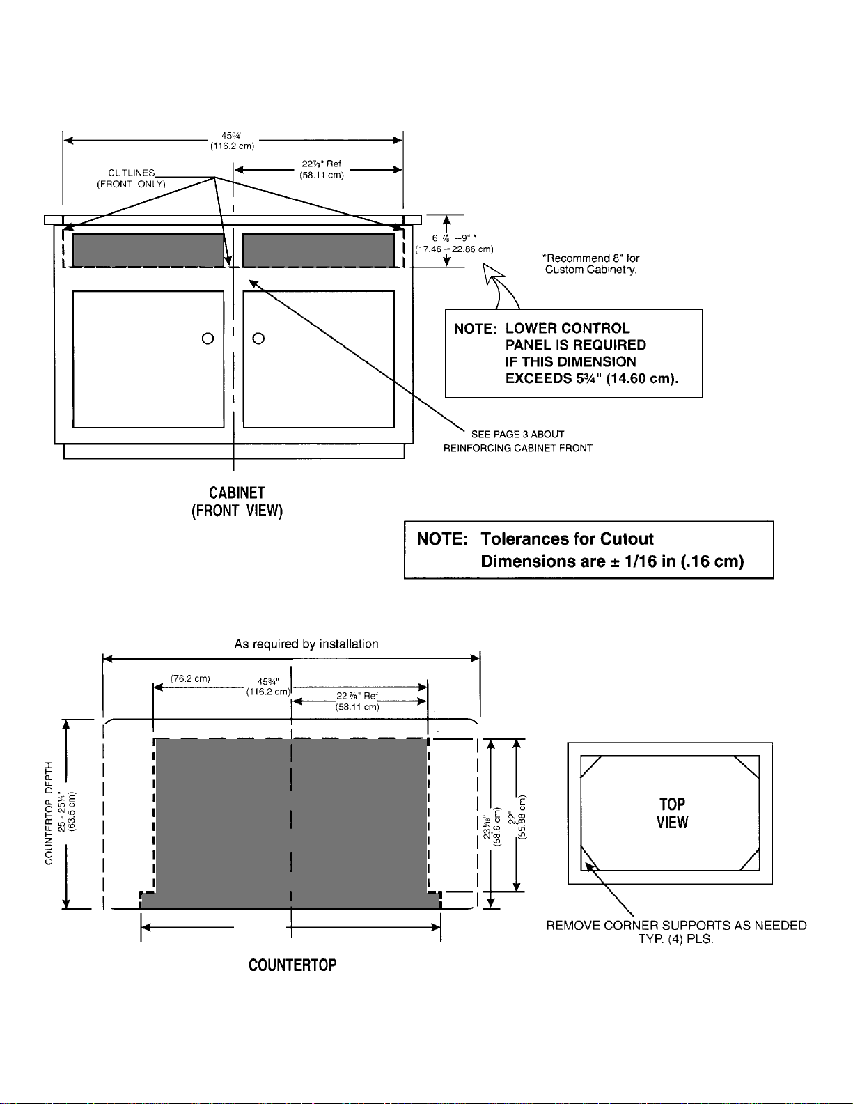
CABINET and COUNTERTOP CUTOUTS
EXISTING
OPENING
EXISTING
OPENING
See cutout suggestions 1-4 on page 6.
COUNTERTOP
CUTOUT
AREA
46 13/16²
(118.90 cm)
2
Installing Cabinetry Over Your
Jenn-Air Grill
Minimum horizontal clearance between the edge of the
appliance and combustible construction extending from
the cooking surface to 18² (45.7 cm) above the cooking
surface is:
:² (4.45 cm) at rear
1
8² (20.32 cm) at sides
NOTE: This is not the recommended clearance, but
minimum allowable clearance.
18²
(45.7 cm)
Avoid use of cabinets above cooktop for storage space to
eliminate associated potential hazards such as reaching
over open flames.
Dotted lines indicate range
hood construction.
* To eliminate the risk of burns or fire by reaching over
heated surface units, cabinet storage space located
above the surface units should be avoided. If cabinet
storage is to be provided, the risk can be reduced by
installing a range hood that projects horizontally a
minimum of 5 inches beyond the bottom of the
cabinets.
8²
(20.3 cm)
MIN. CLEARANCE
*A = 30² (76.2 cm) minimum vertical clearance
between cooking surface and construction above
the appliance.
B=13² (33.02 cm) maximum depth of cabinets
installed above cooking top.
Cabinets Above Cooking Top
Maximum depth of cabinets installed above cooking top is
13 inches.
CAUTION: SOME CABINETS AND BUILDING
MATERIALS ARE NOT DESIGNED TO WITHSTAND
THE HEAT PRODUCED BY THE NORMAL SAFE
OPERATION OF A LISTED APPLIANCE. DISCOLORATION OR DAMAGE, SUCH AS DELAMINATION, MAY OCCUR.
3
Installation Of Appliance
Follow accompanying ducting instructions carefully.
This appliance is designed to always be vented outdoors.
NOTE: For some cabinet styles, it may be necessary to
reinforce the front of the cabinet by attaching a brace
from front to rear inside the cabinet under the Burner Box.
The Countertop Cutout, Cabinet Front Cutout and Duct
Opening should be prepared according to the illustration
on pages 1 and 2.
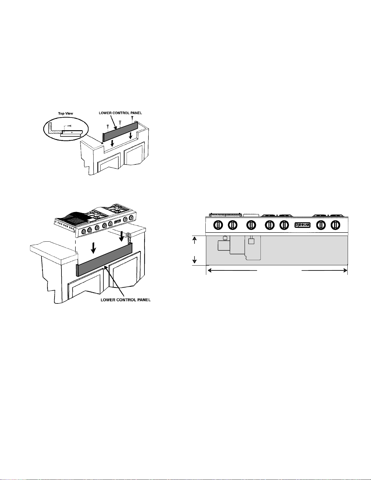
Install the Lower Control Panel in the bottom of the
Cabinet Cutout as shown using screws from Hardware
pack. (Figure 1).
Figure 1
Position unit in the Countertop Cutout. Main Control Panel
should overlap top of Lower Control Panel as shown.
(Figure 2).
Install ductwork per ducting instructions provided. Duct
openings in cabinet are shown in the drawing on page 1.
Make electrical and gas connections as described below
in this section of the instructions.
The installation of this appliance must conform with local
codes or, in the absence of local codes, with the latest
edition of the National Fuel Gas Code, ANSI Z.223.1 USA
or current CAN/CGA-B149 INSTALLATION CODE.
The electrical supply required is 110/120-volt, A.C., 15
amp, 60 Hz. This appliance is equipped with a grounded
type power cord. A grounded outlet must be provided. It is
recommended, for convenience, this outlet be located in
the area shown in the shaded illustration. This appliance,
when installed, must be electrically grounded in
accordance with local codes or, in the absence of local
codes, with the latest edition of the National Electrical
Code ANSI/NFPA No. 70 USA or current CSA
STANDARD C22.1 Canadian Electrical Code part 1.
Figure 2
10 1/16²
(25.56 cm)
46 13/16² (118.90 cm)
Servicing Cooktop
When servicing cooktop it is necessary to remove the
main top, prior to removing the control panel.
4
Connecting Appliance To Gas Supply
A TRAINED SERVICEMAN OR GAS APPLIANCE
INSTALLER MUST MAKE THE GAS SUPPLY
CONNECTION. Leak testing of the appliance shall be
conducted by the installer according to the instructions
given.
Air Shutter Adjustment
This appliance is shipped from the factory with air shutters
adjusted for use with Natural Gas. If further adjustment is
necessary, or to reset for use with LP, adjust air shutters as
follows:
Install a manual shutoff valve in an accessible location in
the gas line external to this appliance for the purpose of
turning on or shutting off gas to the appliance.
Make the gas connection to the inlet of the appliance
pressure regulator on this appliance with a 1/2² male pipe
thread. Use an approved pipe joint compound resistant to
the action of LP gas at pipe connections. Test all joints for
gas leaks with a soap and water solution or other
accepted leak detection means. Never test for gas leaks
with an open flame.
CAUTION: WARRANTY IS VOID ON JENN-AIR
EQUIPMENT INSTALLED OTHER THAN AS
RECOMMENDED BY MANUFACTURER. RECOMMENDED WALLCAPS ANDTRANSITIONS MUSTBE
UTILIZED FOR PROPER OPERATION AND INSTALLATION.
WARNING
ELECTRICAL GROUNDING INSTRUCTIONS
THIS APPLIANCE IS EQUIPPED WITH A THREEPRONG GROUNDING PLUG FOR YOUR
PROTECTION AGAINST SHOCK HAZARD AND
SHOULD BE PLUGGED DIRECTLY INTO A
PROPERLY GROUNDED RECEPTACLE. DO NOT
CUT OR REMOVE THE GROUNDING PRONG FROM
THIS PLUG.
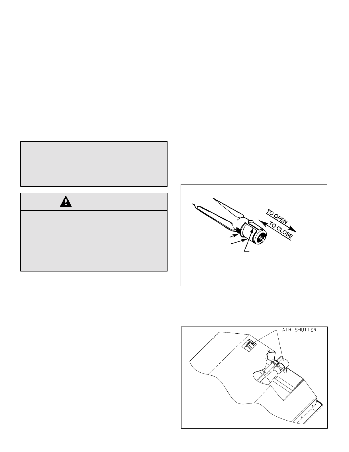
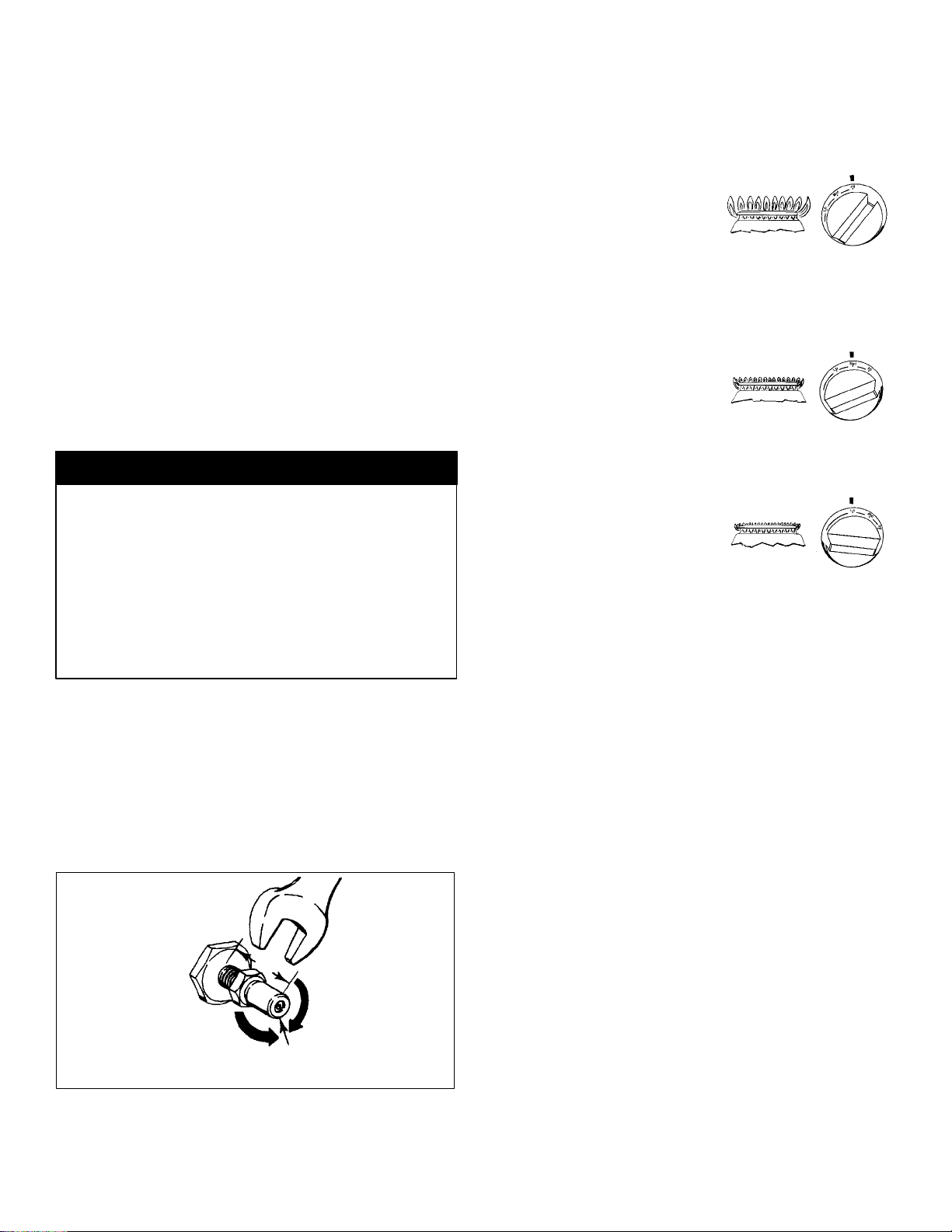
Grill Burner and Surface Burner
Cartridge Air Shutters
(See Illustrations “A” & “B”)
The left hand air shutter controls the rear half of the burner.
The right hand shutter controls the front half. Access to air
shutters on the surface burner cartridge may be found
through openings on the bottom of the cartridge housing.
Slide air shutters backward or forward to increase or
decrease the size of the air opening. Air shutters fit snugly,
soascrewdriver bladeor needle nose pliersmay berequired
to make this adjustment (see illustration).
Observe change in flame appearance as the air shutter is
moved. Adjustment is satisfactory when a clearly defined,
even blue flame results at the high flame setting. The snug
fitof theairshutter assuresit will remainpositionedcorrectly.
Grill Burner Air Shutter and Surface Burner
(if so equipped)
AIR OPENING
AIR SHUTTER
INSERT SCREWDRIVER
BLADE IN SLOT AND TWIST
WITH SLIGHT PRESSURE TO
ALLOW AIR SHUTTER TO
SLIDE EASILY
Illustration “A”
On any burner, closing the air shutter too far will cause the
flame to become soft and yellow tipped. Opening the air
shutter too wide will cause the flame to blow away from the
burnerports. Properadjustment willproduceasharp,clearly
defined, even blue flame.
Illustration “B”
5
Important Installation Suggestions
1. Chamfer all exposed edges of decorative laminate to
prevent damage from chipping.
2. Radius corners of cutout and file to insure smooth
edges and prevent corner cracking.
3. Rough edges, inside corners which have not been
rounded and forced fits can contribute to cracking of the
countertop laminate.
4. Countertop must be supported within 3² of cutout.
On any burner, closing the air shutter too far will
cause the flame to become soft and yellow tipped.
Opening the air shutter too wide will cause the flame
to blow away from the burner ports. Proper adjustment
will produce a sharp, clearly defined, even blue flame.
Pressure Testing
The maximum gas supply pressure for the appliance
pressure regulator supplied on this appliance is 14² W.C.
The test pressure for checking this appliance pressure
regulator must be at least 6² W.C. for Natural Gas, and at
least 11² W.C. for LP. It is shipped from the factory set for
Natural Gas at 5² W.C.
This appliance and its individual shutoff valve must be
disconnected from the gas supply piping system during
any pressure testing of that system at test pressures in
excess of 1/2² PSIG (3.5 k Pa).
This appliance must be isolated from the gas supply
piping system by closing its individual manual shutoff
valve during any pressure testing of the gas supply piping
system at test pressures equal to or less than 1/2² PSIG
(3.5 k Pa).
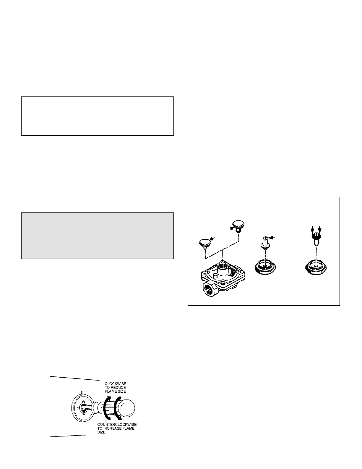
Low Flame Adjustment
(See Illustration “C”)
This appliance is shipped from the factory with low and
medium flame settings adjusted for use with Natural Gas.
If further adjustment is necessary, or to re-adjust for use
with LP, proceed as follows:
1. Light burner and set control knob for low flame.
2. Remove control knob from valve stem.
CAUTION: NEVER USE A METAL BLADE TO PRY
KNOB OFF. IF KNOB CANNOT BE EASILY
REMOVED, TUCK THE FOLDS OF A CLOTH
DISHTOWEL UNDER THE KNOB AND PULL THE
TOWEL UPWARD WITH STEADY, EVEN PRESSURE.
3. Insert a slender, thin-blade screwdriver into the recess
at center of valve stem and engage blade with slot in
adjusting screw.
4. Turn center stem adjusting screw to set flame size.
...clockwisetoreduce.
...counterclockwise to increase.
5. Replace control knob when adjustment is completed.
Appliance Pressure Regulator
Conversion
(See Illustration “D”)
This unit is supplied with a Maxitrol Appliance Pressure
Regulator. Follow the instructions in illustration “D”.
MAXITROL APPLIANCE PRESSURE REGULATOR
APPLY DOWNWARD
FINGER PRESSURE
AT DISC EDGES TO
REPLACE PIN IN CAP
APPLY
SIDEWARD
FINGER
PRESSURE TO
REMOVE PIN
FROM CAP
NAT
CONVERTER
CAP
AND PIN
LP
NAT LP
Illustration “D”
Proper adjustment will produce a stable, steady blue flame
of minimum size. The final adjustment should be checked
by turning knob from high to low several times without
extinguishing the flame.
This adjustment, at low setting, will automatically provide
the proper flame size at medium setting.
Illustration “C”
6
Conversion To LP Gas
This appliance is shipped from the factory equipped for
use with Natural Gas. To convert it from Natural Gas for
use with LP Gas, perform steps 1 through 4.
1. Remove Natural Gas orifice hoods. Install color coded
orifice hoods supplied. Located in a pack attached to
the outer plenum area of this appliance.
(See Illustration “E”, below, and LP Gas Conversion
instructions page 8).
2. Invert cap in convertible pressure regulator (if so
equipped) located at entrance to gas manifold.
3. Adjust air shutters on individual burners for proper
flame appearance.
4. Adjust low flame setting at each burner by turning
adjustment screw in center of valve stem.
To make these conversions adjustments follow the
instructions and illustrations (“A” through “E”, pages
5-7).
IMPORTANT
Apply a non-corrosive leak detection fluid to all joints
and fittings in the gas connection between the supply
line shut-off valve and the range. Include gas fitting
and joints in the range if connections were disturbed
during installation. Check for leaks! Bubbles appearing
around fittings and connections will indicate a leak. If a
leak appears, turn off supply line gas shut-off valve,
tighten connections, turn on the supply line gas shut
off valve, and retest for leaks. Never test for gas leaks
with an open flame.
Control Settings
The size and type of cookware and the amount and type
of food being cooked will influence the setting needed for
best cooking results. The setting indicated should serve as
a guide while you become familiar with your cooktop.
Use the HI flame setting to
quickly bring foods to a boil or to
begin a cooking operation. Then
reduce to a lower setting to
continue cooking. Never lease
food unattended over a HI flame
setting.
Med setting is used to continue a
cooking operation. Food will not
cook any faster when a HI flame
setting is used than that needed
to maintain a gentle boil.
Remember, water boils at the
same temperature whether boiling
gently or vigorously.
Use LO setting to keep food at
serving temperatures without
further cooking You may find that
some cooking may take place if
the cookware is covered.
This appliance is shipped from the factory with orifice
hoods drilled for use with Natural Gas. To convert from
Natural Gas to LP, apply a 1/2² open-end wrench to hex
section of orifice hood. Turn counterclockwise to remove.
Save the Natural Gas orifice hoods just removed from this
appliance for future use. Install color coded orifice hoods
supplied. (See LP Gas Conversion instructions above and
page 8). Turn clockwise to install. Hold dimension
specified in illustration “E”.
1/2² OPEN END
WRENCH
11/16²²²²
TURN
CLOCKWISE
COUNTERCLOCKWISE
TURN
TO REMOVE
ORIFICE HOOD
TO TIGHTEN
Illustration “E”
7
TO CONVERT APPLIANCE FOR USE WITH PROPANE GAS
Natural Gas To Propane Gas (LP) Conversion Instructions
WARNING
Propane Gas conversion is to be performed by
a Jenn-Air Authorized Service Contractor (or
other qualified agency) in accordance with the
manufacturer’s instructions and all codes and
requirements of the authority having
jurisdiction. Failure to follow instructions could
resultin serious injury or property damage.The
qualifiedagency performing this work assumes
responsibility for this conver sion.
WARNING
ELECTRICAL POWER AND GAS MUST BE
TURNED OFF PRIOR TO CONVERSION
Models - JGD8348BDP
Manifold - Propane Gas pressure required - 10² W.C.
Incoming Propane Gas pressure required to appliance
pressure regulator - 11² -12² W.C.
Propane Conversion Orifice Hoods are supplied with this
model.
Propane Gas input specified - 46,000 BTU/hr.
JGD8348BDP
INCHES
BURNER BTU/hr ORIFICE DIAMETER COLOR
Left Rear (LR) 7500 #66 .033 Zinc
Left Front (LF) 7500 #66 .033 Zinc
Center Rear (CR) 6500 #68 .031 Red
Center Front (CF) 9000 #63 .037 Blue
Right Rear (RR) 6500 #68 .031 Red
Right Front (RF) 9000 #63 .037 Blue
8
TO CONVERT APPLIANCE FOR USE WITH NATURAL GAS
Propane Gas (LP) To Natural Gas
Conversion Instructions
If this appliance has been converted for use with LP Gas,
each of the following modifications must be performed to
convert the unit back to Natural Gas.
WARNING
NaturalGasconversion isto be performed by a
Jenn-Air Authorized Service Contractor (or
other qualified agency) in accordance with the
manufacturer’s instructions and all codes and
requirements of the authority having
jurisdiction. Failure to follow instructions could
resultin serious injury or property damage.The
qualifiedagency performing this work assumes
responsibility for this conver sion.
WARNING
ELECTRICAL POWER AND GAS MUST BE
TURNED OFF PRIOR TO CONVERSION
Model - JGD8348BDP
Manifold - Natural Gas pressure required - 5² W.C.
Incoming Natural Gas pressure required to appliance
pressure regulator - 6² -7² W.C.
Natural Gas input specified - 56,000 BTU/hr.
A. Replaceall orifice hoods - Performsteps 1through 4 on
page7.Locatethe (6)sixNaturalGas hoods(withsmall
numbersstamped on theirsides savedfrom theoriginal
Natural Gas unit). Page 5 Illustration “E”. The two
hoods with .0520 (#55 orifice) stamped on them are for
the left front and left rear burners. The four hoods with
the .0595 (#53 orifice) stamped on them are for the two
right burners.
To make these conversion adjustments follow the
instructionsand illustrations (“A”through “E”) pages
5-7.
B. Invert cap in appliance pressure regulator (see
Illustration “D”, page 6). With the appliance installed,
the appliance pressure regulator is located on the right
underside of the appliance at the inlet to the gas
manifold. Identify the type of appliance pressure
regulator on the unit and follow the instructions in the
appropriate illustration.
C. Adjust low flame setting for each burner. Follow the
instructions for burner low flame adjustment on page 7
to increase the simmer flame size.
JGD8348BDP
INCHES
BURNER BTU/hr ORIFICE DIAMETER COLOR
Left Rear (LR) 8,000 #55 .0520 Green
Left Front (LF) 8,000 #55 .0520 Green
Center Rear (CR) 10,000 #53 .0595 Brass
Center Front (CF) 10,000 #53 .0595 Brass
Right Rear (RR) 10,000 #53 .0595 Brass
Right Front (RF) 10,000 #53 .0595 Brass
9
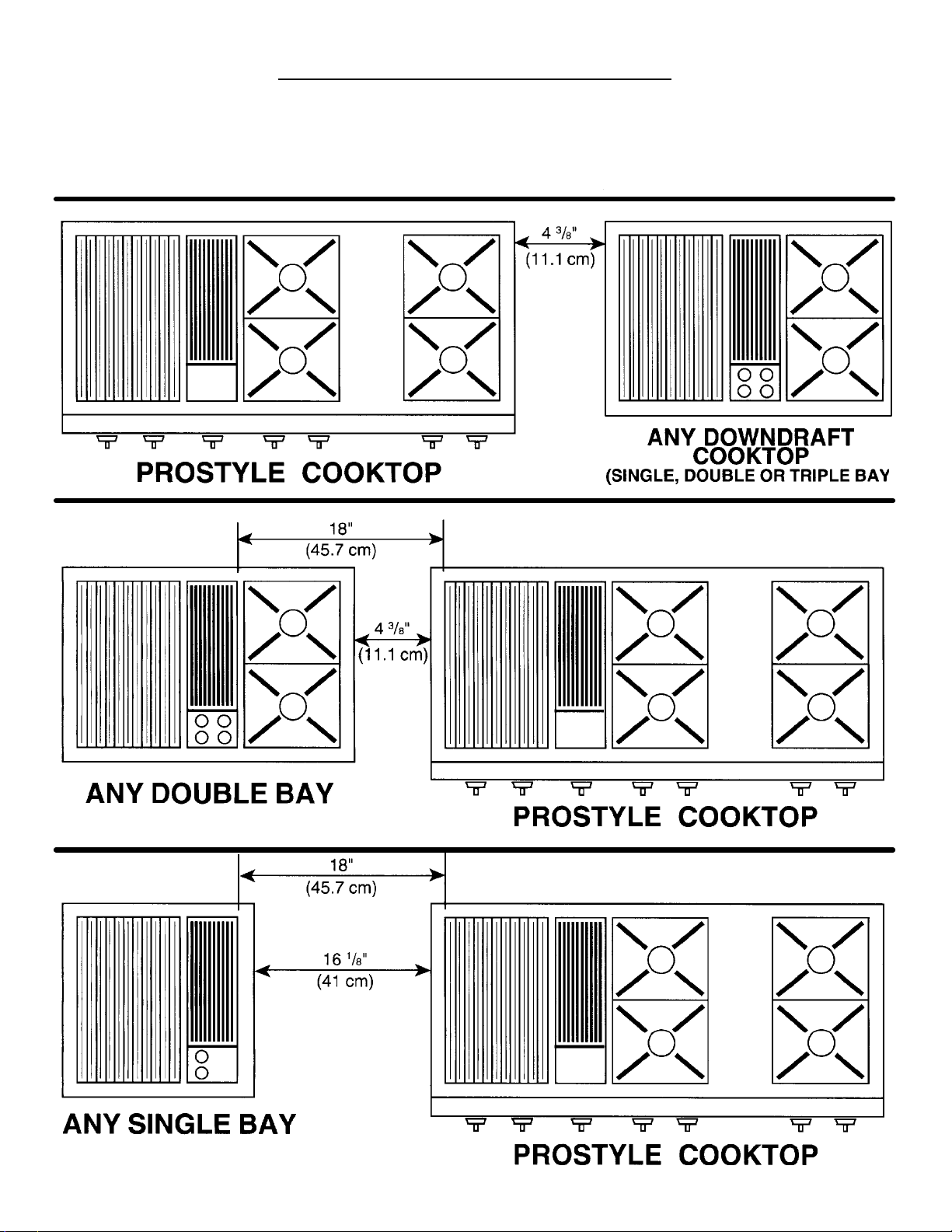
MINIMUM SPACING REQUIREMENT
GAS GRILL COOKTOPS
Forinstallinga TripleBayDowndraftCooktopincombinationwithanother DowndraftCooktop,theminimum spacing between adjacent units must be provided, as shown, for satisfactory performance.
10

REQUIRED ADJUSTMENTS AT TIME OF INSTALLATION
The installation of this appliance must conform with local codes, or in the absence of local codes, with
thelatesteditionoftheNationalFuelGasCodeANSIZ223.1USAorcurrentCAN/CGA-B149Installation
Code.
ThisrangewasmanufacturedforusewithNaturalGas. IfLPgasisthe fuelofchoice,followtheconversion
to LP procedure found in the installation instructions.
Test all external connections for gas leaks. Never test for gas leaks with an open flame.
Test all electrical connections.
Adjust all air shutters for proper flame.
Adjust all valves for low flame settings.
Test the ventilation system for proper installation.
If a problem exists with the downdraft system, check the ducting installation to make sure it conforms to
the Jenn-Air specifications. Most downdraft system problems are attributed to poor ducting practices.
Contact your installer if the ventilation system will not remove smoke or cooking fumes from well trimmed
cuts of meat.
If ventilation problems persist contact your authorized Jenn-Air Service Contractor.
11

403 WEST FOURTH STREET, NORTH · NEWTON, IA 50208

INSTRUCCIONES
DE
INSTALACIÓN
Las dimensiones se muestran en pulgadas y centímetros
AVISO AL INSTALADOR: Deje estas instrucciones con el electrodoméstico.
AVISO AL CONSUMIDOR: Conserve estas instrucciones como referencia futura.
Superficie convencional para
cocinar de gas con parrilla
Prostyletttt de módulo triple
Modelo JGD8348BDP
403 WEST FOURTH STREET, NORTH D NEWTON, IA 50208
* El ventilador puede
girarse para orientarlo
horizontalo verticalmente aflojando las
tuercas de la entrada del
ventilador.
Asequible desde adentro
de la cámara de
ventilación.
VEALAPÁGINA2
PARA
ESPACIO LIBRE
MÍNIMO
REQUERIDO
PARTE INFERIOR
DE LA TABLA
VENTILADOR
SELECCIONE EL CORTE
APROPIADO PARA EL DUCTO
(VEA LAS INSTRUCCIONES DE
INSTALACIÓN DEL DUCTO).
REGULADOR DE
PRESIÓNDEL
ELECTRODOMÉSTICO
REGULADOR
DE PRESIÓN
DEL ELECTRODOMÉSTICO
CAJA DE
CUBIERTA DE
RECIPIENTE
DE DRENAJE
CABLES
ENCONTRAR LAS
DIMENSIONES
DEL HUECO
CADA
EXTREMO
EXTREMO
DE LA CAJA
DEL
QUEMADOR
PARTE
INFERIOR
DE LA CAJA
DEL
QUEMADOR
INSTRUCCIONES PARA EL INSTALADOR:
S La dimensión “A” - proporciona 2² mínimas (5.08 cm) de espacio libre del gabinete al
motor para fines de enfriamiento.
S NOTA: En donde sea posible, se recomiendan 6² (15.54 cm) para darle servicio al motor
y al ventilador.
S Espacio libre lateral: Las parrillas instaladas muy cerca de una pared deben tener un
espacio libre de 8² (20.32 cm) como mínimo.
S Debe proporcionarse acceso para quitar y vaciar el recipiente de grasa.

LÍNEAS DE CORTE
(SOLAMENTEDEL
FRENTE)
RECORTES DEL GABINETE y DEL MOSTRADOR
HUECO
EXISTENTE
(VISTA DE FRENTE)
HUECO
EXISTENTE
GABINETE
Según se requiera para la instalación
*Se recomiendan 8² (20.32 cm)
para los gabinetes a la medida.
NOTA: SE REQUIERE UN
PANEL INFERIOR DE CONTROL
SI ESTA DIMENSIÓN EXCEDE
53/4²²²² (14.60 cm).
VEA LA PÁGINA 3 EN RELACIÓN
AL REFUERZO DE LA PARTE
DELANTERA DEL GABINETE
Vea las sugerencias de recorte 1-4 en la página 6.
NOTA: Las tolerancias de las dimensiones del
hueco son de 1/16 pulg (0.16 cm)
ÁREA
VISTA DESDE
ARRIBA
DE RECORTE
PROFUNDIDAD DEL MOSTRADOR
DEL MOSTRADOR
46 13/16²
(118.90 cm)
QUITE LOS APOYOS DE L AS ESQUINAS
SEGÚN SEA NECESARIO
TÍP. (4) HOJAS
MOSTRADOR
2

Instalación de gabinetes encima de la
parrilla Jenn-Air
El espacio libre horizontal mínimo entre el borde del
electrodoméstico y la construcción combustible que se
extienda de la superficie para cocinar a 18² (45.7 cm) por
encima de la superficie para cocinar es:
1:² (4.45 cm) en la parte posterior
8² (20.32 cm) a los lados
NOTA: Éste no es el espacio libre que se recomienda
sino el espacio libre mínimo permitido.
18²
(45.7 cm)
Las líneas punteadas
indican la construcción de
la campana de la estufa.
* Para eliminar el riesgo de quemaduras o incendios al
atravesarse por encima de las unidades calientes de la
superficie, debe evitarse el uso del espacio de
almacenamiento de los gabinetes localizados encima
de las unidades de la superficie. Si los gabinetes se
van a usar para almacenamiento, el riesgo puede
reducirse usando una campana de estufa que
sobresalga horizontalmente cuando menos 5 pulgadas
(12.7 cm) de la parte inferior de los gabinetes.
8²
(20.3 cm)
ESPACIO LIBRE MÍNIMO
*A = 30² (76.2 cm) espacio libre mínimo vertical entre
la superficie para cocinar y la construcción
encima del electrodoméstico.
B= 13² (33.02 cm) profundidad máxima de los
gabinetes instalados por encima de la superficie
para cocinar.
Trate de no usar los gabinetes que están encima de la
superficie para cocinar como espacios para almacenar ya
que así eliminará los riesgos potenciales de tener que
atravesarse cuando haya llamas encendidas.
Gabinetes encima de la superficie para
cocinar
La profundidad máxima de los gabinetes instalados por
encima de la superficie para cocinar es de 13 pulgadas
(33 cm).
PRECAUCIÓN: ALGUNOS GABINETES Y
MATERIALES DE CONSTRUCCIÓN NO ESTÁN
DISEÑADOS PARA RESISTIR EL CALOR
PRODUCIDO DURANTE LA OPERACIÓN NORMAL
DEL ELECTRODOMÉSTICO INDICADO, POR LO
TANTO PODRÍA OCURRIR DECOLORACIÓN O
DAÑOS, TALES COMO DESLAMINACIÓN.
3

Instalación del electrodoméstico
Siga cuidadosamente las instrucciones adjuntas acerca
de los ductos.
Este electrodoméstico está diseñado para ventilarse
siempre hacia el exterior.
NOTA: En algunos estilos de gabinetes, podría ser
necesario tener que reforzar la parte delantera del
gabinete sujetando una abrazadera del frente a la parte
posterior del gabinete por dentro desde debajo de la caja
del quemador.
El recorte del mostrador, el recorte del frente del gabinete
y los huecos de los ductos deberán prepararse de
acuerdo con las ilustraciones de las páginas 1 y 2.
Instale el panel de control inferior en el fondo del recorte
del gabinete según se muestra, usando los tornillos del
paquete de herrajes. (Figura 1).
Vista desde arriba
PANEL INFERIOR DE CONTROL
Figura 1
Coloque la unidad en el recorte del mostrador. El panel
principal de control debe sobreponerse a la parte superior
del panel inferior de control según se muestra. (Figura 2).
Instale los ductos de acuerdo con las instrucciones
provistas. Los huecos de los ductos en el gabinete se
muestran en el dibujo de la página 1. Haga las
conexiones eléctricas y de gas según se describe más
adelante en esta sección de instrucciones.
La instalación de este electrodoméstico debe estar en
conformidad con los códigos locales, o si éstos no
existieran, con la última edición del Código Nacional de
Gas Combustible, ANSI Z.223.1 EE.UU. o el CÓDIGO
DE INSTALACIÓN actual CAN/CGA-B149.
El suministro eléctrico requerido es de 110/120-voltios,
C.A., 15 amp, 60 Hz. Este electrodoméstico está
equipado con un tipo de cordón eléctrico conectado a
tierra. Debe proveerse un tomacorriente conectado a
tierra. Se recomienda, por comodidad, que este
tomacorriente se ubique en el área que se muestra en la
ilustración sombreada. Cuando se instale este
electrodoméstico, debe conectarse a tierra de acuerdo
con los códigos locales, o si éstos no existieran, con la
última edición del Código Nacional Eléctrico ANSI/NFPA
No. 70 EE.UU. o al Código Canadiense Eléctrico CSA
STANDARD C22.1 parte 1.
PANEL INFERIOR DE
CONTROL
Figura 2
10 1/16²
(25.56 cm)
46 13/16² (118.90 cm)
Para darle servicio a la superficie para
cocinar
Cuando se le de servicio a la superficie para cocinar es
necesario quitar la parte superior principal, antes de
quitar el panel de control.
4

Conexión del electrodoméstico al
suministro de gas
LA CONEXIÓN AL SUMINISTRO DE GAS DEBE
REALIZARLA UN TÉCNICO CAPACITADO DE
SERVICIO O UN INSTALADOR DE ELECTRODOMÉSTICOS DE GAS. Las pruebas de fugas de gas
del electrodoméstico las debe realizar el instalador de
acuerdo con las instrucciones proporcionadas.
Instale una válvula de cierre manual en un lugar accesible
en la tubería de gas de la parte exterior de este
electrodoméstico para fines de abrir y cerrar el gas que
va al electrodoméstico.
Haga la conexión de gas a la entrada del regulador de
presión del electrodoméstico con una rosca de tubería
machode1/2². Use en las conexiones de la tubería un
compuesto para uniones de tubería aprobado que sea
resistente a la acción del gas butano. Pruebe todas las
uniones para asegurarse de que no haya fugas con una
solución de agua y jabón u otro medio aprobado de
detección de fugas. Nunca pruebe las fugas con las
llamas encendidas.
PRECAUCIÓN: LA GARANTÍAQUEDA ANULADAEN
EL EQUIPO JENN-AIR CUANDO SE INSTALE PARA
OTRO FIN QUE NO SEA EL RECOMENDADO POR
EL FABRICANTE. DEBEN UTILIZARSE LAS TAPAS
DE PARED Y LAS TRANSICIONES RECOMENDADAS PARA OBTENER UNA OPERACIÓN E
INSTALACIÓN CORRECTAS.
Obturadores de aire de cartucho del
quemador de la parrilla y del quemador
de la superficie para cocinar
(Vea las ilustraciones “A” y “B”)
El obturador de aire del lado izquierdo controla la mitad
posterior de los quemadores. El obturador de aire del lado
derechocontrolala mitaddelantera. Los obturadores deaire
del cartucho del quemador de la superficie se acceden a
través de las aberturas en la parte inferior de la caja del
cartucho.
Deslice los obturadores deaire hacia atrás o hacia adelante
para aumentar o reducir el tamaño de la abertura del aire.
Losobturadoresquedan muy bienajustados,así que podría
ser necesario tener que usar la hoja de un destornillador o
unas pinzas con punta de aguja para hacer este ajuste (vea
la ilustración).
Observe los cambios en la apariencia de la llama conforme
mueve el obturador de aire. El ajuste es aceptable cuando
aparece una llama claramente definida, azul y uniforme en
el ajuste más alto de la llama. El buen ajuste del obturador
de aire garantizaque permanezca correctamente colocado.
Obturador de aire del quemador de la parrilla y
quemador de la superficie para cocinar
(si así está equipado)
(PARA
ABRIR)
ADVERTENCIA
INSTRUCCIONES ELÉCTRICAS DE
CONEXIÓN A TIERRA
ESTE ELECTRODOMÉSTICO ESTÁ EQUIPADO
CON UNA CLAVIJA DE TRES PUNTAS DE
CONEXIÓN A TIERRA PARA PROTEGERLO
CONTRA RIESGOS DE DESCARGAS Y DEBE
CONECTARSE DIRECTAMENTE EN UN
RECEPTÁCULO CORRECTAMENTE CONECTADO
A TIERRA. NO CORTE NI QUITE LA PUNTA DE
TIERRA DE ESTA CLAVIJA.
Ajuste del obturador de aire
Este electrodoméstico se embarca de fábrica con los
obturadores de aire ajustados para usarse con gas
natural. Si es necesario ajustarlos más o reajustarlos para
usarse con gas butano, ajuste los obturadores de aire del
modo siguiente:
ABERTURA
DEL AIRE
OBTURADOR
DE AIRE
INSERTE LA HOJA DE UN DESTORNILLADOR EN LA RANURA Y
GIRE EJERCIENDO UNA PRESIÓN
LEVE PARA PERMITIR QUE EL
OBTURADOR DE AIRE SE
DESLICE CON FACILIDAD
(PARA
CERRAR)
Ilustración “A”
Encualquierquemador, el cerrardemasiadoelobturadorde
aire haráque la llama se vuelva suave y con puntaamarilla.
Abrir demasiado el obturador de aire hará que la llama se
separe de los puertos del quemador. El ajuste correcto
producirá una llama claramente definida, azul y uniforme.
OBTURADOR
DE AIRE
Ilustración “B”
5

Sugerencias importantes de
instalación
1. Achaflane todos los bordes expuestos del laminado
decorativo para evitar daños por desportilladuras.
2. Haga radiales en las esquinas de los recortes y líjelas
para asegurarse que los bordes queden lisos y evitar
que se quiebren las esquinas.
3. Los bordes disparejos, las esquinas interiores que no
se han redondeado y los ajustes forzados pueden
contribuir a que se quiebre el laminado del mostrador.
4. El mostrador debe estar apoyado a 3² (7.6 cm) del
recorte.
En cualquier quemador, cerrar demasiado el
obturador de aire hará que la llama se vuelva suave y
de punta amarilla. Abrir demasiado el obturador de
aire hará que la llama se separe de los puertos del
quemador. El ajuste correcto producirá una llama
claramente definida, azul y uniforme.
Ajuste de llama baja
(Vea la ilustración “C”)
Este electrodoméstico se embarca de fábrica con ajustes
de llama bajo y medio para usarse con gas natural. Si son
necesarios ajustes adicionales, o para reajustarlo para
usarse con gas butano, continúe del modo siguiente:
1. Encienda el quemador y coloque la perilla de control en
la llama baja.
2. Quite la perilla de control del vástago de la válvula.
EN EL SENTIDO DE LAS
MANECILLASDEL RELOJ
PARA REDUCIR EL
TAMAÑO DE LA LLAMA
Ilustración “C”
EN SENTIDO CONTRARIO AL
DE LAS MANECILLAS DEL
RELOJ PARA AUMENTAR EL
TAMAÑO DE LA LLAMA
Prueba de presión
La presión máxima de suministro de gas para el regulador
de presión del electrodoméstico proporcionado con este
electrodoméstico es de 14² W.C. La presión de prueba
para revisar el regulador de presión del electrodoméstico
debe ser cuando menos de 6² W.C. para gas natural, y
cuando menos de 11² W.C. para gas butano. Se embarca
de fábrica ajustado para usarse con gas natural a 5² W.C.
Este electrodoméstico y su válvula de cierre individual
deben estar desconectados del sistema de tubería de
suministro de gas durante las pruebas de presión a
presiones de prueba por encima de 1/2² PSIG (3.5 k Pa).
Este electrodoméstico debe estar aislado del sistema de
tubería del suministro de gas cerrando la válvula de cierre
individual durante las pruebas de presión del sistema de
tubería de suministro de gas a presiones de prueba
iguales o menores de 1/2² PSIG (3.5 k Pa).
PRECAUCIÓN: NUNCA USE UNA HOJA METÁLICA
PARA SACAR LA PERILLA. SI ÉSTA NO PUEDE
SACARSE CON FACILIDAD, INTRODUZCA UN
SECADOR DOBLADO DE TELA POR DEBAJO DELA
PERILLA Y TIRE DEL SECADOR HACIA ARRIBA
EJERCIENDO UNA PRESIÓN UNIFORME.
3. Inserte un destornillador de hoja delgada y plana dentro
del receso al centro del vástago de la válvula y
enganche la hoja en la ranura en el tornillo de ajuste.
4. Gire el tornillo de ajuste del centro del vástago para
ajustar el tamaño de la llama.
...enelsentidodelasmanecillas del reloj para
reducirla.
...ensentidocontrarioaldelasmanecillas del reloj
para aumentarla.
5. Coloque de nuevo la perilla de control cuando termine
el ajuste.
Un ajuste apropiado producirá una llama estable, uniforme
en color azul de tamaño mínimo. El ajuste final debe
revisarse girando la perilla de alto a bajo varias veces sin
apagar la llama.
Este ajuste, en el ajuste bajo, proporcionará
automáticamente el tamaño correcto de llama para el
ajuste medio.
Conversión del regulador de presión
del electrodoméstico
(Vea la ilustración “D”)
Esta unidad se suministra con un regulador de presión para
electrodomésticos Maxitrol. Siga las instrucciones de la
ilustración “D”.
REGULADOR DE PRESIÓN PARA
ELECTRODOMÉSTICOS MAXITROL
APLIQUE PRESIÓN HACIA ABAJO CON
EL DEDO EN LOS BORDES DEL DISCO
PARA VOLVER A COLOCAR EL
PASADOR EN LA TAPA
APLIQUE
PRESIÓN
LATERAL CON
EL DEDO PARA
NAT LP
QUITAR EL
PASADOR DE
LA TAPA
NAT
CONVERTIDOR
TAPA Y
PASADOR
LP
Ilustración “D”
6

Conversión a gas butano
Este electrodoméstico se embarca de fábrica equipado
para usarse con gas natural. Para convertirlo de gas
natural a gas butano, realice los pasos 1 al 4.
1. Quite las campanas de orificio de gas natural. Instale
las campanas adjuntas de orificio codificadas por color.
Se encuentran en un paquete que está sujeto en el
área impelente externa de este electrodoméstico.
(Vea la ilustración “E”, más adelante, y las
instrucciones de conversión a gas butano de la
página 8).
2. Invierta la tapa en el regulador de presión convertible
(si está equipado) localizado en la entrada del múltiple
de gas.
3. Ajuste los obturadores de aire en los quemadores
individuales para obtener la apariencia correcta de la
llama.
4. Coloque el ajuste bajo de llama en cada quemador
girando el tornillo de ajuste en el centro del vástago de
la válvula.
Para realizar estos ajustes de conversión siga las
instrucciones y las ilustraciones (“A” a la “E”, en las
páginas 5-7).
IMPORTANTE
Aplique un líquido anticorrosivo detector de fugas en
todas las uniones y accesorios de la conexión de gas
entre la válvula de cierre de la tubería de suministro y
la estufa. Incluya los accesorios de gas y las uniones
de la estufa si las conexiones se alteraron durante la
instalación. Revise si hay fugas. Las burbujas que
aparezcan alrededor de los accesorios y las
conexiones indicarán que hay fugas. Si aparece una
fuga, cierre la válvula de la tubería de suministro de
gas, apriete las conexiones, abra la válvula de cierre
de la tubería de suministro de gas, y vuelva a revisar
si hay fugas. Nunca realice pruebas de fugas con la
llama encendida.
Este electrodoméstico se embarca de fábrica con
campanas de orificio para usarse con gas natural. Para
convertirlo de gas natural a gas butano, coloque una llave
española de 1/2² a la sección hexagonal de la campana
de orificio. Gire en sentido contrario al de las manecillas
del reloj para quitarla. Conserve las campanas de orificio
de gas natural que quitó del electrodoméstico para usarlas
en el futuro. Instale las campanas suministradas de
orificio codificadas por color. (Vea las instrucciones de
conversión a gas butano anteriores y en la página 8). Gire
en el sentido de las manecillas del reloj para instalarla.
Mantenga la dimensión especificada en la ilustración “E”.
LLAVE
ESPAÑOLA DE
1/2²
GIRE EN SENTIDO
CONTRARIO AL DE LAS
MANECILLASDEL RELOJ
PARA QUITARLA
11/16²²²²
CAMPANA DE ORIFICIO
GIRE EN EL
SENTIDO DE LAS
MANECILLASDEL
RELOJ
PARA APRETARLA
Ilustración “E”
Ajustes de control
El tamaño y tipo de recipientes de cocina y la cantidad y
tipo de alimentos que se cocinen influirán en el ajuste que
se necesita para obtener los mejores resultados de
cocción. El ajuste indicado deberá servir como una guía
mientras se familiariza con la superficie para cocinar.
Use el ajuste de llama HI (alto)
para hacer que los alimentos
hiervan rápidamente o para
comenzar una operación de
cocción. Luego reduzca el ajuste
para continuar el cocimiento.
Nunca desatienda los alimentos
cuando estén en el ajuste de
llama HI (alto).
El ajuste Med (medio) se usa
para continuar una operación de
cocción. Los alimentos no se
cocinarán más rápido cuando se
usaelajustedellamaHI (alto)
que con el que se necesita para
mantener un hervor suave.
Recuerde, el agua hierve a la
misma temperatura aunque
hierva suave o vigorosamente.
Use el ajuste LO (bajo) para
mantener los alimentos a
temperatura de servir sin que se
sigan cocinando. Se dará cuenta
que podría haber un poco de
cocción adicional si el recipiente
se encuentra tapado.
7

PARA CONVERTIR EL ELECTRODOMÉSTICO PARA USARSE CON GAS BUTANO
Instrucciones de conversión de gas natural a gas butano (LP)
ADVERTENCIA
La conversión a gas butano debe realizarla un
contratista autorizado de servicio de Jenn-Air
(u otra agencia calificada) de acuerdo con las
instruccionesdel fabricante y todos los códigos
y requisitos de la autoridad que tenga
jurisdicción. El no seguir las instrucciones
podría causar lesiones graves o daños
materiales.La agencia calificadaque realice el
trabajo asume la responsabilidad de esta
conversión.
CP
ADVERTENCIA
LA ENERGÍA ELÉCTRICA DEBE ESTAR
APAGADA Y EL GAS CERRADO ANTES DE
REALIZAR LA CONVERSIÓN
Modelos - JGD8348BDP
Múltiple — presión necesaria del gas butano - 10² W.C.
Presión necesaria de entrada del gas butano al regulador
de presión del electrodoméstico - 11² -12² W.C.
Las campanas de orificio de conversión se adjuntan con
este modelo.
Entrada de gas butano especificada - 46,000 BTU/hora.
DP
DD
IP
JGD8348BDP
ID
QUEMADOR BTU/hora ORIFICIO PULGADAS COLOR
Izquiero posterior (IP) 7500 #66 .033 Zinc
Izquierdo delantero (ID) 7500 #66 .033 Zinc
Centro posterior (CP) 6500 #68 .031 Rojo
Centro delantero (CD) 9000 #63 .037 Azul
CD
DIÁMETRO
Derecho posterior (DP) 6500 #68 .031 Rojo
Derecho delantero (DD) 9000 #63 .037 Azul
8

PARA CONVERTIR EL ELECTRODOMÉSTICO P ARA USARSE CON GAS NATURAL
Instrucciones de conversión de gas butano
(LP) a gas natural
Si este electrodoméstico se ha convertido para uso con
gas LP, deben realizarse cada una de las siguientes
modificaciones paraconvertirla unidad nuevamente a gas
natural.
ADVERTENCIA
La conversión a gas natural debe realizarla un
contratista autorizado de servicio de Jenn-Air
(u otra agencia calificada) de acuerdo con las
instruccionesdel fabricante y todos los códigos
y requisitos de la autoridad que tenga
jurisdicción. El no seguir las instrucciones
podría causar lesiones graves o daños
materiales. La agencia calificada que realice
este trabajo asume toda la r e sponsabilidad de
dicha conversión.
ADVERTENCIA
LA ENERGÍA ELÉCTRICA DEBE ESTAR
APAGADA Y EL GAS CERRADO ANTES DE
REALIZAR LA CONVERSIÓN
DP
Modelo - JGD8348BDP
Múltiple — presión de gas natural necesaria - 5² W.C.
Presión necesaria de entrada de gas natural al regulador
de presión del electrodoméstico - 6² -7² W.C.
Gas natural especificado de entrada - 56,000 BTU/hora.
A. Coloquede nuevolas campanasde orificio. Realice los
pasos 1 al 4 dela página7. Localice seis (6) campanas
de orificio para gas natural (con los números pequeños
estampados por un lado que conservó de la unidad
original de gas natural). Página 5, ilustración “E”. Las
dos campanas marcadas con el número .0520 (orificio
#55) son para los quemadores izquierdo delantero e
izquierdo posterior. Las cuatro campanas marcadas
con el número .0595 (orificio #53) son para los dos
quemadores derechos.
Para realizar estos ajustes de conversión siga las
instrucciones e ilustraciones (“A” a la “E”) páginas
5-7.
B. Invierta la tapa del regulador de presión del
electrodoméstico(vealailustración “D”,página6). Con
el electrodoméstico instalado, el regulador de presión
está ubicado en el lado inferior derecho del
electrodoméstico en la entrada del múltiple de gas.
Identifique el tipo del regulador de presión de la unidad
y siga las instrucciones en la ilustración apropiada.
C. Ajuste la llama en bajo en cada quemador. Siga las
instrucciones para el ajuste de llama bajo de
quemadores en la página 7 para aumentar el tamaño
de la llama para hervir a fuego lento.
CP
IP
JGD8348BDP
ID
QUEMADOR BTU/hora ORIFICIO PULGADAS COLOR
Izquierdo posterior (IP) 8,000 #55 .0520 Verde
Izquierdo delantero (ID) 8,000 #55 .0520 Verde
Centro posterior (CP) 10,000 #53 .0595 Cobre
Centro delantero (CD) 10,000 #53 .0595 Cobre
Derecho posterior (DP) 10,000 #53 .0595 Cobre
Derecho delantero (DD) 10,000 #53 .0595 Cobre
CD
DIÁMETRO
DD
9

REQUISITOS MÍNIMOS DE ESPACIAMIENTO
SUPERFICIES PARA COCINAR CON PARRILLA DE GAS
Para instalar la Superficie para cocinar de módulo triple con tiro invertido en combinación con otra
superficie para cocinar con tiro invertido, debe mantenerse el espaciamiento mínimo entre las
unidades adyacentes, según se muestra, para obtener un desempeño satisfactorio.
CUALQUIER SUPERFICIE PARA
COCINAR DE TIRO INVERTIDO
SUPERFICIE PARA COCINAR PROSTYLE
(MÓDULO SENCILLO, DOBLE O TRIPLE)
CUALQUIERA DE
MÓDULO DOBLE
CUALQUIERA DE
MÓDULO SENCILLO
SUPERFICIE PARA COCINAR PROSTYLE
SUPERFICIE PARA COCINAR PROSTYLE
10

AJUSTES QUE SE REQUIEREN A LA HORA DE LA INSTALACIÓN
La instalación de este electrodoméstico debe estar en conformidad con los códigos locales, o si éstos
no existieran, con la última edición del Código Nacional de Gas Combustible ANSI Z223.1 EE.UU. o el
Código de Instalación CAN/CGA-B149 actual.
Esta estufa fue fabricada para usarse con gas natural. Si se elige usar gas LP, siga el procedimiento de
conversión a LP en las instrucciones de instalación.
Pruebe todas las conexiones externas para verificar que no haya fugas de gas. Nunca realice pruebas
de fugas de gas con una llama encendida.
Pruebe todas las conexiones eléctricas.
Ajuste los obturadores de aire para obtener una llama adecuada.
Ajuste todas las válvulas en los ajustes de llama baja.
Pruebe el sistema de ventilación para verificar la instalación correcta.
Siexiste un problemacon el sistemade tiro invertido,revisela instalaciónde losductos para asegurarse
que esté en conformidad con las especificaciones de Jenn-Air. La mayoría de los problemas con el
sistema de tiro invertido son debido a los procedimientos incorrectos de la instalación de los ductos.
Comuníquese con el instalador si el sistema de ventilación no absorbe el humo o los gases de cocción
de los cortes de carne magra.
Si persisten los problemas de ventilación, comuníquese con el contratista autorizado de servicio de
Jenn-Air.
11

403 WEST FOURTH STREET, NORTH · NEWTON, IA 50208

MISE EN
SERVICE
Dimensions montrées en pouce et en centimètres
À L’INTENTION DE L’INSTALLATEUR : Veuillez laisser ces instructions avec l’appareil.
À L’INTENTION DU CONSOMMATEUR : Veuillez conserver ces instructions pour référence ultérieure.
Prostyletttt àtriplebaie
Modèle JGD8348BDP
403 WEST FOURTH STREET, NORTH D NEWTON, IA 50208,
ÉTA TS--UNIS
Plaque de cuisson à grilloir
*Le ventilateur peut être
orienté à l’horizontale ou
àlaverticaleen
desserrant les écrous qui
se trouvent autour de
l’admission du ventilateur.
Accessible à l’intérieur de
la chambre de ventilation.
VOIR PAGE 2
POUR LES
DIMENSIONS DE
LA DÉCOUPE
À CHAQUE
EXTRÉMITÉ
DU FOND
DE LA
BOÎTE DES
BRÛLEURS
EXTRÉMITÉ
DE LA
BOÎTE DES
BRÛLEURS
DÉGAGE-
MENT
MIN. DE
15 13/15²
(40.2 CM)
REQUIS
FOND DE L’ARRÊT
DE GRAISSE
VENTILATEUR
SÉLECTIONNEZ LA DÉCOUPE
POUR CONDUIT QUI CONVIENT
(VOIR LES INSTRUCTIONS DE
POSE DE CONDUITS.)
DÉTENDEUR DE
L’APPAREIL
DÉTENDEUR
DE
L’APPAREIL
BOÎTIER
GODET
D’ÉCOULE-MENT
COUVRE-FILS
INSTRUCTIONS À L’INTENTION DE L’INSTALLATEUR :
S La dimension A prévoit un dégagement minimum de 2 po (5,08 cm) par rapport au moteur à
des fins de refroidissement.
S REMARQUE : Si les conditions le permettent, un dégagement de 6 po (15,54 cm) est
recommandé afin de permettre l’accès au moteur/ventilateur à des fins de service après-vente.
S Dégagement latéral : Les grilloirs qui se trouvent à côté d’une paroi latérale doivent avoir un
dégagement minimum de 8 po (20,32 cm).
S Il doit pouvoir y avoir accès au récipient à graisse pour le vider.

LIGNES DE
DÉCOUPE(DEVANT
SEULEMENT)
DÉCOUPES DANS L’ARMOIRE ET LE COMPTOIR
OUVERTURE
EXISTANTE
(VUE DE L’AVANT)
Tel que requis pour la mise en service
ARMOIRE
OUVERTURE
EXISTANTE
*8 po (20,32 cm)
recommandés pour les
armoirespersonnalisées.
REMARQUE : UN PANNEAU DE
COMMANDE PLUS BAS EST
EXIGÉ SI CETTE DIMENSION
EST SUPÉRIEURE À 5 3/4 PO
(14,60 CM).
VOIR LA PAGE 3 POUR LE
RENFORCEMENT DE L’AVANT
DE L’ARMOIRE
Voirlessuggestions1à4concernantladécoupe page 6.
REMARQUE : Tolérance prévue de + 1/16 po
(0,16 mm) dans les dimensions de la découpe
SURFACE DE LA
VUE
DU DESSUS
DÉCOUPE DU
PROFONDEUR DU COMPTOIR
COMPTOIR
46 13/16²
(118,90 cm)
ENLEVER LES CORNIÈRES DE
SUPPORT S’IL Y A LIEU NORMALEMENT
4 ÉPAISSEURS
COMPTOIR
2

Pose d’armoires au-dessus de votre
grilloir Jenn-Air
Le dégagement horizontal minimum entre le bord de
l’appareil et des structures combustibles dépassant de la
surface de cuisson jusqu’à une hauteur de 18 po
(45,7 cm) au-dessus de la surface de cuisson est le
suivant :
1 3/4 po (4,45 cm) à l’arrière
8 po (20,32 cm) sur les côtés
REMARQUE : Ceci n’est pas le dégagement
recommandé mais le dégagement minimum possible.
Éviter l’utilisation d’armoires de rangement au-dessus dela
surface de cuisson pour éliminer les risques potentiels qui
y sont liés, tels que se pencher au-dessus de flammes pour
prendre un article dans l’armoire.
Les pointillés indiquent
l’emplacement de la hotte.
18 po
(45,7
cm).
8po
(20,3 cm).
DÉGAGEMENT
MIN.
*A = 30 po (76,2 cm) de dégagement vertical minimum
entre la surface de cuisson et les structures qui
se trouvent au-dessus de l’appareil.
B = 13 po (33,0 cm) de profondeur maximum pour les
armoires qui se trouvent au-dessus de la surface
de cuisson.
*Pour éliminer les risques de brûlure ou d’incendie en se
penchant au-dessus de surfaces brûlantes, il est
fortement conseillé d’éviter de placer des espaces de
rangement au-dessus de brûleurs ou d’éléments
chauffants de la surface de cuisson. S’il doit y avoir des
armoires au-dessus de la surface de cuisson, les
risques peuvent être réduits en posant une hotte qui
dépasse d’un minimum de 5 po (12,7 cm) du bas
des armoires.
Armoires au-dessus de la surface de
cuisson
La profondeur maximum des armoires posées au-dessus
de la surface de cuisson est de 13 po (33 cm).
PRUDENCE : CERTAINES ARMOIRES ET
CERTAINS MATÉRIAUX DE CONSTRUCTION NE
SONT PAS CONÇUS POUR SUPPORTER LA
CHALEUR PRODUITE LORS DU
FONCTIONNEMENT NORMAL D’UN APPAREIL.
UNE DÉCOLORATION OU DES DÉGÂTS TELS QUE
LA DÉLAMINATION PEUVENT SE PRODUIRE.
3

Mise en service de l’appareil
Suivre les instructions concernant les conduits fournies
avec ceux-ci avec soin.
Cet appareil est conçu pour que l’air aspiré soit toujours
rejeté à l’extérieur.
La découpe dans le comptoir, la découpe dans le devant
de l’armoire et la découpe pour le conduit doivent être
préparées conformément à l’illustration des pages 1 et 2.
Poser le panneau de commande inférieur dans la
découpe inférieure de l’armoire tel qu’indiqué, en utilisant
les vis fournies dans le paquet de visserie. (Voir la figure
1).
Vue du dessus
Figure 1
Placer l’appareil dans la découpe dans le comptoir. Le
panneau de commande principal doit chevaucher le
dessus du panneau de commande inférieur tel qu’indiqué.
(Voir la figure 2).
PANNEAU DE COMMANDE INFÉRIEURTROL
REMARQUE : Certains styles d’armoires pourront exiger
le renforcement de l’avant de l’armoire en fixant un renfort
de l’avant vers l’arrière à l’intérieur de l’armoire, sous la
boîte des brûleurs.
Poser le conduit conformément aux instructions fournies.
Les ouvertures prévues pour le conduit dans l’armoire
sont montrées sur l’illustration de la page 1. Effectuer les
raccordements à l’électricité et au gaz tel qu’indiqué
ci-dessous.
La mise en service de cet appareil doit être conforme aux
codes locaux ou, en l’absence de tels codes, avec la
norme ANSI Z.223.1, dernière édition, du National Fuel
Gas Code ou du CODE DES INSTALLATIONS B149
CAN/ACG en vigueur.
L’alimentation électrique fournie doit être de 110/220 V
alternatifs, 15 A et 60 Hz. Cet appareil est équipé d’un
cordon d’alimentation avec raccordement à la terre. Il doit
être branché dans une prise de courant reliée à la terre. Il
est recommandé que, pour plus de facilité, la prise soit
dans la zone indiquée par une région grisée sur
l’illustration. Une fois en place, l’appareil doit être relié à la
terre conformément aux codes locaux ou, en l’absence de
codes locaux, aux normes ANSI/NFPA n 70 de l’édition la
plus récente du National Electrical Code ou aux normes
CSA C22.1 du Code canadien de l’électricité, partie 1,
en vigueur.
PANNEAU DE COMMANDE
INFÉRIEURTROL
Figure 2
10 1/16 po
(25,6 cm)
46 13/16 po (118.9 cm)
Dépannage de la plaque de cuisson
Si la plaque de cuisson exige des réparations, il faudra
enlever le dessus principal avant d’enlever le panneau de
commande.
4

Raccordement de l’appareil au gaz
LE RACCORDEMENT AU GAZ DOIT ÊTRE EFFECTUÉ
PAR UN TECHNICIEN AYANT REÇU LA FORMATION
APPROPRIÉE OU PAR UN INSTALLATEUR
D’APPAREILS À GAZ. La vérification de l’absence de
fuites sera effectuée par l’installateur conformément aux
directives fournies.
Poser un robinet de gaz dans un endroit accessible de la
conduite de gaz extérieure à l’appareil afin de pouvoir
couper ou ouvrir l’alimentation en gaz de l’appareil.
Effectuer le raccordement à l’arrivée de gaz du détendeur
de cet appareil avec une conduite mâle filetée de 1/2 po
(13 mm). Utiliser une pâte à filetage résistant à l’action du
gaz GPL sur les raccords. Vérifier la présence éventuelle
de fuites au niveau de tous les joints à l’aide d’eau
savonneuse ou de tout autre moyen reconnu de détection
de fuites. Ne jamais vérifier la possibilité de fuites à l’aide
d’une flamme.
PRUDENCE : LA GARANTIE EST ANNULÉE POUR
TOUT MATÉRIEL JENN-AIR INSTALLÉ
AUTREMENT QUE TEL QUE RECOMMANDÉ PAR
LE FABRICANT. LES CAPUCHONS DE MUR ET LES
TRANSITIONS RECOMMANDÉS DOIVENT ÊTRE
UTILISÉS POUR ASSURER UNE POSE ET UN
FONCTIONNEMENT CORRECTS.
Obturateurs des cartouches du
brûleur du gril et des brûleurs de la
plaque de cuisson
(Voir les illustrations A et B)
L’obturateur d’air gauche contrôle la moitié arrière du
brûleur. L’obturateur d’air droit contrôle la moitié avant.
L’accès aux obturateurs d’air de la cartouche des brûleurs
de la plaque de cuisson se fait par les ouvertures au fond du
logement de la cartouche.
Faire coulisser les obturateurs d’air vers l’arrière ou vers
l’avant pour augmenter ou diminuer la grandeur du trou de
prise d’air. Les obturateurs d’air sont ajustés serrés et une
lame de tournevis ou des pinces à bec pourront être
nécessaires pour faire ce réglage (voir l’illustration).
Observer le changement dans l’apparence de la flamme en
fonction du mouvement de l’obturateur d’air. Le réglage est
terminé lorsque la flamme produite à plein feu est uniforme,
bleue et clairement définie. Le fait que l’obturateur soit
ajusté serré garantit qu’ilrestera correctement en placeune
fois réglé.
Obturateur du brûleur du gril et brûleur de la plaque
de cuisson
(si équipée)
ATTENTION :
INSTRUCTIONS DE MISE À LA TERRE
CET APPAREIL EST MUNI D’UNE FICHE À TROIS
BROCHES AVEC MISE À LA TERRE POUR
ASSURER LA PROTECTION CONTRE LES
RISQUES D’ÉLECTROCUTION ET DOIT ÊTRE
BRANCHÉ DIRECTEMENT DANS UNE PRISE DE
COURANT CORRECTEMENT RELIÉE À LA TERRE.
NE PAS ENLEVER NI COUPER LA BROCHE DE
TERRE DE CETTE FICHE ÉLECTRIQUE.
Réglage de l’obturateur d’air
Les obturateurs d’air de cet appareil sont réglés en usine
pour un usage avec du gaz naturel. S’ils ont besoin d’être
réglés, ou s’ils doivent être utilisés avec du GPL, les régler
comme suit :
(POUR
OUVRIR)
OUVERTURE DE
LA PRISE D’AIR
OBTURATEUR
D’AIR
INSÉRER LA LAME D’UN
TOURNEVIS DANS LA FENTE ET
LE FAIRE TOURNER EN FAISANT
LÉGÈREMENTPRESSIONPOUR
PERMETTRE À L’OBTURATEUR DE
GLISSER AVEC FACILITÉ.
(POUR
FERMER)
Illustration A
Quelquesoitlebrûleur, unobturateur d’air tropfermédonne
une flamme molle, à pointe jaune. Un obturateur d’air trop
ouvert donne une flamme qui se soulève des brûleurs. Un
obturateur d’air bien réglé donne une flamme bien définie,
nette, uniforme et bleue.
OBTURATEUR
D’AIR
Illustration B
5

Suggestions de mise en service
importantes
1. Arrondir les angles de tous les rebords des laminés
décoratifs pour éviter qu’ils ne s’écaillent.
2. Arrondir les coins de la découpe et les limer pour
assurer des rebords lisses et éviter que les coins ne se
fendillent.
3. Les rebords mal finis, les coins intérieurs non arrondis
et les endroits où il faut forcer pour permettre la mise
en place de la plaque de cuisson peuvent favoriser le
fendillement du laminé du dessus du comptoir.
4. Le dessus du comptoir doit avoir un support à une
distance maximum de 3 po (7,6 cm) de la découpe.
Quel que soit le brûleur, un obturateur d’air trop fermé
donne une flamme molle, à pointe jaune. Un
obturateur d’air trop ouvert donne une flamme qui se
soulève des brûleurs. Un obturateur d’air bien réglé
donne une flamme bien définie, nette, uniforme et
bleue.
Réglage de la flamme à feu doux
(Voir l’illustration C)
La flamme à feu doux et feu moyen des brûleurs de cet
appareil est réglée en usine pour un usage avec du gaz
naturel. Si elle a besoin d’être réglée davantage ou si
l’appareil doit utiliser du GPL, procéder comme suit :
1. Allumer le brûleur et régler le bouton de commande sur
un feu doux.
2. Retirer le bouton de commande de la tige.
PRUDENCE : NE JAMAIS UTILISER DE LAME
MÉTALLIQUE POUR FAIRE LEVIER SUR LE
BOUTON POUR L’ENLEVER. SI LE BOUTON NE
S’ENLÈVEPASFACILEMENT, GLISSERUN LINGEÀ
VAISSELLE PLIÉ SOUS LE BOUTON ET TIRER LE
LINGE À VAISSELLE VERS LE HAUT EN EXERÇANT
UNE PRESSION RÉGULIÈRE ET UNIFORME.
DANS LE SENS
HORAIRE POUR
RÉDUIRE LA
FLAMME
Illustration C
DANS LE SENS
ANTIHORAIRE POUR
AUGMENTER LA
FLAMME
Vérification de la pression
La pression maximum de l’alimentation en gaz pour le
détendeur fourni sur cet appareil est de 14 po de colonne
d’eau. La pression nécessaire pour vérifier ce détendeur
doit être d’un minimum de 6 po de colonne d’eau dans le
cas de gaz naturel et d’un minimum de 11 po de colonne
d’eau dans le cas de GPL. La plaque de cuisson est
réglée pour une pression de gaz naturel de 5 po de
colonne d’eau en usine.
L’appareil à gaz et son robinet d’alimentation doivent être
désolidarisés des conduites de gaz pendant toute
vérification de la pression à des pressions supérieures à
2
0,5 lb/po
(3,5 kPa).
L’appareil à gaz doit être coupé des conduites de gaz en
fermant son robinet de gaz individuel pendant toute
vérification de la pression dans les conduites de gaz à des
2
pressions égales ou inférieures à 0,5 lb/po
(3,5 kPa).
Conversion du détendeur de l’appareil
(Voir l’illustration D )
Cet appareil est fourni équipé d’un détendeur Maxitrol pour
appareil électroménager. Suivre les indications de
l’illustration D.
3. Insérer un tournevis à lame fine dans le creux au centre
de la tige et insérer la lame dans la fente de la vis de
réglage.
4. Tourner la vis du centre de la tige pour régler la
flamme.
. . . dans le sens horaire pour réduire la flamme.
. . . dans le sens antihoraire pour l’augmenter.
5. Remettre le bouton de réglage en place une fois le
réglage terminé.
Une flamme bien réglée sera stable, bleue et d’une
longueur minimum. Le réglage final doit être vérifié en
faisant tourner le bouton de feu doux à plein feu et vice
versa à plusieurs reprises sans que la flamme s’éteigne.
Le réglage à feu doux assure automatiquement une
flamme correcte au réglage à feu moyen.
NAT
6
DÉTENDEUR MAXITROL POUR APPAREIL
CAPUCHON ET TIGE
DE CONVERSION
MÉNAGER
GPL
NAT GPL
APPUYER VERS LE BAS SUR
LES BORDS DU DISQUE
AVEC LES DOIGTS POUR
REMETTRELATIGEEN
PLACE DANS LE CAPUCHON
FAIRE
PRESSIONSUR
LE CÔTÉ DE LA
TIGE POUR LA
RETIRER DU
CAPUCHON
Illustration D

Conversion au GPL
Cet appareil est équipé pour le gaz naturel en usine. Pour
le convertir du gaz naturel au GPL, effectuer les étapes 1
à4.
1. Enlever les capuchons d’orifice pour gaz naturel. Poser
les capuchons d’orifice à code-couleur fournis. Ils se
trouvent dans un paquet attaché à la partie extérieure
du plénum de l’appareil.
(Voir l’illustration E ci-dessous et les instructions
concernant la conversion au gaz GPL, page 8.)
2. Inverser le capuchon dans le détendeur convertible (si
l’appareil en est équipé) se trouvant à l’entrée de la
rampe à gaz.
3. Régler les obturateurs d’air de chaque brûleur de façon
à ce que la flamme ait l’apparence qui convient.
4. Régler la flamme à feu doux pour chaque brûleur en
tournant la vis de réglage au centre de chaque tige de
bouton de commande.
Pour faire ces réglages suite à la conversion, suivre les
indications et les illustrations A à E des pages 5 à 7.
IMPORTANT
Appliquer du liquide de détection de fuites non corrosif
sur tous les joints et raccords entre le robinet de la
conduite de gaz et l’appareil. Inclure les joints et
raccords de l’appareil si ceux-ci ont pu se trouver
desserrés pendant la mise en service. Vérifier les
fuites ! Si des bulles apparaissent autour des joints et
des raccords, il y a une fuite. En cas de fuite, fermer
le robinet d’alimentation de gaz, serrer les raccords,
ouvrir le robinet de gaz et revérifier s’il y a des fuites.
Ne jamais vérifier la possibilité de fuites à l’aide
d’une flamme.
Cet appareil est équipé de capuchons d’orifice percés
pour être utilisés avec du gaz naturel. Pour le convertir du
gaz naturel au GPL, insérer une clé à fourche de 1/2 po
sur la partie hexagonale du capuchon d’orifice. Tourner
dans le sens horaire pour l’enlever. Mettre les capuchons
d’orifice pour gaz naturel qui viennent d’être enlevés de
côté pour un usage ultérieur. Poser les capuchons
d’orifice à code-couleur fournis. (Voir les instructions pour
la conversion au GPL ci-dessus et page 8.) Tourner dans
le sens horaire pour mettre en place. Utiliser une clé de la
dimension indiquée sur l’illustration E.
CLÉ À FOURCHE
DE 1/2 PO
11/16²²²²
TOURNER
DANS LE SENS
HORAIRE POUR
TOURNER DANS LE
SENS ANTIHORAIRE
POUR ENLEVER
CAPUCHON D’ORIFICE
SERRER
Illustration E
Réglages de cuisson
La grandeur et le type des récipients ainsi que la quantité
et le type de nourriture dictent le réglage nécessaire pour
assurer des résultats optimums à la cuisson. Le réglage
indiqué servira de guide uniquement pendant la phase de
familiarisation avec l’appareil.
Utiliser le réglage Hi (plein feu)
pour amener rapidement les
liquides à ébullition ou pour
commencer une cuisson.
Baisser ensuite le feu et
continuer la cuisson. Ne jamais
laisserdelanourritureàcuiresur
le réglage HI (plein feu) sans
surveillance.
Le réglage Med (feu moyen)
s’utilise pour continuer la cuisson.
La nourriture ne cuit pas plus
rapidement à HI (plein feu) que
sur un réglage suffisant pour
qu’elle mijote simplement. Ne pas
oublier que l’eau bout à la même
température, que ce soit à gros
bouillons ou lorsqu’on maintient
un simple frémissement.
Utiliser le réglage LO (feu doux)
pour garder la nourriture à la
température de service, sans
qu’elle continue à cuire. La
nourriture pourra toutefois
continuer à cuire si elle est
couverte.
7

POUR CONVERTIR L’APPAREIL AU PROPANE
Conversion du gaz naturel au propane (GPL)
ATTENTION
La conversion au propane doit être effectuée
par un prestataire de service agréé Jenn-Air
(ou tout autre service qualifié) conformément
aux consignes du fabricant et à tous les codes
et exigences de toutes autorités compétentes.
La non-observation des consignes pourrait
entraîner des blessures graves ou des dégâts.
Leservicequalifiéqui effectue la conversionen
assume l’entière responsabilité.
ArC
ATTENTION
FERMER LE GAZ ET L’ÉLECTRICITÉ AVANT
DE PROCÉDER À LA CONVERSION
Modèles JGD8348BDP
Rampe - pression requise pour le gaz propane - 10 po de
colonne d’eau.
Pression requise pour l’alimentation enpropane auniveau
du détendeur -11 à 12 po de colonne d’eau.
Les capuchons d’orifice pour la conversion au propane
sont fournis avec ce modèle.
Arrivée de gaz propane nécessaire - 46 000 BTU/h.
ArD
AvD
ArG
JGD8348BDP
AvG
BRÛLEUR BTU/h ORIFICE DIAMÈTRE COULEUR
Arrière gauche (ArG) 7500 n 66 0,033 Zinc
Avant gauche (AvG) 7500 n 66 0,033 Zinc
Arrière centre (ArC) 6500 n 68 0,031 Rouge
Avant centre (AvC) 9000 n 63 0,037 Bleu
AvC
POUCES
Arrière droit (ArD) 6500 n 68 0,031 Rouge
Avant droit (AvD) 9000 n 63 0,037 Bleu
8

POUR CONVERTIR L’APPAREIL AU GAZ NATUREL
Conversion du propane (GPL) au gaz naturel
Si cet appareil a été converti au GPL, chacune des
modifications suivantes doit être effectuée pour le
reconvertir au gaz naturel.
ATTENTION
Laconversion augaznatureldoit êtreeffectuée
par un prestataire de service agréé Jenn- Air
(ou tout autre service qualifié) conformément
aux consignes du fabricant et à tous les codes
et exigences de toutes autorités compétentes.
La non-observation des consignes pourrait
entraîner des blessures graves ou des dégâts.
Leservicequalifiéqui effectue la conversionen
assume l’entière responsabilité.
ATTENTION
FERMER LE GAZ ET L’ÉLECTRICITÉ AVANT
DE PROCÉDER À LA CONVERSION
ArD
Modèle JGD8348BDP
Rampe - pression requise pour le gaz naturel - 5 po de
colonne d’eau.
Pression requise pour l’alimentation en gaz naturel au
niveau du détendeur - 6à7podecolonne d’eau.
Arrivée de gaz naturel nécessaire - 56 000 BTU/h.
A. Remplacer tous les capuchons d’orifice - Effectuer les
étapes 1 à 4 de la page 7. Localiser les six (6) orifices
(avec des chiffres en petits caractères estampés sur le
côté) provenant du modèle d’origine et mis de côté lors
de sa conversion au propane (page 5, illustration E).
Les deux capuchons portant le chiffre .0520 (orifice n
55) estampé sur le côté correspondent aux brûleurs
avant gauche et arrière gauche. Les quatrecapuchons
portantlechiffre.0595(orificen53) estampésur le côté
correspondent aux deux brûleurs de droite.
Pour faire ces réglages suite à la conversion, suivre
les indications et les illustrations A à E des pages 5 à
7.
B. Inverser le capuchon du détendeur (voir l’illustration D,
page 6). Lorsque l’appareil est en place, le détendeur
doit se trouver sur la droite du dessous de l’appareil, à
l’arrivée de la rampe à gaz. Identifier le type de
détendeur de l’appareil et suivre les instructions de
l’illustration qui convient.
C. Régler la flamme à feu doux de chaque brûleur. Suivre
les consignes de réglage de la flamme à feu doux de la
page7 pouraugmenter la flamme quisera utilisée pour
faire mijoter les aliments.
ArC
ArG
JGD8348BDP
AvG
BRÛLEUR BTU/h ORIFICE DIAMÈTRE COULEUR
Arrière gauche (ArG) 8 000 n 55 0,0520 Vert
Avant gauche (AvG) 8 000 n 55 0,0520 Vert
Arrière centre (ArC) 10 000 n 53 0,0595 Cuivre
Avant centre (AvC) 10 000 n 53 0,0595 Cuivre
Arrière droit (ArD) 10 000 n 53 0,0595 Cuivre
Avant droit (AvD) 10 000 n 53 0,0595 Cuivre
AvC
POUCES
AvD
9

ESPACEMENT MINIMUM REQUIS
PLAQUES DE CUISSON AVEC GRILLOIR
Pour poser une plaque de cuisson triple à aspiration descendante combinée à une autre plaque de
cuisson à aspiration descendante, l’espace minimum entre les appareils adjacents doit être tel
qu’indiqué pour un fonctionnement optimum.
TOUTEPLAQUEDECUISSON
À ASPIRATION DESCENDANTE
PLAQUE DE CUISSON PROSTYLE
(BAIE SIMPLE, DOUBLE OU TRIPLE)
TOUTE DOUBLE BAIE
TOUTE BAIE SIMPLE
PLAQUE DE CUISSON PROSTYLE
PLAQUE DE CUISSON PROSTYLE
10

RÉGLAGES REQUIS LORS DE LA MISE EN SERVICE
La mise en service de cet appareil doitêtre conforme aux codes locaux ou, en l’absence de telscodes,
avec la norme ANSI Z223.1, dernière édition, du National Fuel Gas Code ou avec le code de mise en
service CAN/CGA-B149 en vigueur.
Cetappareilestconçupourfonctionneraugaznaturel.S’ildoitêtreutilisé avecdu GPL,suivre la méthode
de conversion au GPL qui se trouve dans les instructions de mise en service.
Vérifier qu’il n’y a pas de fuite au niveau des raccords externes. Ne jamais vérifier la possibilité de fuites
à l’aide d’une flamme.
Vérifier toutes les connexions électriques.
Régler tous les obturateurs pour obtenir une flamme appropriée.
Régler tous les robinets de réglage à feu doux.
Vérifier le système d’aspiration pour s’assurer de sa bonne mise en service.
S’ilse présente un problèmeau niveau de l’aspiration descendante,vérifierque la posedes conduitsest
bien conforme aux caractéristiques techniques de Jenn-Air. La plupart des problèmes rencontrés au
niveau de l’aspiration descendante sont dus à de mauvaises méthodes de pose des conduits.
Contacter l’installateur si le système d’aspiration descendante n’évacue pas la fumée ou les odeurs de
cuisson de pièces de viande dont l’excès de gras a été enlevé.
Si le problème d’évacuation persiste, contacter votre prestataire de service après-vente agréé Jenn-Air.
11

403 WEST FOURTH STREET, NORTH · NEWTON, IA 50208, ÉTATS- UNIS
 Loading...