

Jenn-Air JGD8130 series, JGD8345, JGD8130ADS, JGD8345ADB Installation Manual

CONVERTIBLE GAS GRILL
INSTALLATION
MANUAL
DIMENSIONS SHOWN IN BOTH INCHES AND CENTIMETERS
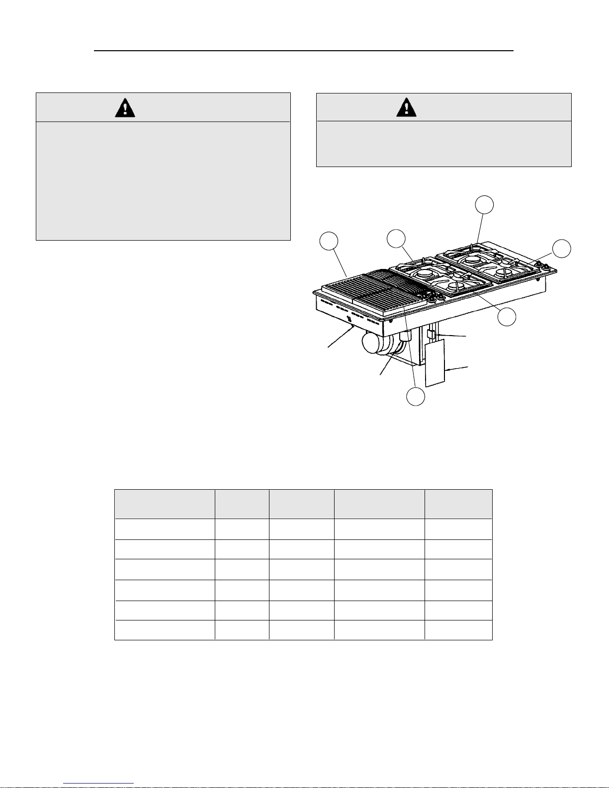
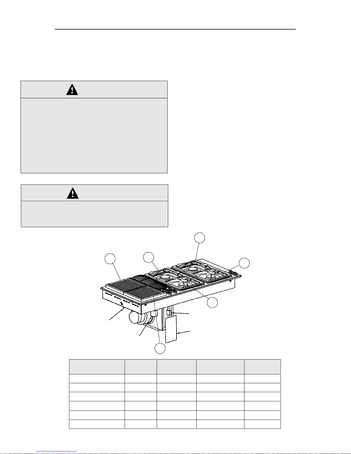
*Blower may berotated for horizontal or vertical direction by loosening nuts around blower inlet. Accessible inside ventilation
chamber.
S NOTICE TO INSTALLER: Leave these instructions with the appliance.
S NOTICE TO CONSUMER: Retain these instructions for future reference.
TIE DOWN BOLT
ON EACH END
BLOWER CAN BE
SWIVELED 90_
GREASE
CONTAINER
29² + 1/16²
73.66 cm
COOKTOP SERIES
JGD8130 & JGD8345
APPLIANCE PRESSURE
REGULATOR
WIRING BOX COVER
BLOWER CAN BE
SWIVELED 90_
21² + 1/16²
53.34 cm
9/16²
7
19.21 cm
TIE DOWN BOLT
ON EACH END
403 WEST FOURTH STREET, NORTH · NEWTON, IA 50208
APPLIANCE PRESSURE
REGULATOR
WIRING BOX COVER
GREASE
CONTAINER
43 1/4² +
109.86 cm
1/16²
21² + 1/16²
53.34 cm
7
9/16²
19.21 cm
15/16²
Min.
Clearance
2.38 cm
SELECT APPROPRIATE
DUCT CUT OUT (SEE
DUCTING INSTALLATION INSTRUCTIONS).
3/8²
9
23.81 cm
13²
33.02 cm
7/8²
1
Min.
4.76 cm
15/16²
Min.
Clearance
2.38 cm
SELECT APPROPRIATE
DUCT CUT OUT (SEE
DUCTING INSTALLATION INSTRUCTIONS).
9
3/8²
23.81 cm
13²
33.02 cm
7/8²
1
Min.
4.76 cm
S Dimension “A” - Provide 2² min. (5.08 cm) cabinet clearance to motor for cooling purpose.
S Note - Where possible, 6² (15.24 cm) is recommended for motor/blower service.
S Side Clearance - Grills installed near a side wall must allow a minimum clearance of 8².
S Access must be provided to remove and empty grease container(s).
INSTRUCTIONS TO INSTALLER
8101P580-60
(04-04-00)
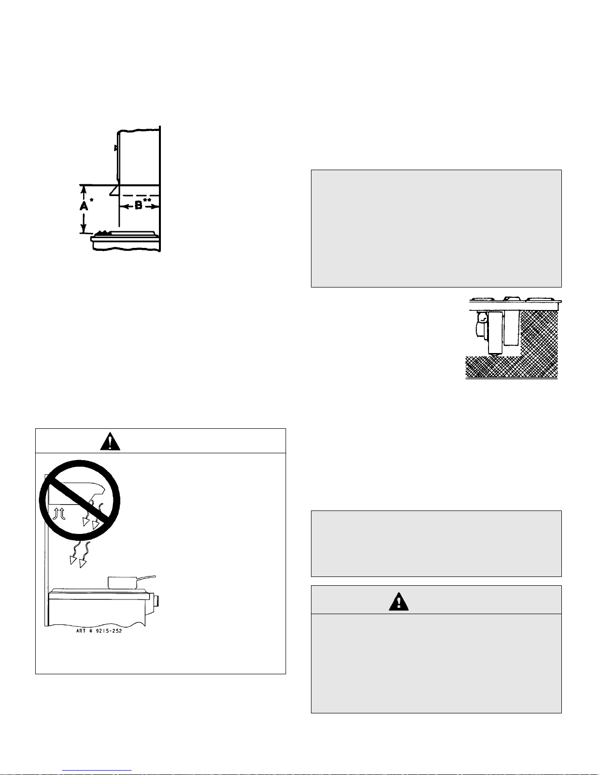
Installing Cabinetry Over Your Jenn-Air Grill
*A = 30² (76.2 cm) minimum vertical clearance between
cooking surface and construction above the
appliance.
*B = 13² (33.02 cm) maximum depth of cabinets installed
above cooking top.
Dotted lines
indicate
range hood
construction
Installation Of Appliance
Follow accompanying ducting instructions carefully.
This appliance is designed to always be vented outdoors.
The Countertop Cutout, Cabinet Front Cutout and Duct
Opening should be prepared according to the illustrations
on pages 1 and 2.
The installation of this appliance must conform with local
codes or, in the absence of local codes, with the latest
edition of the National Fuel Gas Code, ANSI Z223.1 USA
or current CAN/CGA-B149 INSTALLATION CODE.
In The Commonwealth Of Massachu setts
This product must be installed by a licensed plumber or
gas fitter when installed within the Commonwealth of
Massachusetts.
A “T” handle type manual gas valve must be installed in
the gas supply line to this appliance.
* To eliminate associated potential hazards such as
reaching over open flames, avoid use of cabinets above
cooktop for storage space.
Cabinets Above Cooking Top
Maximum depth of cabinets installed above cooking top is
13 inches.
CAUTION: SOME CABINETS AND BUILDING
MATERIALS ARE NOT DESIGNED TO WITHSTAND
THE HEAT PRODUCED BY THE NORMAL SAFE
OPERATION OF A LISTED APPLIANCE.
DISCOLORATION OR DAMAGE, SUCH AS
DELAMINA- TION, MAY OCCUR.
WARNING
THIS PRODUCT SHOULD NOT
BE INSTALLED BELOW A
VENTILATION TYPE HOOD
SYSTEM THAT DIRECTS AIR
IN A DOWNWARD DIRECTION.
(SEE FIGURE)
THESE SYSTEMS MAY CAUSE
IGNITION AND COMBUSTIO N
PROBLEMS WITH THE GAS
BURNERS RESULTING IN
PERSONAL INJURY AND MAY
AFFECT THE COOKING
PERFORMANCE OF THE UNI T.
NOTE: THE FIGURE MAY NOT ACCURATELY REPRESENT
YOUR RANGE OR COOKTOP; HOWEVER, THIS WARNING
APPLIES TO ALL GAS COOKING PRODUCTS.
A flexible gas connector, when used, must not exceed a
length of three (3) feet / 36 inches.
The electrical supply required is
110/120 Volt, A.C., 15 amp, 60
Hz. This appliance is equipped
with a grounded tpe power cord.
A grounded outlet must be provided. It is recommended, for
convenience, this outlet be located in the area shown in the
shaded illustration (see figure 2).
User may experience occasional circuit tripping if Ground
Fault Circuit Interrupter (GFCI) outlet or breaker is in use.
This appliance, when installed, must be electrically
grounded in accordance with local codes or, in the
absence of local codes, with the latest edition of the
National Electrical Code ANSI/NFPA No. 70 USA or
current CSA STANDARD C22.1 Canadian Electrical Code
part 1.
Cabinet Bottom
Figure 2
CAUTION
Warranty is void on JENN-AIR equipment installed other
than as recommended by manufacturer. Recommended
wall caps and transitions must be utilized for proper
operation and installation.
WARNING
ELECTRICAL GROUNDING INSTRUCTIONS
THIS APPLIANCE IS EQUIPPED WITH A
THREE-PRONG GROUNDING PLUG FOR YOUR
PROTECTION AGAINST SHOCK HAZARD AND
SHOULD BE PLUGGED DIRECTLY INTO A
PROPERLY GROUNDED RECEPTACLE. DO NOT
CUTOR REMOVETHEGROUNDING PRONGFROM
THIS PLUG.
2
Connecting Appliance To Gas Supply
WARNING
Gas leaks may occur in your system and result in a
dangerous situation. Gas leaks may not be detected by
smell alone. Gas suppliers recommendyou purchase and
install an UL approved gas detector. Install and use in
accordance with the manufacturer’s instructions.
A QUALIFIED SERVICEMAN OR GAS APPLIANCE
INSTALLER MUST MAKE THE GAS SUPPLY
CONNECTION. Leak testing of the appliance shall be
conducted by the installer according to the
instructions given.
Install a manual shutoff valve in an accessible location in
the gas line external to this appliance for the purpose of
turning on or shutting off gas to the appliance.
Make the gas connection to the inlet to the appliance
pressure regulator on this appliance with a 1/2² male pipe
thread. Use an approved pipe joint compound resistant to
the action of LP gas at pipe connections. Test all joints for
gas leaks with a soap and water solution or other
accepted leak detection means. Never test for gas leaks
with an open flame.
High Altitude Notice
The specified gas burner ratings typically apply to
elevations up to 2000 feet. For higher altitudes, the rates
may need to be reduced to achieve satisfactory operation.
A local certified gas servicer will be able to advise if a
reduction is necessary.
IMPORTANT
Apply a non-corrosive leak detection fluid to all joints and
fittings in the gas connection between the supply line
shut-off valve and the range. Include gas fittings and
joints in the range if connections were disturbed during
installation. Check for leaks! Bubbles appearing around
fittings and connections will indicate a leak. If a leak
appears, turn off supply line gas shut-off valve andretest
for leaks. Never test for gas leaks with an open flame.
Instructions To Installer
1. Chamfer all exposed edges of decorative laminate to
prevent damage from chipping.
2. Radius corners of cutout and file to insure smooth
edges and prevent corner cracking. Recommend
1/4²²²² or 3/8²²²² diameter drill in each corner.
3. Rough edges, inside corners which have not been
rounded and forced fit can contribute to cracking of the
counter top laminate.
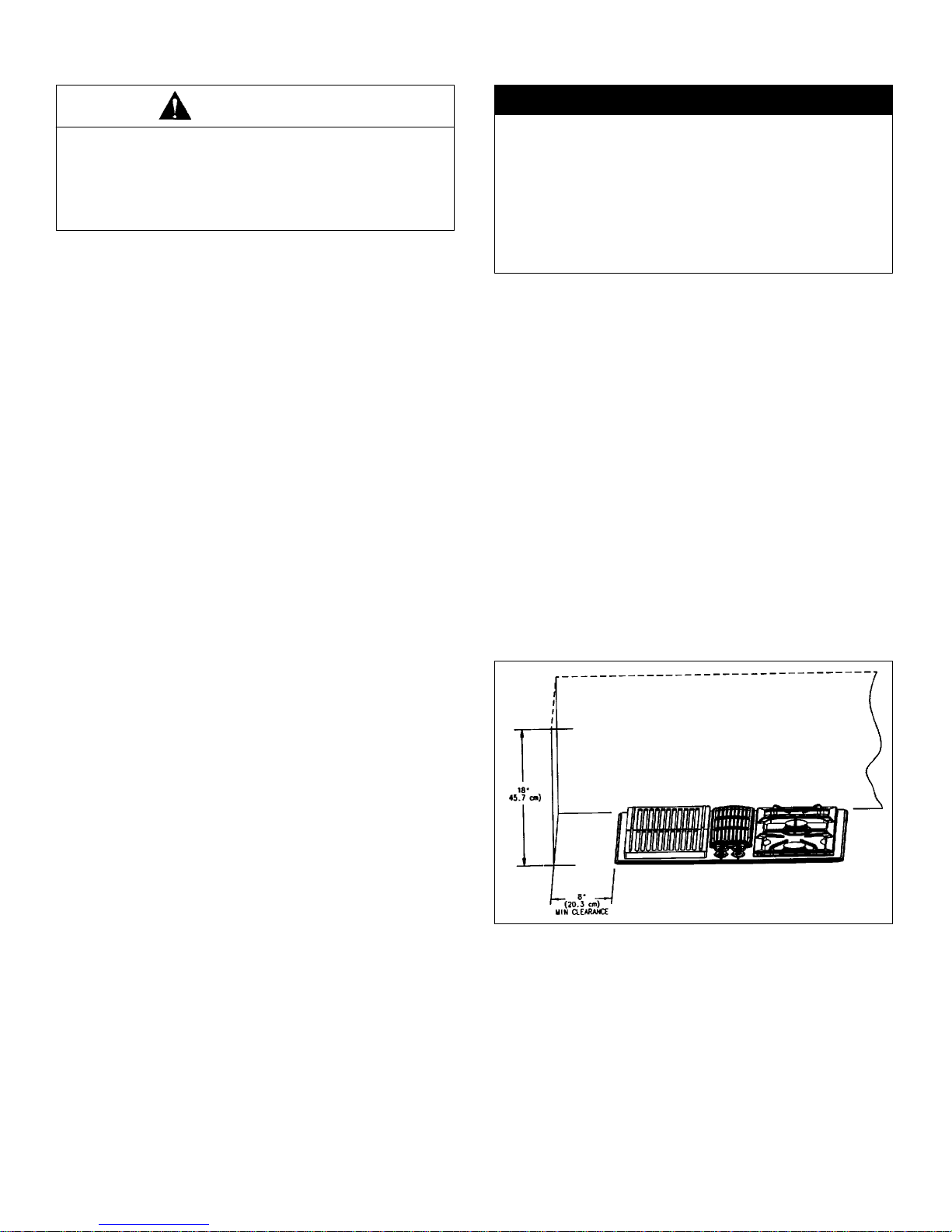
4. Countertop must be supported within 3² of cutout.
Minimum horizontal clearance between the edge of the
appliance and combustible construction extending from
the cooking surface to 18² (45.7 cm) above the cooking
surface is:
15/16² (2.38 cm) at rear
8² at sides
This is not the recommended clearance, but minimum
allowable clearance.
3
Air Shutter Adjustment
This appliance is shipped from the factory with air
shutters adjusted for use with Natural Gas. If further
adjustment is necessary, or to reset for use with LP,
adjust air shutters as follows:
Grill Burner and Surface Burner Cartridge Air
Shutters
The left hand air shutter controls the rear half of the
burner. The right hand shutter controls the front half.
Access to air shutters on the surface burner cartridge may
be found through openings on the bottom of the cartridge
housing.
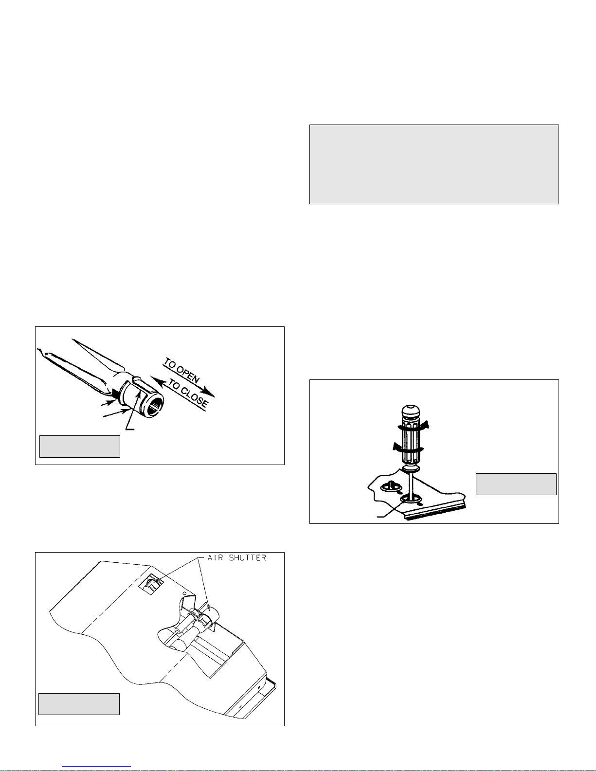
Slide air shutters backward or forward to increase or
decrease the size of the air opening. Air shutters fit
snugly, so a screwdriver blade may be required to make
this adjustment (see illustration).
Observe change in flame appearance as the air shutter is
moved. Adjustment is satisfactory when a clearly defined,
even blue flame results at the high flame setting. The
snug fit of the air shutter assures it will remain positioned
correctly.
(See Illustrations “A” & “B”)
Grill Burner Air Shutter and Surface Burner
(if so equipped)
Low Flame Adjustment (See Illustration “C”)
This appliance is shipped from the factory with low and
medium flame settings adjusted for use with Natural Gas.
If further adjustment is necessary, or to readjust for use
with LP, proceed as follows:
1. Light burner and set control knob for low flame.
2. Remove control knob from valve stem.
CAUTION
NEVER USE A METAL BLADE TO PRY KNOB OFF.
IF KNOB CANNOT BE EASILY REMOVED, TUCK THE
FOLDS OF A CLOTH DISHTOWEL UNDER THE KNOB
AND PULL THE TOWEL UPWARD WITH STEADY,
EVEN PRESSURE.
3. Insert a slender, thin-blade screwdriver into the recess
at center of valve stem and engage blade with slot in
adjusting screw.
4. Turn center stem adjusting screw to set flame size.
S clockwise to reduce.
S counterclockwise to increase.
5. Replace control knob when adjustment is completed.
Proper adjustment will produce a stable, steady blue
flame of minimum size. The final adjustment should be
checked by turning knob from high to low several times
without extinguishing the flame.
This adjustment, at low setting, will automatically provide
the proper flame size at medium setting.
AIR OPENING
AIR SHUTTER
INSERT SCREWDRIVER BLADE IN
ILLUSTRATION
“A”
SLOT AND TWIST WITH SLIGHT
PRESSURE TO ALLOW AIR SHUTTER
TO SLIDE EASILY
On any burner, closing the air shutter too far will cause
the flame to become soft and yellow tipped. Opening the
air shutter too wide will cause the flame to blow away
from the burner ports. Proper adjustment will produce a
sharp, clearly defined, even blue flame.
ILLUSTRATION
“B”
COUNTERCLOCKWISETO
INCREASE FLAME SIZE
CLOCKWISE
TO REDUCE
FLAME SIZE
ILLUSTRATION
“C”
VALVE
STEM
Pressure Testing
The maximum gas supply pressure for the appliance
pressure regulator supplied on this appliance is 14² W.C.
The test pressure for checking this appliance pressure
regulator must be at least 6² W.C. for Natural Gas, and at
least 11² W.C. for LP. It is shipped from the factory set for
Natural Gas at 5² W.C. output pressure.
This appliance and its individual shutoff valve must be
disconnected from the gas supply piping system during
any pressure testing of that system at test pressures in
excess of 1/2² PSIG (3.5 k Pa).
This appliance must be isolated from the gas supply
piping system by closing its individual manual shutoff
valve during any pressure testing of the gas supply piping
system at test pressures equal to or less than 1/2² PSIG
(3.5 k Pa).
4
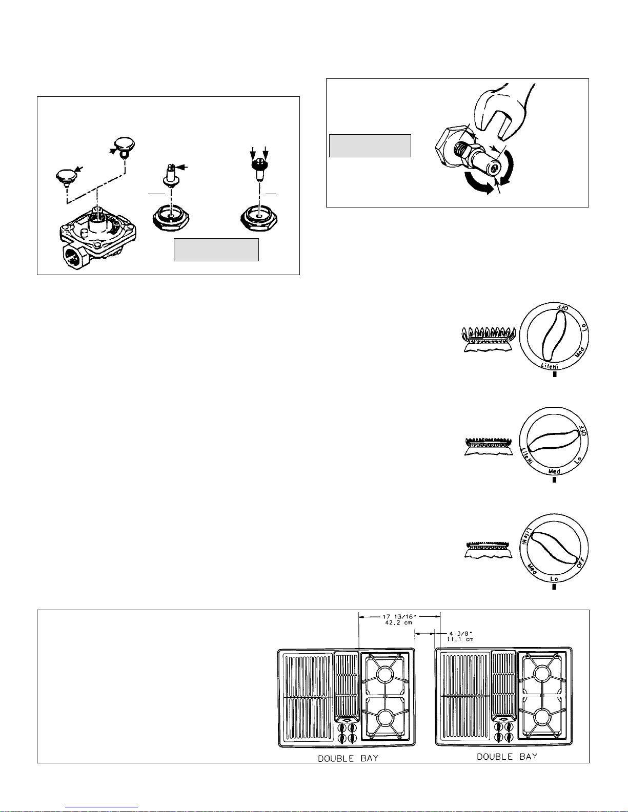
Appliance Pressure Regulator Conversion
(See Illustration “D”)
This unit is supplied with a Maxitrol Appliance Pressure
Regulator. Follow the instructions in illustration “D”.
coded orifice hoods supplied. (See LP Gas Conversion
Instructions above and page 6). TURN CLOCKWISE TO
INSTALL. Hold dimension specified in Illustration “E”.
MAXITROL APPLIANCE PRESSURE REGULATOR
APPLY DOWNWARD
FINGER PRESSURE
AT DISC EDGES TO
REPLACE PIN IN CAP
APPLY
SIDEWARD
FINGER
PRESSURE TO
REMOVE PIN
FROM CAP
NAT
CONVERTER
CAP
AND PIN
LP
NAT LP
ILLUSTRATION
“D”
Conversion To LP Gas
This appliance is shipped from the factory equipped for
use with Natural Gas. To convert it from Natural Gas for
use with LP Gas, perform steps 1 through 4.
1. Remove natural gas orifice hoods. Install color coded
orifice hoods supplied, located in a pack attached to
the outer plenum area of this appliance. (See
Illustration “E”, and LP Gas Conversion Instructions on
page 6).
2. Invert cap in convertible appliance pressure regulator (if
so equipped) located at entrance to gas manifold.
3. Adjust air shutters on individual burners for proper
flame appearance.
4. Adjust low flame setting at each burner by turning
adjustment screw in center of valve stem.
To make these conversion adjustments follow the
instructions and illustrations (“A” through “E” on
pages 4 - 5).
This appliance is shipped from the factory with orifice
hoods drilled for use with Natural Gas. To convert from
Natural Gas to LP, apply a 1/2² open-end wrench to hex
section of orifice hood. TURN COUNTERCLOCKWISE
TO REMOVE. Save the Natural Gas orifice hoods just
removed from this appliance for future use. Install color
1/2² OPEN END
WRENCH
ILLUSTRATION
“E”
TURN
COUNTERCLOCKWISE
TO REMOVE
11/16²²²²
TURN
CLOCKWISE
TO TIGHTEN
ORIFICE HOOD
Control Settings
The size and type of cookware and the amount and type
of food being cooked will influence the setting needed for
best cooking results. The setting indicated should serve
as a guide while you become familiar with your cooktop.
Use the HI flame settingto
quickly bring foods to a boil or
to begin a cooking operation.
Then reduce to a lower
setting to continue cooking.
Never leave food unattended
over a HI flame setting.
Med setting is used to
continue a cooking operation. Food will not cook any
faster when a HI flame
setting is used than that is
needed to maintain a gentle
boil. Remember, water boils
at the same temperature
whether boiling gently or
vigorously.
Use Lo setting to keep food
at serving temperatures
without further cooking. You
may find that some cooking
may take place if the
cookware is covered.
Minimum Spacing Requirement
Convertible Gas Cooktops
For installing a Double Bay Downdraft
Cooktop in combination with another
Downdraft Cooktop, the minimum
spacing between adjacent units must
be provided, as shown, for satisfactory
performance.
5
TO CONVERT APPLIANCE FOR USE WITH PROPANE GAS
Natural Gas To Propane Gas (LP) Conversion Instructions
WARNING
Propane Gas conversion is to be performed by a
Jenn-Air Authorized Service Contractor (or other
qualified agency) in accordance with the
manufacturer’s instructions and all codes and
requirements of the authority having jurisdiction.
Failure to follow instructions could result in serious
injury or property damage. The qualified agency
performing this workassumesresponsibility for this
conversion.
Models - JGD8130 & JGD8345 Series
Manifold - Propane Gas pressure required - 10² W.C.
Incoming Propane Gas pressure required to appliance
pressure regulator - 11² -12² W.C.
Propane Gas conversion orifice hoods are supplied with
these models.
Propane Gas input specified - JGD8130/JGD8345 -
33,000 BTU/hr / 51,000 BTU/hr.
WARNING
ELECTRICAL POWER AND GAS MUST BE
TURNED OFF PRIOR TO CONVERSION
RR
LR
TIE DOWN
BOLT ON
EACH END
GREASE
CONTAINER
CR
LF
CF
APPLIANCE PRESSURE
REGULATOR
WIRING BOX COVER
BLOWER CAN BE
SWIVELED 90_
RF
JGD8345 (Shown)
INCHES
BURNER BTU/hr ORIFICE DIAMETER COLOR
Left Rear (LR) 7,500 #66 .0330 Zinc
Left Front (LF) 7,500 #66 .0330 Zinc
Right Rear (RR) 9,000 #63 .0370 Blue
Right Front (RF) 9,000 #63 .0370 Blue
Center Rear (CR) 9,000 #63 .0370 Blue
Center Front (CF) 9,000 #63 .0370 Blue
6
TO CONVERT APPLIANCE FOR USE WITH NATURAL GAS
Propane Gas (LP) To Natural Gas
Conversion Instructions
If this appliance has been converted for use with LP
Gas, each of the following modifications must be
performed to convert the unit back to Natural Gas.
WARNING
NaturalGas conversion is to be performed by
a Jenn-Air Authorized Service Contractor (or
otherqualifiedagency)inaccordance withthe
manufacturer’sinstructions and all codesand
requirements of the authority having jurisdiction. Failure to follow instructions could r esult
in serious injury or property damage. The
qualified agency performing this work
assumes responsibility for this conversion.
WARNING
ELECTRICAL POWER AND GAS MUST BE
TURNED OFF PRIOR TO CONVERSION
Models - JGD8130 & JGD8345 Series
Manifold - Natural Gas pressure required - 5² W.C.
Incoming Natural Gas pressure required to appliance
pressure regulator - 6² -7² W.C.
Natural Gas input specified, Model JGD8130/JGD8345 -
36,000 BTU/hr / 56,000 BTU/hr.
A. Replace all orifice hoods - Perform steps 1 through 4
on page 4. Locate the (4) four or (2) two Natural Gas
hoods (with small numbers stamped on their sides)
saved from the original Natural Gas unit. Page 5
Illustration “E”. The two hoods with .0520 (#55 orifice)
stamped on them are for the left front and left rear
burners. The two hoods with the .0550 (#54 orifice)
stamped on them are for the two right burners.
To make these conversion adjustments follow the
instructions and illustrations (“A” through “E”)
pages 4 and 5.
B. Invert cap in appliance pressure regulator (see
Illustration “D”). With the appliance installed, the
appliance pressure regulator is located on the center
underside of the appliance at the inlet to the gas
manifold. Identify the type of appliance pressure
regulator on the unit and follow the instructions in the
appropriate illustration.
C. Adjust low flame setting for each burner. Follow the
instructions for burner low flame adjustment on page
4 to increase the simmer flame size.
JGD8345 (Shown)
BURNER BTU/hr ORIFICE DIAMETER COLOR
Left Rear (LR) 8,000 #55 .0520 Brass
Left Front (LF) 8,000 #55 .0520 Brass
Right Rear (RR) 10,000 #54 .0550 Brass
Right Front (RF) 10,000 #54 .0550 Brass
Center Rear (CR) 10,000 #54 .0550 Brass
Center Front (CF) 10,000 #54 .0550 Brass
LR
TIE DOWN
BOLT ON
EACH END
GREASE
CONTAINER
CR
LF
RR
CF
APPLIANCE PRESSURE
REGULATOR
WIRING BOX COVER
BLOWER CAN BE
SWIVELED 90_
INCHES
RF
7
REQUIRED ADJUSTMENTS AT TIME OF INSTALLATION
The installation of this appliance must conform with local codes, or in the absence of local codes, with
thelatesteditionoftheNationalFuelGasCodeANSIZ223.1USAorcurrentCAN/CGA-B149Installation
Code.
Thisrangewas manufacturedforusewithNaturalGas.IfLPgasisthefuelof choice,followtheconversion
to LP procedure found in the installation instructions.
Test all external connections for gas leaks. Never test for gas leaks with an open flame.
Test all electrical connections.
Adjust all air shutters for proper flame.
Adjust all valves for low flame settings.
Test the ventilation system for proper installation.
If a problem exists with the downdraft system, check the ducting installation to make sure it conforms to
the Jenn-Air specifications. Most downdraft system problems are attributed to poor ducting practices.
Contact your installer if the ventilation system will not remove smoke or cooking fumes from well trimmed
cuts of meat.
If ventilation problems persist contact your authorized Jenn-Air Service Contractor.
403 WEST FOURTH STREET, NORTH · NEWTON, IA 50208
 Loading...