

Page 1
CONVERTIBLEGAS GRILL
COOKTOPSERIES
JGD8130 & JGD8345
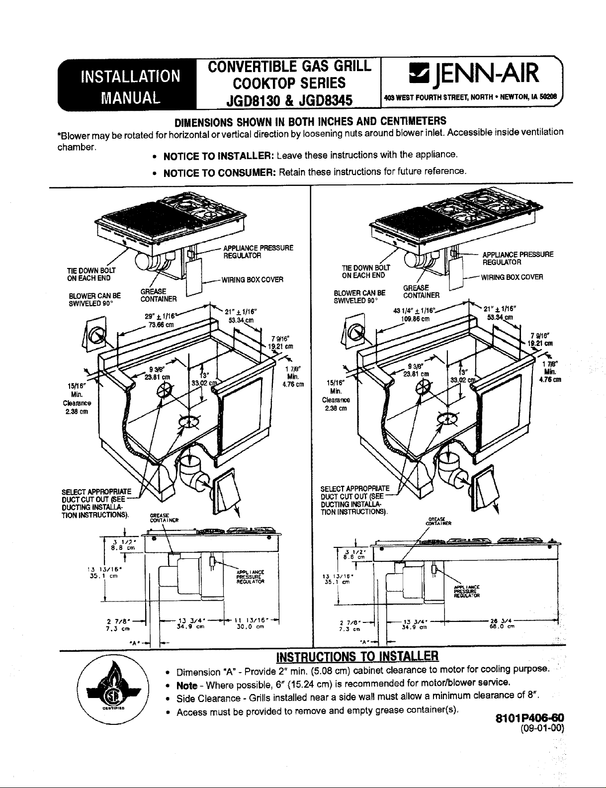
DIMENSIONS SHOWN IN BOTH INCHES AND CENTIMETERS
*Blowermaybe rotated for horizontal or verticaldirection by looseningnuts aroundblowerinlet. Accessible insideventilation
chamber.
• NOTICE TO INSTALLER: Leave these instructions with the appliance.
• NOTICE TO CONSUMER: Retain these instructions for future reference.
JENN-AIR
REGULATOR
TIEDOWNBOLT
ON EACHEND BOXCOVER
BLOWERCANBE CONTAINER
SWIVELED90°
Min.
Cbarar_e
2.38cm
SELECTAPPROPRIATE
DUCTCUTOUT(SEE
DUCTINGINSTALLA-
TIONINSTRUCTIONS). _EAS[
GREASE
29"_1/
CONTA tNER
21"+1116"
7Q/16"
TtEDOWNBOLT
ONEACHEND
BLOWERCANBE CONTAINER
SWIVELED90'=
SELECTAPPROPRIATE
DUCTCUTOUT
DUCTINGINSTALLA-
TIONINSTRUCTIONS).
GREASE
43 114" +lt 21" _- 1/16"
COH_AI_
APPUANCEPRF.SSURE
REGULATOR
79/16"
19.21cm
17_"
Min.
4.76cm
2 7/8 °_ _13 3/4"--,.*_.|t 13/115-_..
7.3 Cm 34.9 cm 30.0 cm
• Dimension"A"- Provide 2" rain. (5.08 cm)cabinetclearance to motorfor coolingpurpose,
• Note - Where possible,6" (15.24 cm) isrecommendedfor motor/blowerservice.
• Side Clearance - Grills installednear a side wall must allow a minimum clearance of8".
• Access must be providedto remove and empty grease container(s),
INSTRUCTIONSTO INSTALLER
8101P406-60
(o9-ol-oO)
/
Page 2
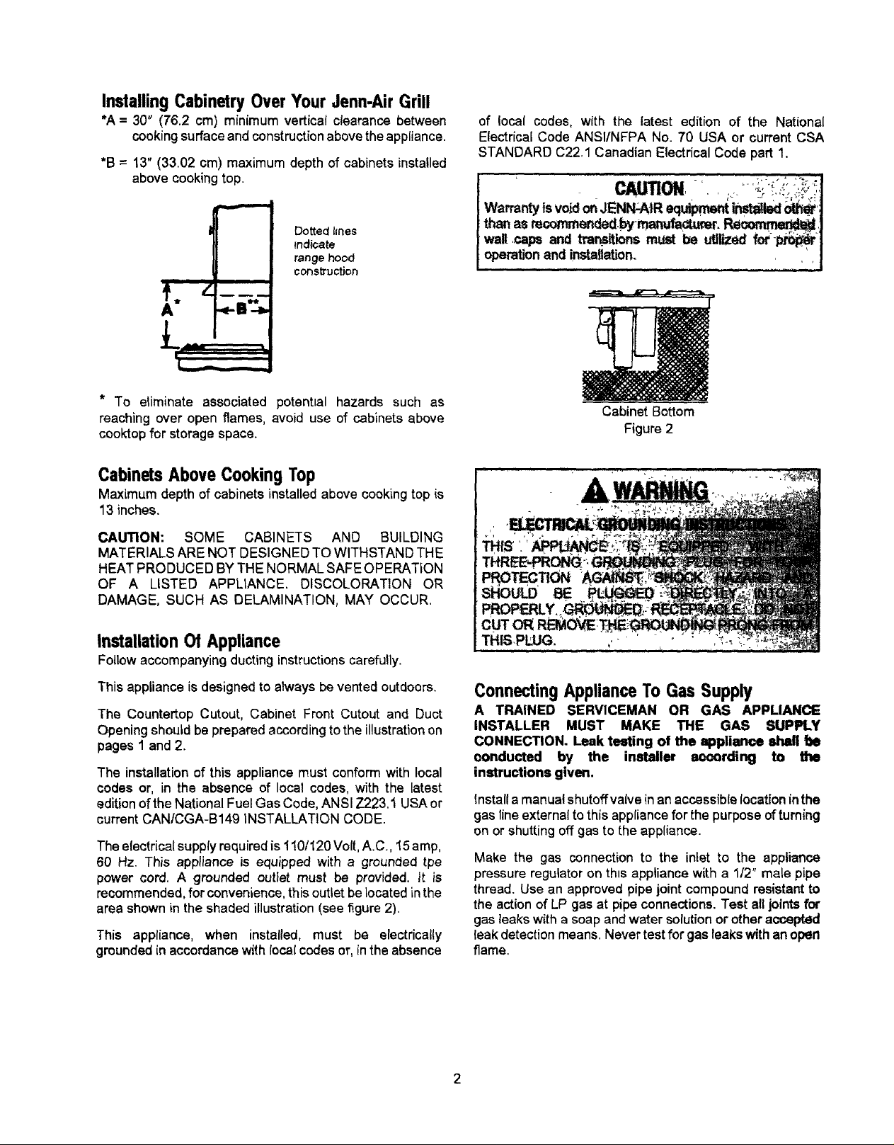
Installing Cabinetry Over Your Jenn-Air Grill
*A = 30" (76.2 cm) minimum verticat clearance between
cooking surface and construction above the appliance.
*B = 13" (33.02 cm) maximum depth of cabinets installed
above cooking top.
Do_edl_nes
tnd_a_
_nge hood
i
construction
* ÷B*_.
(,....-.,_.-_
of local codes, with the latest edition of the National
Electrical Code ANSI/NFPA No. 70 USA or current CSA
STANDARD C22.1 Canadian Electrical Code part 1.
Warranty Isvoid onJEN_AIR equ_rne_ _ _'_l
tt-_ asr_x_nmen_.bymar_fa_. _,]
walt,capsand tr__ _,ns must be _Uzed fot--_ J
operationand installation. ,
f ............ ,:1
* To eliminate associated potential hazards such as
reaching over open flames, avoid use of cabinets above
cooktop for storage space.
Cabinets Above Cooking Top
Maximum depth of cabinets installed above cooking top is
13 inches.
CAUTION: SOME CABINETS AND BUILDING
MATERIALS ARE NOT DESIGNED TO WITHSTAND THE
HEAT PRODUCED BYTHE NORMAL SAFE OPERATION
OF A LISTED APPLIANCE. DISCOLORATION OR
DAMAGE, SUCH AS DELAMINATION, MAY OCCUR.
Installation Of Appliance
Follow accompanying ducting instructions carefully.
This appliance is designed to alwaysbe vented outdoors,
The Countertop Cutout, Cabinet Front Cutout and Duct
Opening should be prepared according to the illustration on
pages 1 and 2.
The installation of this appliance must conform with local
codes or, in the absence of local codes, with the latest
edition of the National Fuel Gas Code, ANSI Z223.1 USA or
current CAN/CGA-B149 INSTALLATION CODE.
The electricalsupplyrequired is 110/120 Volt, A.C., 15 amp,
60 Hz. This appliance is equipped with a grounded tpe
power cord. A grounded outlet must be provided, it is
recommended, for convenience, this outlet be located inthe
area shown in the shaded illustration (see figure 2).
This appliance, when installed, must be electrically
grounded in accordance with local codes or, in the absence
Cabinet Bottom
Figure 2
ConnectingApplianceTo Gas Supply
A TRAINED SERVICEMAN OR GAS APPUANCE
INSTALLER MUST MAKE THE GAS SUPPLY
CONNECTION. Leak teating of the appliance shall f_e
oonducted by the installer aoeording to rite
instructions given.
install a manual shutoffvalve in an accessiblelocation inthe
gas line external to this appliance for the purpose of turning
on or shutting off gas to the appliance.
Make the gas connection to the inlet to the appliance
pressure regulator on this appliancewith a 112" male pipe
thread. Use an approved pipe joint compound resistant to
the action of LP gas at pipe connections. Test alljoints for
gas leaks with a soap and water solution or other accepted
leak detection means. Never test for gas leaks with an open
flame.
Page 3
InstructionsTo Installer
1. Chamfer all exposed edges of decorative laminate to
prevent damage from chipping.
2, Radius corners of cutout and file to insure smooth
edges and prevent corner cracking. Recommend
1/4" or 3/8" diameter drill in each corner,
3. Rough edges, inside comers which have not been
rounded and forced fit can contribute to cracking of the
counter top laminate.
4. Countertop must be supported within 3" of cutout.
Minimum horizontal clearance between the edge of the
appliance and combustible construction extending from the
cookingsurface to 18" (45,7 cm) above the cooking surface
is:
15116"(2.38 cm) at rear
8" at sides
This is not the recommended clearance, but minimum
allowable clearance.
Nr Shutter Adjustment
This appliance is shipped from the factory with air shutters
adjusted for use with N=ural Gas. If further adjustment is
necessary, or to reset for use with LP, adjust air shutters as
follows:
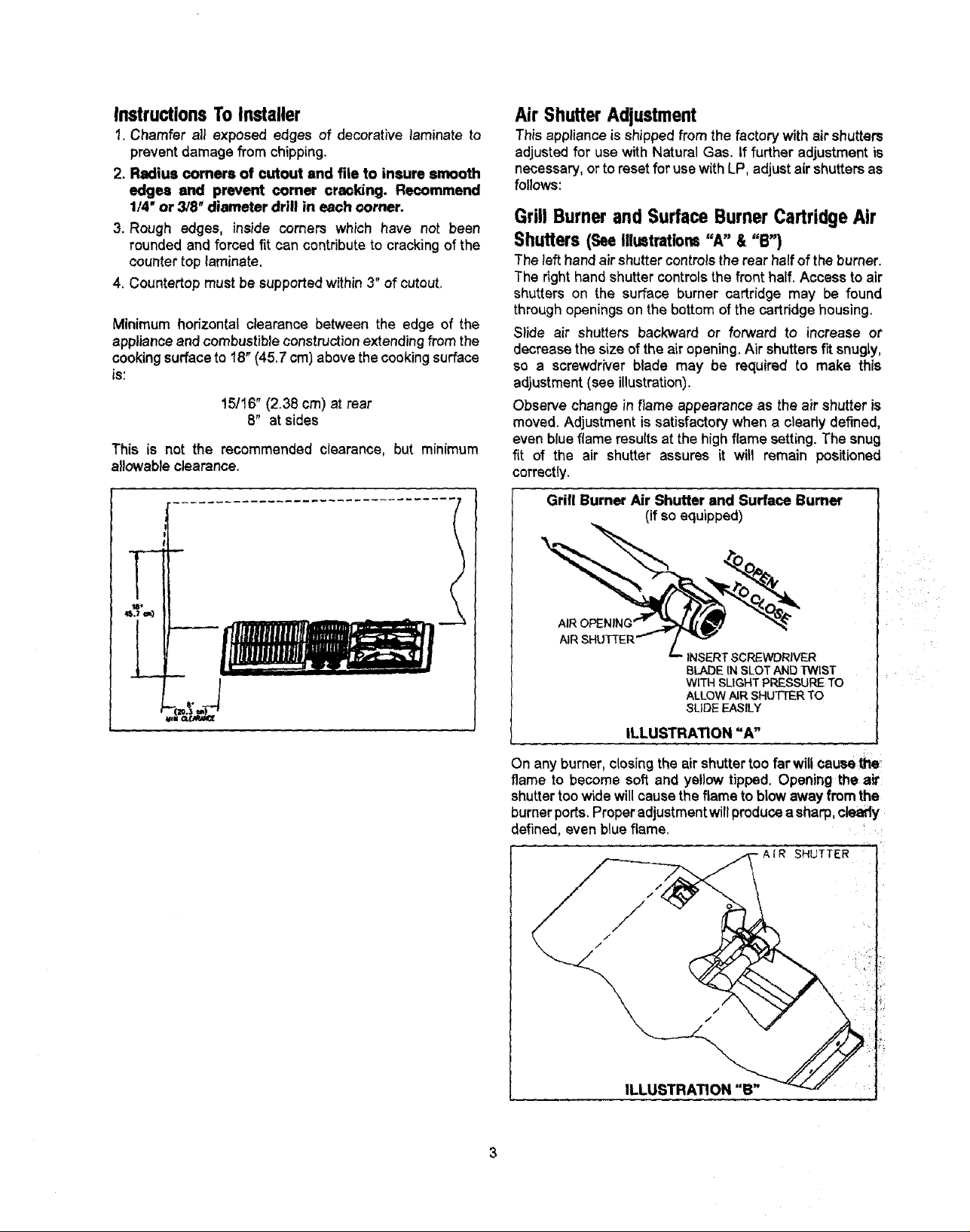
Grill Burner and Surface Burner Cartridge Air
Shutters (SeeIllustrations"A" &"B")
The lefthand air shuttercontrols the rear half of the burner.
The right hand shutter controlsthe front half. Access to air
shutters on the surface burner cartridge may be found
through openings on the bottom of the cartridge housing.
Slide air shutters backward or forward to increase or
decrease the size of the air opening. Air shutters fit snugly,
so a screwdriver blade may be required to make this
adjustment (see illustration).
Observe change in flame appearance as the air shutter is
moved. Adjustment is satisfactory when a cleady defined,
even blue flame results at the high flame setting. The snug
fit of the air shutter assures it will remain positioned
correctly.
Grill Burner Air Shutter end Surface Bumer
(if so equipped)
AIR
INSERT SCREWDRIVER
BLADE IN SLOT AND TWIST
WITH SLIGHT PRESSURE TO
ALLOW AIR SHUTTER TO
SLIDE EASILY
ILLUSTRATION "A"
On any burner, closingthe air shuttertoo far wiltcausethe
flame to become soft and yellow tipped. Opening the air
shutter too wide will causethe flame to blow away from the
burner ports. Proper adjustmentwill produce a sharp,clearly
defined, even blue flame.
-A{R SHUTTER
ILLUSTRATION "B"
Page 4

Low Flame Adjustment (SeeIllustration"C")
This appliance is shipped from the factory with low and
mediumflame settingsadjustedforusewithNaturalGas. If
furtheradjustment is necessary, orto readjustforusewith
LP, proceed as follows:
1. Light burner and set control knob for low flame.
2. Remove control knob from valve stem.
, CAUTION
_EVER_USE A METAL BLADE TO PRY KNOB OFF.
LE_"CAN_DT BE EASILY REMOVED, TUCK THE
_FA_ -C-LOTHDISHTOWEL UNDER THE,KNOB
_D._LoTHE TOWEL UPWARD WITH STEADY,
i i i i i '11 i i i ii ,,, " i ' if
3. Inserta slender, thin-bladescrewdriver into the recess at
center of valve stem and engage blade w_th slot in
adjusting screw.
4. Turn center stem adjusting screw to set flame size.
• clockwise to reduce.
• counterclockwise to increase.
5, Replace control knob when adjustment is completed.
Proper adjustmentwillproducea stable, steady blue flame
of minimum size. The final adjustmentshould be checked by
turning knob from high to low several times without
extinguishing the flame
PressureTesting
The maximum gas supply pressure for the appliance
pressure regulator suppliedonthis appliance is 14" W.C.
The test pressure for checking this appliance pressure
regulator must be at least 6" W.C. for Natural Gas, and at
least 11" W.C for LP. It is shipped from the factory set for
Natural Gas at 5" W.C. output pressure
This appliance and its individual shutoff valve must be
disconnected from the gas supply piping system during any
pressure testing of that system at test pressures in excess
of 112"PSIG (3.5 k Pa)
This appliance must be isolated from the gas supply piping
system by closingits individual manual shutoffvalve during
any pressuretesting of the gas supply piping system at test
pressures equal to or less than 112"PSIG (3.5 k Pa).
Appliance Pressure Regulator Conversion
(See Illustration"D")
This unit is supplied with a Maxitrol Appliance Pressure
Regulator Follow the instructions in illustration=D".
MAXITROL APPLIANCE PRESSURE REGULATOR
APPLY DOWhhNARD
FINGER PRESSURE
This adjustment, at low setting, willautomatically provide the
proper flame size at medium setting.
COUNTERCLOCKWISE TO
INCREASE FLAME SIZE
CLOCKWISE
TO REDUCE
FLAME SIZE
VALVE
ILLUSTRATION "C"
N.A,_"AN D PJN._'" NAT_I'- !ilEG_EWR_RETO
ILLUSTRATION "D"
Page 5

ConversionToLP Gas
This applianceis shippedfrom the factory equipped for use
with Natural Gas. To convert it from Natural Gasfor usewith
LP Gas, perform steps 1 through 4.
1. Remove natural gas orifice hoods. Install color coded
orifice hoods supplied, located in a pack attached to the
outer plenum area of this appliance. (See illustration "E"
below, and LP Gas Conversion Instructions on page 6).
2. Invert cap in convertible appliance pressure regulator (if
so equipped) located at entrance to gas manifold.
3. Adjust air shutterson individual burners for proper flame
appearance.
4. Adjust low flame setting at each burner by turning
adjustment screw in center of valve stem.
To make these conversion adjustments follow the
instructions and illustrations ("A" through "E" on
pages 3 - 4).
iApply a non-corrosive leak detection fluid to alljoints and
fittings in the gas connection between the supply fine
shut-off valve and the range. Include gas fittings and
joints in the range if connections were disturbed during
installation. Check for leaks! Bubbles appearing around
fittings and connections will indicate a leak. If a leak
appears, turn off supply hnegas shut-off valve and retest
for leaks. Never test for gas leaks with an open flame.
This applianceis shippedfrom the factorywith orifice hoods
ddlledfor usewithNatural Gas. Toconvertfrom Natural Gas
toLP,applya 1/2"open-endwrenchto hexsectionoforifice
hood.TURN COUNTERCLOCKWISE TO REMOVE. Save
the Natural Gas orifice hoods just removed from this
appliance for future use. Instatl color coded odfice hoods
supplied. (See LP Gas Conversion Instructions above and
page 6). TURN CLOCKWISE TO INSTALL. Hold dimension
specifiedin Illustration"E".
I_OPEN END
WRENCH
TURN
CLOCKWISE
TURN
COUNTERCLOCKWISE
TO REMOVE ORIFICE HOOD
iLLUSTRATION "E"
TO TIGHTEN
ControlSettings
The size and type ofcookwara and the amount and type of
food beingcookedwi(Iinfluence the settingneeded forbest
cookingresults. The setting indicated should serve as a
guide whileyou become familiar with your cooktop.
Use the HI flame setting to
quickly bringfoods toa boilor
to begin a cooking operation.
Then reduce to a lower
setting to continue cooking.
Never leave food unattended
over a HI flame setting.
Mad setting is used to
continue a cooking opera-
tion. Food will not cook any
faster when a HI flame
setting is used than that is
needed to maintain a gentle
boil. Remember, water boils
at the same temperature
whether boiling gently or
vigorous},/.
Use Lo setting to keep food
at serving temperatures
withoutfurther cooking. You
may find that some cooking
may take place if the
cookware is covered.
|
I
Minimum Spacing Requirement
Convertible Gas Cooktops
For installing a Double Bay Downdraft
Cooktop in combination with another
Downdraft Cooktop, the minimum spacing
between adjacent units must be provided, as
shown, for satisfactoryperformance.
DOUBLE BAY
DOUBLE BAY
Page 6

TO CONVERTAPPLIANCEFORUSE WITH PROPANEGAS
Natural Gas To Propane Gas (LP) ConversionInstructions
...,, .
F.LECTmCAL e, S.UST
__ Authorized Service Contractor (or
otherqualifiedagency) in accordancewith the
_man_s:!nstructlons anda, codesand
='_uL_'n_, ,of _the , authority having
u_o_ Failure to follow instructions could
.,_ult_ serious "injury or property damage. The
_ualif!_ agency performing this work assumes
responsibility for this conversion.
r
Models - JGD8130 & JGD8345 Series
Manifold - Propane Gas pressure required - 10" W.C.
Incoming Propane Gas pressure required to appliance
pressureregulator- 11" - 12" W,C.
Propane Gas conversionorifice hoods are suppliedwith
these models•
Propane Gas input specified - JGD8130/JGD8345 -
33,000 BTUthr / 51,000 BTU/hr.
TURNEDOFFPRIOR.TOC0¢__:' r_,
TIE DOWN
BOLT ON
EACH END
GREASE
CONTAINER
®
REGULATOR
BLOWERCANBE
SWIVELED90°
JGD8345(Shown)
INCHES
BURNER BTU/hr ORIFICE DIAMETER COLOR
Left Rear(LR) 7,500 #66 .0330 Zinc
Left Front (LF) 7,500 #66 .0330 Zinc
Right Rear (RR) 9,000 #63 .0310 Blue
Right Front (RF) 9,000 #63 .0370 Blue
Center Rear (CR) 9,000 #63 .0370 Blue
Center Front (CF) 9,000 #63 .0370 Blue
Page 7

TO CONVERTAPPLIANCEFOR USEWITH NATURALGAS
Propane Gas (LP) To Natural Gas
Conversion Instructions
If this appliance has been convertedfor usewith LP Gas,
each of the following modifications must be performed to
convert the unit back to Natural Gas
'_Natur_GascOnverslonistobeperformed,bya
3e_.ir /Authorized Service Contractor (or
_,er:qua!ifiedagency) in accordancewiththe
__._s instructionsandallcodesand
_Ve_l=_metlts_ :-of ,the authority , having
_dsdtcti0p,' F_Um to follow instructions could
__i_ury rOrproperty damage. The
___o_ng t_ work_ornes
o , -
'__"RAJmv'GASrareSTeE
Models - JGD8130 & JGD8345 Series
Manifold - Natural Gas pressure required - 5" W.C.
Incoming Natural Gas pressure required to appliance
pressure regulator - 6" - 7" W.C.
Natural Gas input specified, Model JGD8130/JGD8345 -
36,000 BTU/hr / 56,000 BTU/hr.
A. Replace al!orificehoods- Perform steps 1through 4 on
page4 Locatethe (4)four or (2)two Natural Gas hoods
(with small numbers stamped on their sides) saved
from the original Natural Gas unit. Page 4 Illustration
"E". The two hoods with .0520 (#55 orifice) stamped on
them are for the left front and left rear burners. The two
hoods with the .0550 (#54 odfice) stamped on them are
for the two right burners.
To make these conversion adjustments follow the
instructions and illustrations ("A" through "E") pages
3 and 4.
B. invert cap in appliance pressure regulator (see
Illustration "D"). With the appliance installed, the
appliance pressure regulator is located on the center
underside of the appliance at the inlet to the gas
manifold. Identify the type of appliance pressure
regulator on the unit and follow the instructionsin the
appropriate Illustration.
C. Adjust low flame setbng for each bumer. Follow the
instructions for burner low flame adjustment on page 4
to increasethe simmerflame size.
JGD8345 (Shown)
BURNER BTU/hr ORIFICE DIAMETER COLOR
Left Rear (LR) 8,000 #55 .0520 Brass
Left Front(LF) 8,000 #55 0520 Brass
Right Rear (RR) 10,000 #54 .0550 Brass
RightFront (RF) 10,000 #54 .0550 Brass
Center Rear (CR) 10,000 #54 .0550 Brass
Center Front (CF) 10,000 #54 .0550 Brass
TIEDOWN
BOLTON
EACHEND
GREA3E
CONTAINER
®
REGULATOR
INCHES
PRESSURE
BLOWERCANBE
SWIVELED90o
Page 8

REQUIREDADJUSTMENTSAT TIME OF INSTALLATION
The installation of this appliance must conform with local codes, or in the absence of local codes, with
the latest edition of the National Fuel Gas CodeANSI Z223.1 USA or current CAN/CGA-B149 Installation
Code.
-'-']This range was manufactured for use with Natural Gas. If LP gas is the fuel of choice, follow the conversion
to LP procedure found in the installation instructions.
----] Test all external connections gas leaks. Never test for gas leaks with an open flame.
----] Test all electrical connections.
Adjust all air shutters for proper flame.
Adjust all valves for low flame settings.
Test the ventilation system for proper inst_llation.
lf a problem exists with the downdraft system, check the ducting installation to make sure it conforms tc
the Jenn-Air specifications. Most downdraft system problems are attributed to poor ducting practices.
for
Contact your installer if the ventilation system will not remove smoke or cooking fumes from well trimmed
cuts of meat.
If ventilation problems persist contact your authorized Jenn-Air Service Contractor.
ZJENN-AIR
4_ WEST FOURTH STREET, NORTH • NEWTON, IA 50208
 Loading...