

Jenn-Air JGD3430B Dimension Manual
JENN-AIR® DETAILED PLANNING DIMENSIONS
A
A
B
I
J
E
B
JENN-AIR® DETAILED PLANNING DIMENSIONS
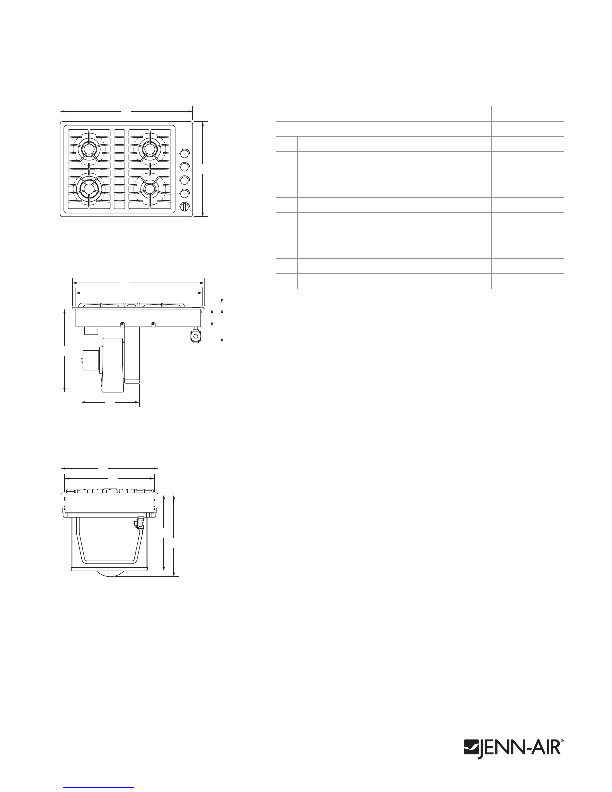
30" JX3™ GAS DOWNDRAFT COOKTOP
JGD3430B – 30" x 183⁄8" x 211⁄2"
PRODUCT DIMENSIONS
MODEL # JGD3430B
Overall width 30 76.2
A
Overall depth 211⁄2 54.6
B
Width of recessed cooktop 283⁄8 72.1
C
Width of blower motor assembly 121⁄2 31.8
D
Height from blower motor to countertop 183⁄8 46.8
E
Height of recessed cooktop 4 10.2
F
Height with grates 13⁄8 3.4
G
Height from gas inlet to countertop 73⁄4 19.8
H
Depth of recessed cooktop 193⁄4 50.0
I
Height from plenum to countertop 167⁄8 42.8
J
TOP VIEW
B
A
C
G
1 of 4
in cm
E
FRONT VIEW
SIDE VIEW
F
H
D
B
I
J
E
Product dimension, cutout and installation specifications are provided for planning purposes only. Before installing
any product, be sure to verify cutout dimensions and electrical/gas connections as actual product dimensions may vary.
7778AdZw613
JENN-AIR® DETAILED PLANNING DIMENSIONS
E*
F
D
e
A
BB
v
H
G
C
I
L
BB
M
Side
Cabinet
JENN-AIR® DETAILED PLANNING DIMENSIONS
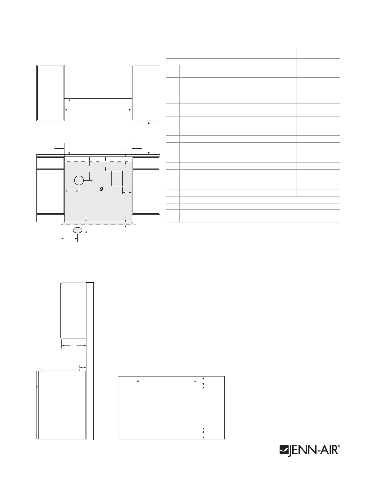
30" JX3™ GAS DOWNDRAFT COOKTOP
JGD3430B – 30" x 183⁄8" x 211⁄2"
2 of 4
OPENING/CLEARANCE DIMENSIONS
A
E*
H
FRONT VIEW
G
v
C
J**
v
C
I
e
D
K
MODEL # JGD3430B
in cm
Width of combustible area above cooking
A
surface (min.)
Width from cooktop to fixed wall or other
B
combustible material (min.)
Width to center of vent opening option 81⁄2 21.6
C
Width to outer edge of outlet 10 25.4
D
Height to bottom of uncovered wood or metal
E*
cabinet above cooking surface (min.)
Height to bottom of uncovered wood or metal
F
cabinet (min.)
Height to center of vent opening option 16 40.6
F
G
Height to top edge of outlet (min.) 12 30.5
H
Height to top of gas installation area 6 15.2
I
Depth to center of vent opening option 171⁄8 43.5
J**
Depth of gas installation area 6 15.2
K
Depth of upper cabinet (recommended) 13 33.0
L
Depth from cutout to wall (min.) 2 5.1
M
Width of cutout 285⁄8 72.7
N
Depth of cutout 20 50.6
O
Depth from cutout to front of countertop 21⁄8 5.4
P
e
Recommended electrical access location
g
Recommended gas supply line location
Recommended venting location –
v
see pages 3-4 for ducting information
* Dimension can be reduced by 6" (15.2 cm) when bottom of wood or metal
cabinet is covered by not less than 1⁄4" (0.6 cm) flame retardant millboard
covered with not less than No. 28 MSG sheet metal, 0.015" (0.4 mm) stainless
steel, 0.024" (0.6 mm) aluminum or 0.020" (0.5 mm) copper.
**Based on installation in a 24" deep (61.0 cm) base cabinet.
30 76.2
6 15.2
30 76.2
18 45.7
Side
Cabinet
L
M
SIDE VIEW TOP VIEW
Product dimension, cutout and installation specifications are provided for planning purposes only. Before installing
any product, be sure to verify cutout dimensions and electrical/gas connections as actual product dimensions may vary.
GAS REQUIREMENTS
Natural Gas
This cooktop is factory-set for use with natural gas.
LP Gas Conversion
Conversion must be done by a qualified service technician. To convert to LP gas, use
the LP gas conversion kit provided with the cooktop.
ELECTRICAL REQUIREMENTS
120 volt, 60 Hz, AC only, 15-amp fused, electrical circuit is required. A time-delay
fuse or dedicated circuit is recommended.
VENTING REQUIREMENTS
This cooktop must be exhausted outdoors unless using the duct-free filter kit
(JDA7000WX). Refer to kit instructions for further information.
LOCATION REQUIREMENTS
• To ensure cooktop base clearance, cabinet side walls need to be wider than the cutout.
• A minimum clearance of 2" (5.1 cm) is recommended between the blower motor and
cabinet for proper cooling. A 6" (15.2 cm) clearance is recommended for servicing access.
• An under counter built-in oven cannot be installed under this cooktop.
N
M
O
P
7778AdZw613
 Loading...