

Jenn-Air JGC3115GS0, JGC3215GS0 Installation Guide
15" (38.1 CM) GAS COOKTOP
IMPORTANT:
Installer:
Homeo
IMPOR
Installateur
Pr
.
INSTALLATION INSTRUCTIONS
INSTRUCTIONS D’INSTALLATION DE TABLE
DE CUISSON À GAZ DE 15" (38,1 CM)
Table of Contents/Table des matières
COOKTOP SAFETY ........................................................................1
INSTALLATION REQUIREMENTS .................................................3
Tools and Parts .............................................................................3
Location Requirements ................................................................3
Electrical Requirements ...............................................................5
Gas Supply Requirements ...........................................................5
INSTALLATION INSTRUCTIONS ...................................................7
Prepare Cooktop for Installation ..................................................7
Install Cooktop .............................................................................7
Make Gas Connection .................................................................8
Complete Installation ...................................................................9
COOKTOP SAFETY
SÉCURITÉ DE LA TABLE DE CUISSON .....................................11
EXIGENCES D’INSTALLATION ...................................................12
Outillage et pièces ......................................................................12
Exigences d’emplacement .........................................................12
Spécications électriques ..........................................................14
Spécications de l’alimentationen gaz .....................................15
INSTRUCTIONS D’INSTALLATION ............................................. 16
Préparation de la table de cuisson pour l’installation ................16
Installation de la table de cuisson ..............................................16
Raccordement au gaz ................................................................17
Achever l’installation ..................................................................18
Your safety and the safety of others are very important.
We have provided many important safety messages in this manual and on your appliance. Always read and obey all safety
messages.
This is the safety alert symbol.
This symbol alerts you to potential hazards that can kill or hurt you and others.
All safety messages will follow the safety alert symbol and either the word “DANGER” or “WARNING.”
These words mean:
You can be killed or seriously injured if you don't immediately
DANGER
WARNING
All safety messages will tell you what the potential hazard is, tell you how to reduce the chance of injury, and tell you what can
happen if the instructions are not followed.
Leave installation instructions with the homeowner.
wner: Keep installation instructions for future reference.
follow instructions.
You
can be killed or seriously injured if you don't
instructions.
follow
opriétaire : Conserver les instructions d'installation pour référence ultérieure
W11030506D
TANT :
: Remettre les instructions d'installation au propriétaire.
WARNING: If the information in this manual is not followed exactly, a fire or explosion
IMPORTANT: Do not install a ventilation system that blows air downward toward this gas cooking appliance. This type of
ventilation system may cause ignition and combustion problems with this gas cooking appliance resulting in personal injury or
unintended operation.
may result causing property damage, personal injury or death.
– Do not store or use gasoline or other flammable vapors and liquids in the vicinity of this
or any other appliance.
– WHAT TO DO IF YOU SMELL GAS:
Do not try to light any appliance.
•
Do not touch any electrical switch.
•
Do not use any phone in your building.
•
Immediately call your gas supplier from a neighbor's phone. Follow the gas supplier's
•
instructions.
If you cannot reach your gas supplier, call the fire department.
•
– Installation and service must be performed by a qualified installer, service agency or
the gas supplier.
WARNING: Gas leaks cannot always be detected by smell.
Gas suppliers recommend that you use a gas detector approved by UL or CSA.
For more information, contact your gas supplier.
If a gas leak is detected, follow the “What to do if you smell gas” instructions.
In the State of Massachusetts, the following installation instructions apply:
Installations and repairs must be performed by a qualified or licensed contractor, plumber, or gas fitter qualified or licensed by
the State of Massachusetts.
Acceptable Shut-off Devices: Gas Cocks and Ball Valves installed for use shall be listed.
A flexible gas connector, when used, must not exceed 4 feet (121.9 cm).
2
INSTALLATION REQUIREMENTS
Tools and Parts
Gather the required tools and parts before starting installation.
Tools needed
■ Tape measure
■ Flat-blade screwdriver
■ #2 Phillips screwdriver
15
■
/16" combination wrench
■ Pipe wrench
Parts supplied
■ Gas pressure regulator
■ Burner grates (1)
■ Burner bases:
Single burner units (1)
Double burner units (2)
■ Burner caps (2)
■ Clamp brackets (2)
1
■ 2
/2" clamping screws (2)
■ Foam tape seal
■ Propane conversion kit - W11027216
■ Mounting bridge kit: W11031680”
■ Channel lock pliers
■ Marker or pencil
■ Pipe-joint compound
resistant to Propane gas
■ Noncorrosive leak-
detection solution
The installation of this cooktop must conform to the
Manufactured Home Construction and Safety Standard, Title 24
CFR, Part 3280 (formerly the Federal Standard for Mobile Home
Construction and Safety, Title 24, HUD Part 280). When such
standard is not applicable, use the Standard for Manufactured
Home Installations, ANSI A225.1/NFPA 501A, or local codes.
In Canada, the installation of this cooktop must conform with
thecurrent standards CAN/CSA-A240 - latest edition, or with
local codes.
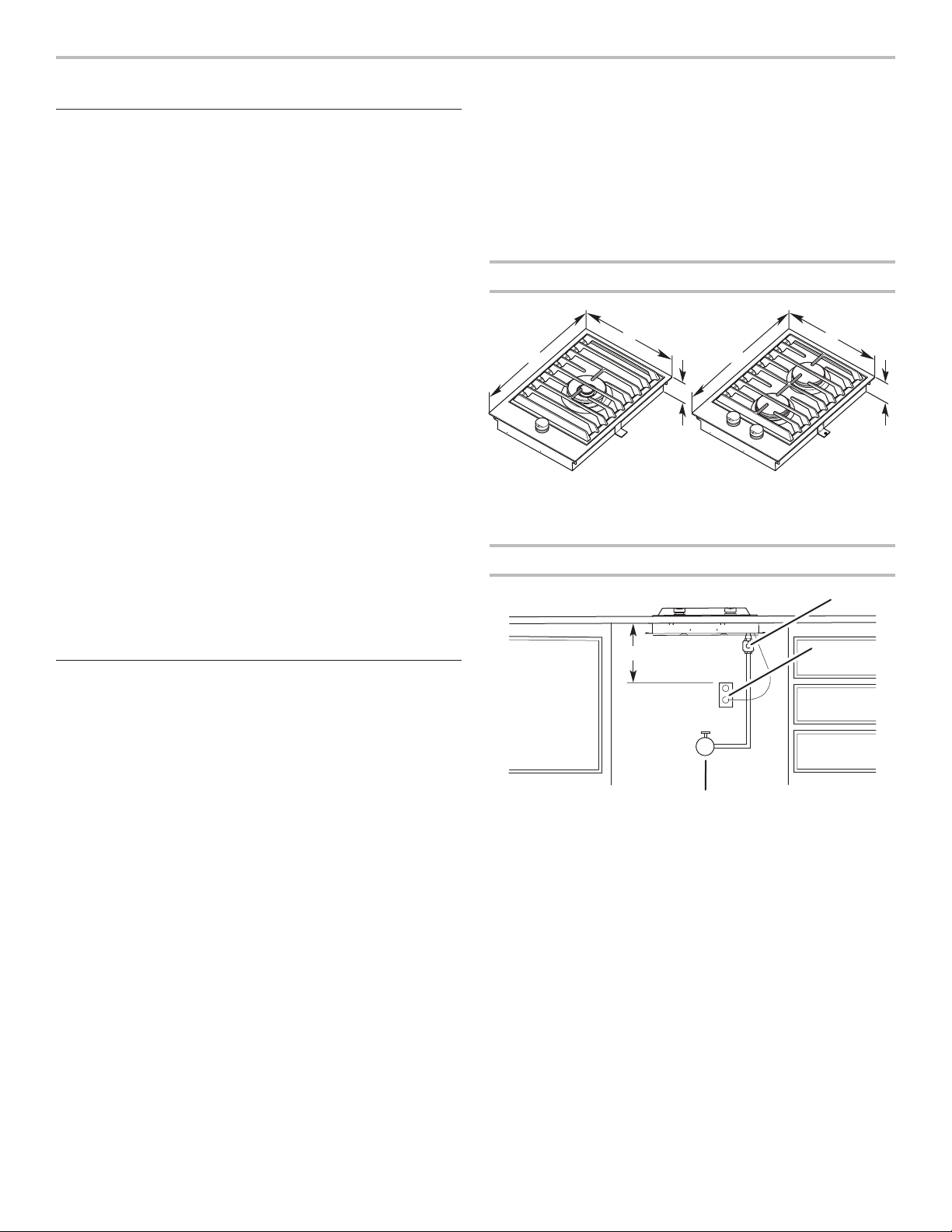
Product Dimensions
B
A
A
C
A. 21" (53.3 cm)
B. 15" (38.1 cm)
C. 31/4" (8.3 cm)
B
Gas and Electric Connection Locations
C
Parts needed
Check local codes and consult gas supplier. Check existing gas
supply and electrical supply. See the “Electrical Requirements”
and “Gas Supply Requirements” sections.
Location Requirements
IMPORTANT: Observe all governing codes and ordinances.
Donot obstruct ow of combustion and ventilation air.
■ It is the installer’s responsibility to comply with installation
clearances specied on the model/serial/rating plate. The
model/serial/rating plate is located on the underside of the
cooktop burner box.
■ Do not unpack the burner grate and base(s) until after the
cooktop is installed to avoid scratching the cooktop.
■ The cooktop should be installed in a location away from
strong draft areas, such as windows, doors, and strong
heating vents or fans.
■ All openings in the wall or oor where cooktop is to be
installed must be sealed.
■ Cabinet opening dimensions that are shown must be used.
Given dimensions are minimum clearances.
■ Grounded and polarized electrical supply is required. See the
“Electrical Requirements” section.
■ Proper gas supply connection must be available. See the
“Gas Supply Requirements” section.
■ The gas and electric supply should be located as shown in
“Gas and Electric Connection Locations” in the “Location
Requirements” section so that they are accessible without
requiring removal of the cooktop.
IMPORTANT: To avoid damage to your cabinets, check with
your builder or cabinet supplier to make sure that the materials
used will not discolor, delaminate, or sustain other damage.
A
D
B
C
A. Gas pressure regulator (supplied)
- arrow pointed toward cooktop
B. 3 prong grounding type outlet
with correct polarity
C. Gas shut-off valve
D. 18" (45.7 cm) minimum
NOTE: Each unit must have a separate regulator (supplied).
Mobile Home - Additional Installation Requirements
3
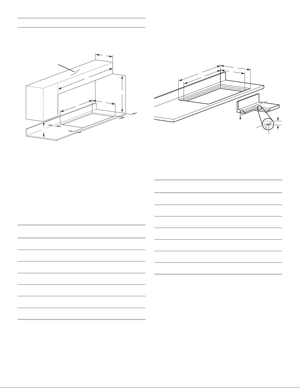
Installation Clearances
IMPORTANT: If installing a range hood or microwave hood
combination above the cooking surface, follow the range hood
or microwave hood combination installation instructions for
dimensional clearances above the cooktop surface.
D
B
C
F
I
J
Flush Installation Dimensions
All cooktops can be mounted with a frameless standard
installation sitting on top of the countertop surface or ush
with the top of the countertop. If the cooktop is to be mounted
ush with the countertop, a 11/64”(4.3 mm)-deep recessed
area surrounding the cooktop cutout must be provided with the
following dimensions.
NOTE: This option is not recommended for countertops with a
molded backsplash. Do not silicone seal in place.
A
D
C
B
F
E
A
A. 18" (45.7 cm) minimum clearance upper cabinet to countertop
B. Cabinet
C. See the Multi-Unit Dimensions table.
D. 13" (33 cm) maximum recommended upper cabinet depth
E. 6" (15.2 cm) minimum side wall clearance
F. 30" (76.2 cm) minimum clearance between top of cooktop platform
and bottom of uncovered wood or metal cabinet (24" [61 cm]
minimum clearance if bottom of wood or metal cabinet is covered by
not less than 1/4" [0.6 cm] flame retardant millboard covered with not
less than No. 28 MSG sheet steel, 0.015" [0.04 cm] stainless steel,
or 0.024" [0.06 cm] aluminum or 0.020" [0.05 cm] copper)
5
G. 2
/16" (5.9 cm) minimum distance to rear combustible surface
5
H. 2
/16" (5.9 cm) minimum distance to front countertop edge
I. See the Multi-Unit Dimensions table.
J. Cutout depth - 20
3
/8" (51.8 cm)
H
G
A
Multi-Unit Dimensions
Units
Upper Cabinet
Width (C)
One 15" (38.1 cm) unit 15"
(38.1 cm)
Two 15" (38.1 cm) units 30"
(76.2 cm)
Three 15" (38.1 cm) units 45"
(114.3 cm)
Four 15" (38.1 cm) units 60"
(152.4 cm)
30" (76.2 cm) cooktop and
one 15" (38.1 cm) unit
30" (76.2 cm) cooktop and
two 15" (38.1 cm) units
36" (91.4 cm) cooktop and
one 15" (38.1 cm) unit
45"
(114.3 cm)
60"
(152.4 cm)
51"
(129.5 cm)
Cutout
Width (I)
143/8"
(36.5cm)
293/8"
(74.6cm)
447/16"
(112.9 cm)
597/16"
(151.0 cm)
443/8"
(112.7 cm)
597/16"
(151.0 cm)
503/8"
(128.0 cm)
E
Cooktop
Foam Strip
A. Recessed area length - 213/16" (53.8 cm)
B. Cutout length - 20
C. See the Multi-Unit Flush Dimensions table.
D. See the Multi-Unit Flush Dimensions table.
E. Recessed area depth 11/64" (4.3 mm)
F. Recessed area radius 5/64" (2.0 mm) maximum
3
/8" (51.8 cm)
E
Multi-Unit Flush Dimensions
Units
Recessed
Area Width (D)
One 15" (38.1 cm) unit 151/8"
(38.4cm)
Two 15" (38.1 cm) units 301/8"
(76.5cm)
Three 15" (38.1 cm) units 451/8"
(114.6cm)
Four 15" (38.1 cm) units 601/8"
(152.7cm)
30" (76.2 cm) cooktop and
one 15" (38.1 cm) unit
30" (76.2 cm) cooktop and
two 15" (38.1 cm) units
36" (91.4 cm) cooktop and
one 15" (38.1 cm) unit
451/8"
(114.6cm)
601/8"
(152.7cm)
511/8"
(129.9cm)
Cutout
Width (C)
143/8"
(36.5cm)
293/8"
(74.6cm)
447/16"
(112.9 cm)
597/16"
(151.0 cm)
443/8"
(112.7 cm)
597/16"
(151.0 cm)
503/8"
(128.0 cm)
IMPORTANT: If multiple units are installed side by side, the
mounting bridge kit W11031680 is needed for proper installation.
NOTE: After making the countertop cutout, some installations
may require notching down the base cabinet side walls to clear
the burner box. To avoid this modication, use a base cabinet
with sidewalls wider than the cutout.
If cabinet has a drawer, a 4" (10.2 cm) depth clearance from the
countertop to the top of the drawer (or other obstruction) in base
cabinet is required. The drawer depth may need to be shortened
to avoid interfering with the regulator and power cord.
4
Electrical Requirements
Gas Supply Requirements
WARNING
Electrical Shock Hazard
Plug into a grounded 3 prong outlet.
Do not remove ground prong.
Do not use an adapter.
Do not use an extension cord.
Failure to follow these instructions can result in death,
fire, or electrical shock.
IMPORTANT: The cooktop must be electrically grounded in
accordance with local codes and ordinances, or in the absence
of local codes, with the National Electrical Code, ANSI/NFPA 70
or Canadian Electrical Code, CSA C22.1.
This cooktop is equipped with an electronic ignition system
that will not operate if plugged into an outlet that is not properly
polarized.
This cooktop is equipped with an electronic ignition system that
will not operate properly if plugged into a ground fault interrupt
circuit.
If codes permit and a separate ground wire is used, it is
recommended that a qualied electrical installer determine
thatthe ground path is adequate.
A copy of the above code standards can be obtained from:
National Fire Protection Association
1 Batterymarch Park
Quincy, MA 02169-7471
CSA International
8501 East Pleasant Valley Road
Cleveland, OH 44131-5575
■ A 120 volt, 60 Hz., AC only, 15 amp fused, electrical circuit
is required. A time-delay fuse or circuit breaker is also
recommended. It is recommended that a separate circuit
serving only this range be provided.
■ Electronic ignition systems operate within wide voltage limits,
but proper grounding and polarity are necessary. Check that
the outlet provides 120 volt power and is correctly grounded.
■ This gas cooktop is not required to be plugged into a GFCI
(Ground-Fault Circuit Interrupter) outlet or AFCI (Arc Fault
Circuit Interrupter) type circuit breaker. It is recommended
that you not plug an electric spark ignition gas cooktop or
any other major appliance into a GFCI wall outlet or a AFCI
breaker as it may cause these types of circuit breaker to trip
during normal cycling.
■ Performance of this cooktop will not be affected if operated
on a GFCI/AFCI-protected circuit. However, occasional
nuisance tripping of the GFCI/AFCI breaker is possible due
to the normal operating nature of electronic gas cooktops.
■ The wiring diagram is provided with this cooktop. It is
located inside the cooktop burner box.
WARNING
Explosion Hazard
Use a new CSA International approved gas supply line.
Install a shut-off valve.
Securely tighten all gas connections.
If connected to propane, have a qualified person make
sure gas pressure does not exceed 14" (36 cm) water
column.
Examples of a qualified person include:
licensed heating personnel,
authorized gas company personnel, and
authorized service personnel.
Failure to do so can result in death, explosion, or fire.
Observe all governing codes and ordinances.
IMPORTANT: This installation must conform with all local codes
and ordinances. In the absence of local codes, installation must
conform with American National Standard, National Fuel Gas
Code ANSI Z223.1 - latest edition or CAN/CGA B149 - latest
edition.
IMPORTANT: Leak testing of the cooktop must be conducted
according to the manufacturer’s instructions.
Type of Gas
Natural Gas:
This cooktop is factory-set for use with Natural gas. To convert
to Propane gas, see the Gas Conversion instructions provided
in the package containing the literature. The model/serial/rating
plate located on the underside of the burner box has information
on the types of gas that can be used. If the types of gas listed
do not include the type of gas available, check with the local
gassupplier.
Propane Gas conversion:
Conversion must be done by a qualied service technician.
No attempt shall be made to convert the appliance from the gas
specied on the model/serial/rating plate for use with a different
gas without consulting the serving gas supplier. See the Gas
Conversion instructions provided in the package containing
theliterature.
5
Gas Supply Line
Gas Pressure Regulator
■ Provide a gas supply line of 3/4" (1.9 cm) rigid pipe to the
cooktop location. A smaller size pipe on longer runs may
result in insufcient gas supply. Pipe-joint compounds that
resist the action of Propane gas must be used. Do not use
TEFLON®† tape. With Propane gas, piping or tubing size can
be 1/2" (1.6 cm) minimum. Usually, Propane gas suppliers
determine the size and materials used in the system.
Flexible metal appliance connector:
■ If local codes permit, use a 5/8" (1.6 cm) exible stainless
steel tubing gas connector, designed by CSA to connect
the cooktop to the rigid gas supply line.
NOTE: For multi-unit installations, a single shut-off valve
is acceptable. Each unit must have its own regulator
(supplied with the unit) and exible stainless steel tubing
gas connector.
■ A 1/2" (1.3 cm) male pipe thread is needed for
connection to the female pipe threads of the inlet to the
appliance pressure regulator.
■ Do not kink or damage the exible metal tubing when
moving the cooktop.
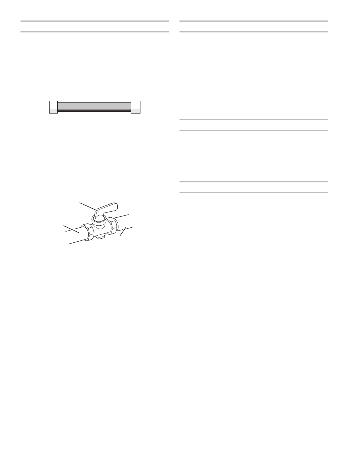
■ Must include a shut-off valve:
Install a manual gas line shut-off valve in an easily accessible
location. Do not block access to shut-off valve. The valve is
for turning on or shutting off gas to the cooktop.
B
A
C
A. Gas supply line
B. Shut-off valve open position
C. To cooktop
The gas pressure regulator supplied with this cooktop must be
used. The inlet pressure to the regulator should be as follows for
proper operation:
Natural Gas:
Minimum pressure: 6” (15.2 cm) WCP
Maximum pressure: 14” (35.5 cm) WCP
Propane Gas:
Minimum pressure: 11” (27.9 cm) WCP
Maximum pressure: 14” (35.5 cm) WCP
Contact local gas supplier if you are not sure about the inlet
pressure.
NOTE: For multi-unit installations, each unit must have its own
regulator (supplied with the unit).
Burner Input Requirements
Input ratings shown on the model/serial/rating plate are for
elevations up to 2,000 ft (609.6 m).
For elevations above 2,000 ft (609.6 m), ratings are reduced at
a rate of 4% for each 1,000 ft (304.8 m) above sea level (not
applicable for Canada).
For elevations above 6,560 ft (1999.5 m), a high altitude kit
is needed to avoid any reduced power output. See separate
Propane gas conversion instructions sheet.
Gas Supply Pressure Testing
Line pressure testing above 1/2 psi (3.5 kPa) gauge
[14” (35.6 cm) WCP]
The appliance and its individual shut-off valve must be
disconnected from the gas supply piping system during any
pressure testing of that system at test pressures in excess of
1/2psi (3.5 kPa).
Line pressure testing at 1/2 psi (3.5 kPa) gauge
[14” (35.6 cm) WCP] or lower
The appliance must be isolated from the gas supply piping
system by closing its individual manual shut-off valve during
any pressure testing of the gas supply piping system at test
pressures equal to or less than 1/2 psi (3.5 kPa).
†®TEFLON is a registered trademark of Chemours.
6
 Loading...