

Page 1
30" (76.2 CM) AND 36" (91.4 CM) GAS BUILT-IN
IMPORTANT:
Installer:
Homeo
IMPOR
Installateur
Pr
.
COOKTOP INSTALLATION INSTRUCTIONS
INSTRUCTIONS D’INSTALLATION DE LA
TABLE DE CUISSON À GAZ ENCASTRÉE
DE 30" (76,2 CM) ET DE 36" (91,4 CM)
Table of Contents/Table des matières
COOKTOP SAFETY ........................................................................1
INSTALLATION REQUIREMENTS .................................................3
Tools and Parts .............................................................................3
Location Requirements ................................................................3
Electrical Requirements ...............................................................4
Gas Supply Requirements ...........................................................5
INSTALLATION INSTRUCTIONS ...................................................6
Prepare Cooktop for Installation ..................................................6
Install Cooktop .............................................................................6
Make Gas Connection .................................................................7
Complete Installation ...................................................................8
WIRING DIAGRAM .........................................................................9
SÉCURITÉ DE LA TABLE DE CUISSON .....................................10
EXIGENCES D’INSTALLATION ...................................................11
Outillage et pièces ......................................................................11
Exigences d’emplacement .........................................................11
Spécifications électriques ..........................................................13
Spécifications de l’alimentation en gaz .....................................13
INSTRUCTIONS D’INSTALLATION .............................................15
Préparation de la table de cuisson pour l’installation................15
Installation de la table de cuisson ..............................................15
Raccordement au gaz ................................................................16
Achever l’installation ..................................................................17
SCHÉMA DE CÂBLAGE ...............................................................18
COOKTOP SAFETY
Your safety and the safety of others are very important.
We have provided many important safety messages in this manual and on your appliance. Always read and obey all safety
messages.
This is the safety alert symbol.
This symbol alerts you to potential hazards that can kill or hurt you and others.
All safety messages will follow the safety alert symbol and either the word “DANGER” or “WARNING.”
These words mean:
You can be killed or seriously injured if you don't immediately
DANGER
follow instructions.
All safety messages will tell you what the potential hazard is, tell you how to reduce the chance of injury, and tell you what can
happen if the instructions are not followed.
opriétaire : Conserver les instructions d'installation pour référence ultérieure
W10821219A
WARNING
Leave installation instructions with the homeowner.
wner: Keep installation instructions for future reference.
TANT :
: Remettre les instructions d'installation au propriétaire.
You
can be killed or seriously injured if you don't
instructions.
follow
Page 2
WARNING: Gas leaks cannot always be detected by smell.
Gas suppliers recommend that you use a gas detector approved by UL or CSA.
For more information, contact your gas supplier.
If a gas leak is detected, follow the “What to do if you smell gas” instructions.
IMPORTANT: Do not install a ventilation system that blows air downward toward this gas cooking appliance. This type of
ventilation system may cause ignition and combustion problems with this gas cooking appliance resulting in personal injury or
unintended operation.
WARNING: If the information in this manual is not followed exactly, a fire or explosion
may result causing property damage, personal injury or death.
– Do not store or use gasoline or other flammable vapors and liquids in the vicinity of this
or any other appliance.
– WHAT TO DO IF YOU SMELL GAS:
Do not try to light any appliance.
•
Do not touch any electrical switch.
•
Do not use any phone in your building.
•
Immediately call your gas supplier from a neighbor's phone. Follow the gas supplier's
•
instructions.
If you cannot reach your gas supplier, call the fire department.
•
– Installation and service must be performed by a qualified installer, service agency or
the gas supplier.
In the State of Massachusetts, the following installation instructions apply:
■ Installations and repairs must be performed by a qualified or licensed contractor, plumber, or gasfitter qualified or licensed by
the State of Massachusetts.
■ If using a ball valve, it shall be a T-handle type.
■ A flexible gas connector, when used, must not exceed 3 feet.
2
Page 3
INSTALLATION REQUIREMENTS
C
C
A
B
Tools and Parts
Gather the required tools and parts before starting installation.
Tools needed
■ Tape measure
■ Flat-blade screwdriver
15
■
⁄16" (24 mm) combination
wrench
■ Pipe wrench
■ Channel lock pliers
Parts supplied
■ Gas pressure regulator
■ Burner grates: common (4), center (1)
■ Burner bases (5)
■ Burner caps (5)
■ Simmer cap
■ Clamp brackets (2)
2
■ 2¹⁄
" (6.4 cm) clamping screws (2)
■ Foam tape seal
■ LP conversion kit - W10686634
Parts needed
Check local codes and consult gas supplier. Check existing gas
supply and electrical supply. See “Electrical Requirements” and
“Gas Supply Requirements” sections.
■ Marker or pencil
■ Pipe-joint compound
resistant to LP gas
■ Noncorrosive leak-detection
solution
IMPORTANT: To avoid damage to your cabinets, check with
your builder or cabinet supplier to make sure that the materials
used will not discolor, delaminate or sustain other damage.
Mobile Home - Additional Installation Requirements
The installation of this cooktop must conform to the
Manufactured Home Construction and Safety Standard, Title 24
CFR, Part 3280 (formerly the Federal Standard for Mobile Home
Construction and Safety, Title 24, HUD Part 280). When such
standard is not applicable, use the Standard for Manufactured
Home Installations, ANSI A225.1/NFPA 501A or with local codes.
In Canada, the installation of this cooktop must conform with the
current standards CAN/CSA-A240-latest edition, or with local
codes.
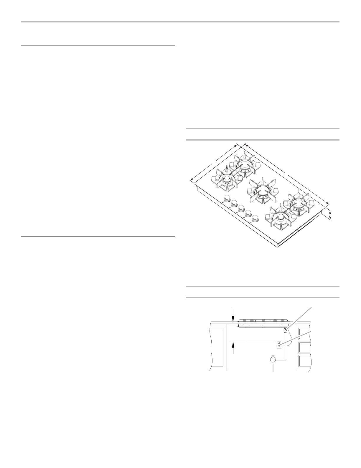
Product Dimensions
A
B
Location Requirements
IMPORTANT: Observe all governing codes and ordinances. Do
not obstruct flow of combustion and ventilation air.
■ It is the installer’s responsibility to comply with installation
clearances specified on the model/serial/rating plate. The
model/serial/rating plate is located on the underside of the
cooktop burner box.
■ Do not unpack the burner grates and bases until after the
cooktop is installed to avoid scratching the cooktop.
■ To eliminate the risk of burns or fire by reaching over heated
surface units, cabinet storage space located above the
surface units should be avoided. If cabinet storage is to be
provided, the risk can be reduced by installing a range hood
that projects horizontally a minimum of 5" (12.7 cm) beyond
the bottom of the cabinets.
■ The cooktop should be installed in a location away from
strong draft areas, such as windows, doors and strong
heating vents or fans.
■ All openings in the wall or floor where cooktop is to be
installed must be sealed.
■ Cabinet opening dimensions that are shown must be used.
Given dimensions are minimum clearances.
■ Grounded electrical supply is required. See “Electrical
Requirements” section.
■ Proper gas supply connection must be available. See “Gas
Supply Requirements” section.
■ The gas and electric supply should be located as shown in
“Gas and Electric Connection Locations” in the “Location
Requirements” section so that they are accessible without
requiring removal of the cooktop.
A. *21" (53.3 cm)
B. *30" (76.2 cm) on 30" (76.2 cm) models
36" (91.4 cm) on 36" (91.4 cm) models
C. 31/4" (8.3 cm)
*Metal tabs should not be bent during installation
Gas and Electric Connection Locations
D
A. Gas pressure regulator (supplied) - arrow pointed
toward cooktop
B. 3 prong grounding type outlet with correct polarity
C. Gas shutoff valve
D. 18" (45.7 cm) minimum
3
Page 4

Installation Clearances
A
D
H
IMPORTANT: If installing a range hood or microwave hood
combination above the range, follow the range hood or
microwave hood combination installation instructions for
dimensional clearances above the cooktop surface.
B
Electrical Requirements
WARNING
C
F
J
I
E
G
A. 18" (45.7 cm) minimum clearance upper cabinet to countertop
B. Cabinet
C. 36" (91.4 cm)
D. 13" (33 cm) maximum recommended upper cabinet depth
E. 6" (15.2 cm) minimum side wall clearance
F. 30" (76.2 cm) minimum clearance between top of cooktop
platform and bottom of uncovered wood or metal cabinet
(24" [61 cm] minimum clearance if bottom of wood or metal
cabinet is covered by not less than ¹⁄4" [0.6 cm] flame retardant
millboard covered with not less than No. 28 MSG sheet steel,
0.015" [0.04 cm] stainless steel, or 0.024" [0.06 cm] aluminum
or 0.020" [0.05 cm] copper)
G. 25⁄16" (5.9 cm) minimum distance to rear combustible surface
H. 25⁄16" (5.9 cm) minimum distance to front countertop edge
I. Cutout width - 29³⁄8" (74.6 cm) on 30" (76.2 cm) models
Cutout width - 35³⁄8" (89.9 cm) on 36" (91.4 cm) models
J. Cutout depth - 20³⁄8" (51.8 cm)
NOTE: After making the countertop cutout, some installations
may require notching down the base cabinet side walls to clear
the burner box. To avoid this modification, use a base cabinet
with sidewalls wider than the cutout.
If cabinet has a drawer, a 4" (10.2 cm) depth clearance from the
countertop to the top of the drawer (or other obstruction) in base
cabinet is required. The drawer depth may need to be shortened
to avoid interfering with the regulator and power cord.
Electrical Shock Hazard
Plug into a grounded 3 prong outlet.
Do not remove ground prong.
Do not use an adapter.
Do not use an extension cord.
Failure to follow these instructions can result in death,
fire, or electrical shock.
IMPORTANT: The cooktop must be electrically grounded in
accordance with local codes and ordinances, or in the absence
of local codes, with the National Electrical Code, ANSI/NFPA 70
or Canadian Electrical Code, CSA C22.1.
This cooktop is equipped with an electronic ignition system
that will not operate if plugged into an outlet that is not properly
polarized.
This cooktop is equipped with an electronic ignition system that
will not operate properly if plugged into a ground fault interrupt
circuit.
If codes permit and a separate ground wire is used, it is
recommended that a qualified electrical installer determine
that the ground path is adequate.
A copy of the above code standards can be obtained from:
National Fire Protection Association
1 Batterymarch Park
Quincy, MA 02169-7471
CSA International
8501 East Pleasant Valley Road
Cleveland, OH 44131-5575
■ A 120-volt, 60 Hz., AC only, 15-amp fused, electrical circuit
is required. A time-delay fuse or circuit breaker is also
recommended. It is recommended that a separate circuit
serving only this range be provided.
■ Electronic ignition systems operate within wide voltage limits,
but proper grounding and polarity are necessary. Check that
the outlet provides 120-volt power and is correctly grounded
and polarized.
■ The wiring diagram is provided with this cooktop. See
“Wiring Diagram” section.
4
Page 5

Gas Supply Requirements
A
C
WARNING
Explosion Hazard
Use a new CSA International approved gas supply line.
Install a shut-off valve.
Securely tighten all gas connections.
If connected to LP, have a qualified person make sure
gas pressure does not exceed 14" (36 cm) water
column.
Examples of a qualified person include:
licensed heating personnel,
authorized gas company personnel, and
authorized service personnel.
Failure to do so can result in death, explosion, or fire.
Observe all governing codes and ordinances.
IMPORTANT: This installation must conform with all local codes
and ordinances. In the absence of local codes, installation must
conform with American National Standard, National Fuel Gas
Code ANSI Z223.1 - latest edition or CAN/CGA B149 - latest
edition.
IMPORTANT: Leak testing of the range must be conducted
according to the manufacturer’s instructions.
Gas Supply Line
■ Provide a gas supply line of ¾" (1.9 cm) rigid pipe to the
cooktop location. A smaller size pipe on longer runs may
result in insufficient gas supply. Pipe-joint compounds
that resist the action of LP gas must be used. Do not use
TEFLON®† tape. With LP gas, piping or tubing size can be ½"
minimum. Usually, LP gas suppliers determine the size and
materials used in the system.
Flexible metal appliance connector:
■ If local codes permit, use a
tubing gas connector, designed by CSA to connect the
cooktop to the rigid gas supply line.
■ A ½" (1.3 cm) male pipe thread is needed for connection
to the female pipe threads of the inlet to the appliance
pressure regulator.
■ Do not kink or damage the flexible metal tubing when
moving the cooktop.
■ Must include a shutoff valve:
The supply line must be equipped with a manual shutoff
valve. This valve should be located in the same room but
external to the cooktop opening, such as an adjacent
cabinet. It should be in a location that allows ease of
opening and closing. Do not block access to shutoff
valve. The valve is for turning on or shutting off gas to the
cooktop.
5
⁄8" flexible stainless steel
B
Type of Gas
Natural Gas:
■ This cooktop is factory-set for use with Natural gas. To
convert to LP gas, see the Gas Conversion instructions
provided in the package containing the literature. The model/
serial/rating plate located on the underside of the burner box
has information on the types of gas that can be used. If the
types of gas listed do not include the type of gas available,
check with the local gas supplier.
LP Gas conversion:
Conversion must be done by a qualified service technician.
No attempt shall be made to convert the appliance from the gas
specified on the model/serial/rating plate for use with a different
gas without consulting the serving gas supplier. See the Gas
Conversion instructions provided in the package containing the
literature.
A. Gas supply line
B. Shutoff valve “open” position
C. To cooktop
Gas Pressure Regulator
The gas pressure regulator supplied with this cooktop must be
used. The inlet pressure to the regulator should be as follows for
proper operation:
Natural Gas:
Minimum pressure: 6" (15.2 cm) WCP
Maximum pressure: 14" (35.5 cm) WCP
LP Gas:
Minimum pressure: 11" (27.9 cm) WCP
Maximum pressure: 14" (35.5 cm) WCP
Contact local gas supplier if you are not sure about the
inlet pressure.
†®TEFLON is a registered trademark of E.I. Du Pont De Nemours and Company.
5
Page 6

Burner Input Requirements
WARNING
A
B
C
E
Gas Supply Pressure Testing
Input ratings shown on the model/serial/rating plate are for
elevations up to 2,000 ft (609.6 m).
For elevations above 2,000 ft (609.6 m), ratings are reduced at
a rate of 4% for each 1,000 ft (304.8 m) above sea level (not
applicable for Canada).
For elevations above 6,560 ft (1999.5 m) a high altitude kit is
needed to avoid any reduced power output. See separate LP
gas conversion instructions sheet.
INSTALLATION INSTRUCTIONS
Prepare Cooktop for Installation
Excessive Weight Hazard
Use two or more people to move and install cooktop.
Failure to do so can result in back or other injury.
Write down the model and serial numbers before installing the
cooktop. Both numbers are located on the center underside of
the burner box.
Unpack the parts supplied with your cooktop. Do not unpack
or remove the grates and burner bases from the carton until
after the cooktop is installed to reduce the risk of scratching the
cooktop.
The parts shipped with the cooktop depend on the model
ordered. See the “Tools and Parts” section for a complete list of
parts supplied with the cooktop.
Decide on the final location for the cooktop. Locate existing
wiring to avoid drilling into or severing wiring during installation.
The pressure regulator and flexible stainless steel gas supply line
can be assembled to the cooktop before or after the cooktop is
installed. See the “Make Gas Connection” section.
1. (Optional) Remove the foam strip from the hardware
package. Remove the backing from the foam strip. Apply the
foam strip with the adhesive side to the countertop on of the
edge of the cutout, front, back and sides.
NOTE: The foam strip helps keep the underside of the
cooktop frame free from debris and helps the cooktop sit flat
on uneven countertops.
Line pressure testing above ½ psi gauge (14" WCP)
The appliance and its individual shutoff valve must be
disconnected from the gas supply piping system during any
pressure testing of that system at test pressures in excess of
½ psi (3.5 kPa).
Line pressure testing at ½ psi gauge (14" WCP) or lower
The appliance must be isolated from the gas supply piping
system by closing its individual manual shutoff valve during
any pressure testing of the gas supply piping system at test
pressures equal to or less than ½ psi (3.5 kPa).
Install Cooktop
Install the pressure regulator to the cooktop before installing the
cooktop. See the “Make Gas Connections” section.
Cooktop over built-in oven
IMPORTANT: Clamping brackets should not be used.
1. Install the cooktop into the countertop cutout by tilting one
end of the cooktop into the cutout, then lowering the other
end into the cutout.
NOTE: Make sure that the front edge of the cooktop is
parallel to the front edge of the countertop. If repositioning
is needed, lift the entire cooktop up to avoid scratching the
countertop.
Install cooktop into countertop
1. Remove the 2 hold-down screws located in each side of the
cooktop burner box.
2. Attach the 2 hold-down brackets to the burner box.
3. Install the mounted cooktop bracket into the countertop
cutout by tilting one end of the cooktop into the cutout.
Shift the cooktop to the side of the cutout the bracket was
lowered into. Lower the other end into the cutout so the
bracket clears the underside of the countertop. Center the
cooktop in the opening, then completely lower the cooktop
into the cutout.
4. Start the hold-down screws into the hold-down brackets.
A
B
C
D
A. Countertop
B. Wood block
5. Center the cooktop in the opening and, using a wood block
A. Countertop
B. Foam strip
6
C. Cutout
between the screw and the countertop, moderately tighten
the screws to secure cooktop.
IMPORTANT: Do not tighten screws directly against the
countertop.
C. Hold-down screw
D. Hold-down bracket
E. Burner box
Page 7

Make Gas Connection
E
A
B
D
WARNING
Explosion Hazard
Use a new CSA International approved gas supply line.
Install a shut-off valve.
Securely tighten all gas connections.
If connected to LP, have a qualified person make sure
gas pressure does not exceed 14" (36 cm) water
column.
Examples of a qualified person include:
licensed heating personnel,
authorized gas company personnel, and
authorized service personnel.
Failure to do so can result in death, explosion, or fire.
IMPORTANT: All connections must be wrench-tightened. Do
not make connections to the gas regulator too tight. Making
the connections too tight may crack the regulator and cause
a gas leak. Do not allow the regulator to turn on the pipe when
tightening fittings.
Use only pipe-joint compound made for use with Natural and
LP gas.
Do not use TEFLON® tape. You will need to determine the fittings
required depending on your installation.
Typical flexible connection
1. Apply pipe-joint compound made for use with LP gas to the
larger thread ends of the flexible connector adapters (see D
and F in the following illustration).
2. Attach 1 adapter to the gas pressure regulator and the other
adapter to the gas shutoff valve. Tighten both adapters.
3. Use a 15⁄16" combination wrench and channel lock pliers to
attach the flexible connector to the adapters. Check that
connector is not kinked.
No appliance/obstructions
below cooktop
Suggested installation to
avoid interference below
cooktop
To Assemble Pressure Regulator:
1. Connect the flexible stainless steel connector to the pressure
regulator using a ¹⁄2" male pipe thread adapter.
A combination of pipe fittings must be used to connect the
cooktop to the existing gas line. Shown in the following
illustration is a typical connection. Your connection may be
different, according to the supply line type, size and location.
A
B
C
D
A
B
C
D
NOTE: When installing the cooktop above a built-in oven,
install a 90º elbow - ¹⁄2" female to ¹⁄2" male between the
cooktop manifold pipe and the pressure regulator. The
regulator must be set with the arrow pointing toward the
cooktop. Apply pipe joint compound for use with LP gas to
the end of the cooktop manifold pipe and the male end of
the 90° elbow.
2. Install the pressure regulator with the arrow pointing up
toward the bottom of the burner box and in a position where
you can reach the regulator.
E
F
G
F
G
H
I
H
J
I
A. Manifold entrance
B. Gas pressure regulator
C. Use pipe-joint compound.
D. Adapter (must have 1/2" male
C
A. Gas pressure regulator
B. Up arrow - regulator must be installed
with arrow pointing up at cooktop bottom.
C. Adapter - must have 1/2" male pipe thread
D. UL listed or CSA approved flexible
stainless steel gas supply line
pipe thread)
E. Flexible connector
F. Adapter
G. Use pipe-joint compound.
H. Manual gas shutoff valve
I. 1/2" or 3/4" gas pipe
K
A. Manifold entrance
B. 3/8" elbow
C. Use pipe-joint compound.
D. Adapter (must have 3/8" male
pipe thread)
E. Flexible connector (pass
through wall between cabinets)
F. Adapter (must have 3/8" male
pipe thread)
G. Use pipe-joint compound.
H. Appliance pressure regulator
(supplied)
I. 1/2" or 3/4" gas pipe
J. Manual gas shutoff valve
K. 1/2" or 3/4" gas pipe
7
Page 8

C
B
C
A
B
B
Complete Connection
A
B
1. Open the manual shutoff valve in the gas supply line. The
valve is open when the handle is parallel to the gas pipe.
WARNING
A. Closed valve
B. Open valve
2. Test all connections by brushing on an approved
noncorrosive leak-detection solution. If bubbles appear, a
leak is indicated. Correct any leak found.
3. Install all burner caps and burner bases.
A
B
Standard Burner
A. Cap
B. Spreader
C. Electrode
A
Dual Flame Burner
A. Cap
B. Spreader
C. Electrode
Burner installation:
To install the burner base, insert the igniter electrode into the
burner base hole.
Install surface grates:
Each burner has a locating ridge on the cooktop surface that
mates with the bottom of the surface grate. To install the burner
grate; align the recess in the burner grate with the locating ridge
on the cooktop. Evenly and gently lower the burner grate onto
the cooktop surface. Ensure the four rubber feet of the surface
grate are contacting the cooktop surface. If all four feet are not
touching, remove the surface grate and ensure that the mating
surfaces are debris-free. Reinstall burner grate.
NOTE: On 36" (91.4 cm) models; the center surface grate is
different than the left and right grates.
Electrical Shock Hazard
Plug into a grounded 3 prong outlet.
Do not remove ground prong.
Do not use an adapter.
Do not use an extension cord.
Failure to follow these instructions can result in death,
fire, or electrical shock.
4. Plug into a grounded 3 prong outlet.
Complete Installation
Electronic Ignition System
Check Operation of Surface Burners
1. Push in and turn the surface burner control knobs to the
HI position.
The surface burner flame should light within 4 seconds. The
first time a surface burner is lit, it may take longer than 4
seconds to light because of air in the gas line.
2. Check the flame on HI for a blue color. It should be clean
and soft in character. No yellow tip, blowing or lifting of flame
should occur. Occasional orange flashes are normal and
reflect different elements in the air or gas.
3. Repeat for the LO position.
4. Repeat for the SIM position.
5. After verifying the proper burner operation, turn the control
knobs to OFF.
If burners do not light properly:
■ Turn the surface burner control knob to the OFF position.
■ Check that the power supply cord is plugged in and the
circuit breaker has not tripped or the fuse blown.
■ Check that the gas shutoff valve is set to the “open” position.
■ Check that the burner bases and caps are properly
positioned on the burners.
A. Correct
B. Incorrect
Recheck the operation of the surface burners. If a burner does
not light at this point, call 1-800-JENN-AIR (536-6247).
8
Page 9

30" (76.2 cm) and 36" (91.4 cm) Cooktops
120 VAC, 60 Hz, 1 Phase, 15 Amp
GND
Switches
WIRING DIAGRAM
Power Cord
Plug
L1
N
GN
GND
BK
WH
RF
RR
BK
WH #1
BK
N
L1
WH #2WH #3
N
L1
RR RF
C
Electrodes
LR
LF
C
N
L1
LR
N
L1
LF
N
L1
Spark Modules
WH #4WH #5
BK
BK
BK
BK
RF
BK
BK
RR
BK
C
BK
LR
BK
LF
Valve
NOTE: Electric circuit is closed when knob is pushed in and rotated from 0° to 210° counterclockwise from OFF.
9
Page 10

W10821219A
®
/™ ©2015 Jenn-Air. Used under license in Canada. All rights reserved.
Utilisé sous licence au Canada. Tous droits réservés.
10/15
 Loading...