

Jenn-Air JGC1430, JGC1536 User Manual
INSTALLATION
SEALED GAS COOKTOPS
MANUAL
Models: JGC1430 & JGC1536
403 WEST FOURTH STREET, NORTH • NEWTON, IA 50208
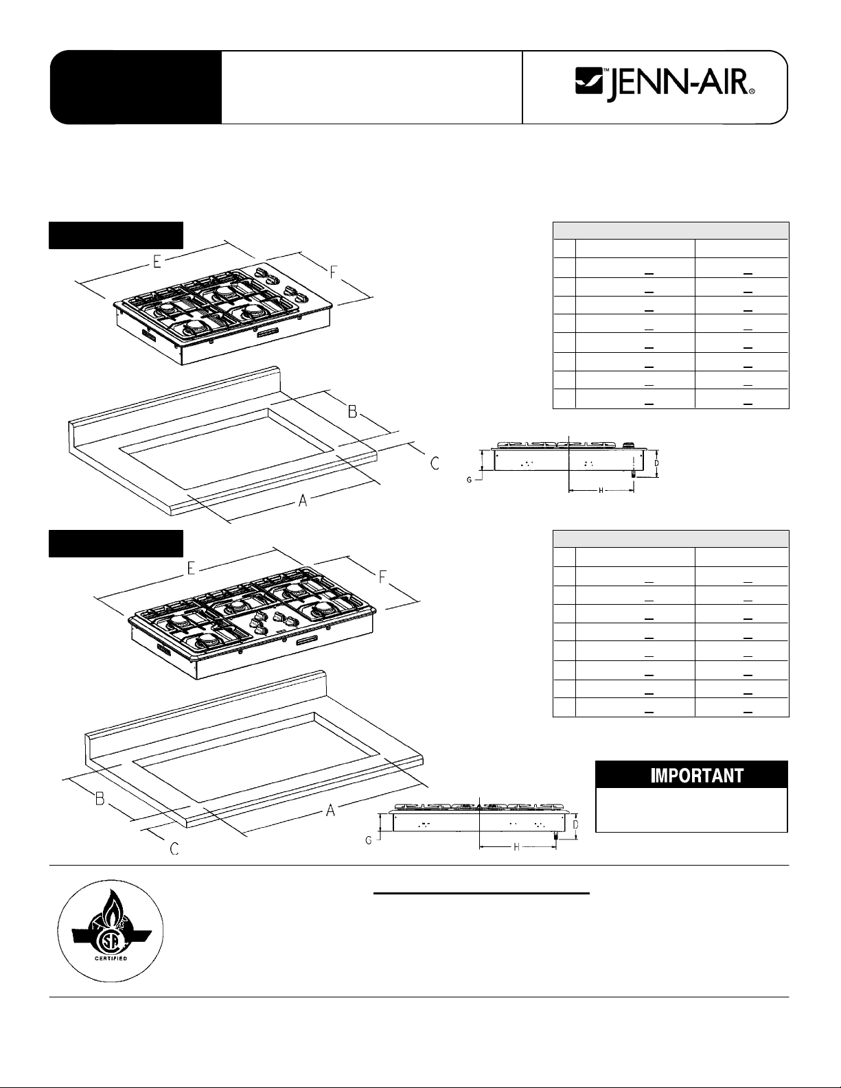
IMPORTANT: Dimensions Shown in Both Inches and Centimeters.‘
IMPORTANT:
underside of burner box for this information. Do not attempt to convert this appliance for use with a gas other than the type
specified.
30″ MODEL
Be sure the appliance being installed is equipped for the gas to be supplied. Refer to serial plate on
DIMENSIONS
inches cm
A281/2 +
B 19 15/16 +
C21/8 +
D51/4 +
E291/2 +
F211/2 +
G 3 13/16 +
H121/4 +
1/16 72.4 + 0.2
1/16 50.6 + 0.2
1/16 5.4 + 0.2
1/16 13.3 + 0.2
1/16 74.9 + 0.2
1/16 54.6 + 0.2
1/16 9.7 + 0.2
1/16 31.1 + 0.2
36″ MODEL
DIMENSIONS
inches cm
A341/2 +
B 19 15/16 +
C21/8 +
D51/4 +
E36 +
F21 +
G 3 13/16 +
H151/4 +
1/16 87.6 + 0.2
1/16 50.6 + 0.2
1/16 5.4 + 0.2
1/16 13.3 + 0.2
1/16 91.4 + 0.2
1/16 53.3 + 0.2
1/16 9.7 + 0.2
1/16 38.7 + 0.2
CUTOUT DIMENSIONS
ARE CRITICAL
SPECIAL WARNING:
IMPROPER INSTALLATION, ADJUSTMENT, ALTERATION, SERVICE, MAINTENANCE
OR USE OF RANGE CAN RESULT IN SERIOUS INJURY OR PROPERTY DAMAGE.
NOTICE TO INSTALLER: Leave these instructions with the appliance.
NOTICE TO CONSUMER: Retain these instructions for future reference.
8101P736--60
(10-06-00)
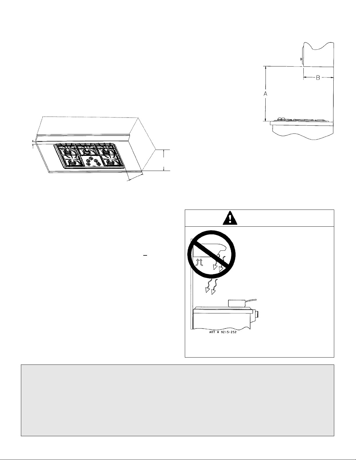
Location Of Your Jenn--Air Appliance
Locate this appliance away from combustible materials
such as window curtains and combustible wall
decorations.
Minimum horizontal clearance between the edge of the
appliance and combustible construction extending from
the cooking surface to 18″ (45.72 cm) above the cooking
surface is:
1.0″ (2.54 cm) at rear
6″ (15.24 cm) at sides
(Dimensions apply to both 30″ and 36″ wide models).
1.0″
2.54 cm
6″
15.24 cm
FIGURE 1
18″
45.72 cm
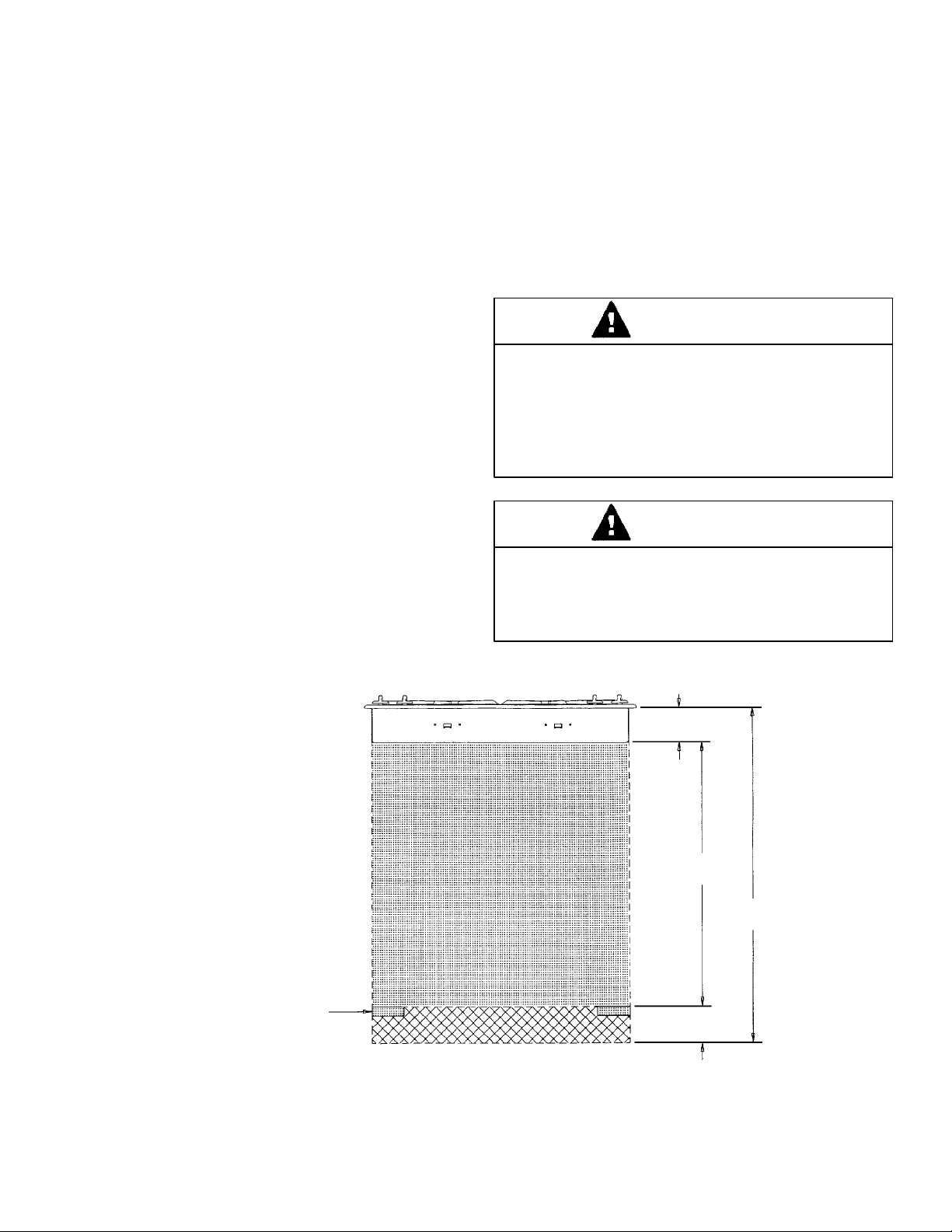
Installing Cabinetry Over Your
Jenn--Air Cooktop
A=30″ (76.2 cm) minimum
vertical clearance
between cooking surface
and construction above
the appliance. This
clearance may be
reduced to not less than
24 inches (60.96 cm) by
protecting the underside
of the combustible
material or metal cabinet
above the cooking
surface with not less than
1/4 inch (.635 cm)
insulating millboard
covered with sheet metal
not less than 0.0122 inch
thick.
B=13″ (33.02 cm) maximum depth of cabinets installed
above cooktop.
Avoid use of cabinets above cooktop for storage space to
eliminate associated potential hazards such as reaching
over open flames.
FIGURE 2
Preparation Of Countertop
The countertop cutout must be prepared according to the
illustration on page 1 of these instructions.
CAUTION: Cutout dimensions are critical. Dimensions
must be measured and cut accurately to within +
(.159 cm) to ensure proper fit.
1/16″
Important Preparation Suggestions
1. Chamfer all exposed edges of decorative laminate to
prevent damage from chipping.
2. Radius corners of cutout and file to insure smooth
edges and prevent corner cracking. Recommend
1/4″ or 3/8″ diameter drill in each corner.
3. Rough edges, inside corners which have not been
rounded and forced fits can contribute to cracking of
the countertop laminate.
4. Countertop must be supported within 3″ (7.62 cm) of
cutout.
NOTE: THE FIGURE MAY NOT ACCURATELY REPRESENT
YOUR RANGE OR COOKTOP; HOWEVER, THIS WARNING
APPLIES TO ALL GAS COOKIN G PRODUCTS.
WARNING
THIS PRODUCT SHOULD NOT
BE INSTALLED BELOW A
VENTILATION TYPE HOOD
SYSTEM THAT DIRECTS AIR
IN A DOWNWARD DIRECTION.
(SEE FIGURE)
THESE SYSTEMS MAY CAUSE
IGNITION AND COMBUSTION
PROBLEMS WITH THE GAS
BURNERS RESULTING IN
PERSONAL INJURY AND MAY
AFFECT THE COOKING
PERFORMANCE OF THE UNIT.
Required Adjustments At Time Of Installation
The installation of this appliance must conform with local codes, or in the absence of local codes, with the latest edition
of the National Fuel Gas Code ANSI Z223.1 USA or current CAN/CGA-B149 INSTALLA TION CODE.
V This appliance was manufactured for use with Natural Gas. If LP gas is the fuel of choice, follow the conversion to
LP procedure found in the installation instructions.
V Test all external connections for gas leaks. Never test for gas leaks with an open flame.
V Test all electrical connections.
2
Check the cooktop serial plate to see if the cooktop is
approved for installation in mobile homes and/or
recreational park trailers. Serial plate is located on the
bottom of the unit.
All supply piping, except as noted, should use common
National Pipe Thread (N.P.T.). For all pipe connections
use an approved pipe joint compound resistant to the
action of LP gas.
If approved, the following items are applicable:
Mobile Homes
The installation of a range designed for mobile home
installation must conform with the Manufactured Home
Construction and Safety Standard, Title 24 CFR, Part
3280 [formerly the Federal Standard for Mobile Home
Construction and Safety, Title 24 HUD, (Part 280)] or,
when such standard is not applicable, the Standard for
Manufactured Home Installations, ANSI A225.1/NFP A
501A, or with local codes.
In Canada the range must be installed in accordance with
the current CSA Standard C22.1 -- Canadian Electrical
Code Part 1 and Section Z240.4.1 -- Installation
Requirements for Gas Burning Appliances in Mobile
Homes (CSA Standard CAN/CSA -- Z240MH).
Recreational Park Trailers
The installation of a range designed for recreational park
trailers must conform with state or other codes or, in the
absence of such codes, with the Standard for
Recreational Park Trailers, ANSI A119.5-latest edition.
In Canada the range must be installed in accordance with
CAN/CSA -- Z240.6.2 -- Electrical Requirements for R.V.’s
(CSA Standard CAN/CSA -- Z240 RV Series) and Section
Z240.4.2 -- Installation Requirements for Propane
Appliances and Equipment in R.V.’s (CSA Standard
CAN/CSA -- Z240 RV Series).
Installation Of Appliance
The installation of this appliance must conform with local
codes or, in the absence of local codes, with the National
Fuel Gas Code, ANSI Z223.1--Latest Edition, or, in
Canada, CAN/CGA-B149 Installation Code, Latest
Edition.
This appliance, when installed, must be electrically
grounded in accordance with local codes or, in the
absence of local codes, with the National Electrical Code
ANSI/NFP A No. 70--Latest Edition, or, in Canada, current
CSA Standard C22.1 Canadian Electrical Code, Part 1.
In Th e Commonwealth Of Massachusetts
This product must be installed by a licensed plumber or
gas fitter when installed within the Commonwealth of
Massachusetts.
A “T” handle type manual gas valve must be installed in
the gas supply line to this appliance.
CAUTION: Warranty is void on Jenn--Air equipment
installed other than as recommended by manufacturer.
This appliance is designed for use with the appliance gas
pressure regulator supplied with this appliance. It must be
installed in the gas line ahead of the gas manifold
entrance. It is preset for use with natural gas and must be
converted, as described on pages 8 and 9, for use with
LP gas. (See figures 7 -- 12).
This appliance is designed to operate at a pressure of 5
inches of water column (36″ models), 4 inches of water
column (30″ models) on natural gas or, if converted for
use with LP gas (propane or butane), 10 inches water
column. Make sure this appliance is supplied with and
adjusted for the type of gas for which it is designed.
This appliance was adjusted at the factory for use with
natural gas. If, at any time, this appliance is to be used
with a different type of gas, all of the conversion
adjustments described on pages 8 and 9 must be made
by a qualified service technician before attempting to
operate the cooktop on that gas. Natural gas should be
supplied to the appliance pressure regulator at a line
pressure between 6 and 14 inches of water column or, if
converted for LP gas, between 11 and 14 inches.
WARNING
If the line pressure supplying the appliance pressure
regulator exceeds 14″ water column (any gas), an
external regulator must be installed in the gas line ahead
of the appliance regulator to reduce the pressure to no
more than 14″ water column. Failure to do this can result
in malfunction and damage to the appliance.
Insure this appliance is adjusted for the type of gas
supplied to it and that the gas supply pressure to the
appliance regulator is within the proper pressure range.
S If no other appliance is to be installed in the cabinetry
below this unit, proceed as instructed under paragraph
1, page 4.
S If this unit is to be installed over a Jenn--Air Model
JJW9530, JJW9130, JJW8530 or JJW8130 Series
Electric Wall Oven proceed as instructed under
paragraph 2, page 5.
NOTE: In Canada, gas utilization codes prohibit use of
street elbows. Use standard pipe elbows and make
modifications to these instructions as necessary.
A flexible gas connector, when used, must not exceed a
length of three (3) feet / 36 inches.
3
Connecting Appliance To Gas Supply
A QUALIFIED SERVICE TECHNICIAN OR GAS
APPLIANCE INSTALLER MUST MAKE THE GAS
SUPPLY CONNECTION. Leak testing of the
appliance shall be conducted by the installer
according to the instructions given.
Gas supply piping MUST conform to all local,
municipal and state building codes and local utility
regulations.
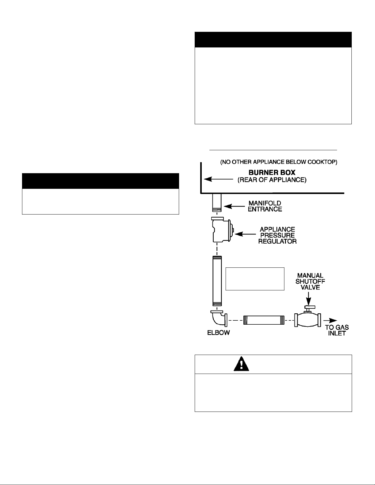
1. IF NO OTHER APPLIANCE IS TO BE INSTALLED
BELOW THIS COOKTOP
Join the appliance pressure regulator supplied with this
appliance to the entrance threads of the Gas Manifold.
The appliance regulator is marked with a directional
arrow indicating correct direction of gas flow. Ensure
the appliance regulator is installed with the arrow
pointing toward the gas manifold entrance. Tighten the
appliance regulator to 20 to 30 ft-lbs of torque.
IMPORTANT
Never tighten to more than 35 ft-lbs of torque. Always
use an approved pipe joint compound resistant to the
action of LP gas.
IMPORTANT
Apply a non-corrosive leak detection fluid to all jointsand
fittings in the gas connection between the supply line
shut-off valve and the cooktop. Include gas fittings and
joints in the cooktop if connections were disturbed
during installation. Check for leaks! Bubbles appearing
around fittings and connections will indicate a leak. If a
leak appears, turn off supply line gas shut-off valve,
tighten connections, turn on the supply line gas shut off
valve, and retest for leaks. Never test for gas leaks with
an open flame.
ILLUSTRATIVE GAS SUPPLY PIPING
(3/8″ N.P.T.)
Install the appliance in its counter cutout.
Make the gas connection to the inlet of the appliance
pressure regulator with 1/2″ NPT male pipe threads.
Install a manual shut-off valve in an accessible location in
the gas line ahead of the appliance pressure regulator
and external to this appliance for the purpose of turning
on or shutting off gas to the appliance.
Make additional pipe connections as necessary ahead of
the shut-off valve to the gas supply source. Assure all
pipe joint connections are gas tight.
ALL SUPPLY SIDE
PIPE JOINTS
1/2″ N.P.T.
FIGURE 3
WARNING
Gas leaks may occur in your system and result in a
dangerous situation. Gas leaks may not be detected by
smell alone. Gas suppliers recommend you purchase and
install an UL approved gas detector. Install and use in
accordance with the manufacturer’s instructions.
4
2. IF THIS UNIT WILL HAVE A JENN--AIR MODEL
WALL OVEN INSTALLED BELOW THIS COOKTOP.
NOTE 1: This appliance and its gas and electrical supply
sources must be installed before the wall oven is installed.
See illustration (Electrical Wiring Information -- page 7;
figure 6) for recommended electrical supply source
locations.
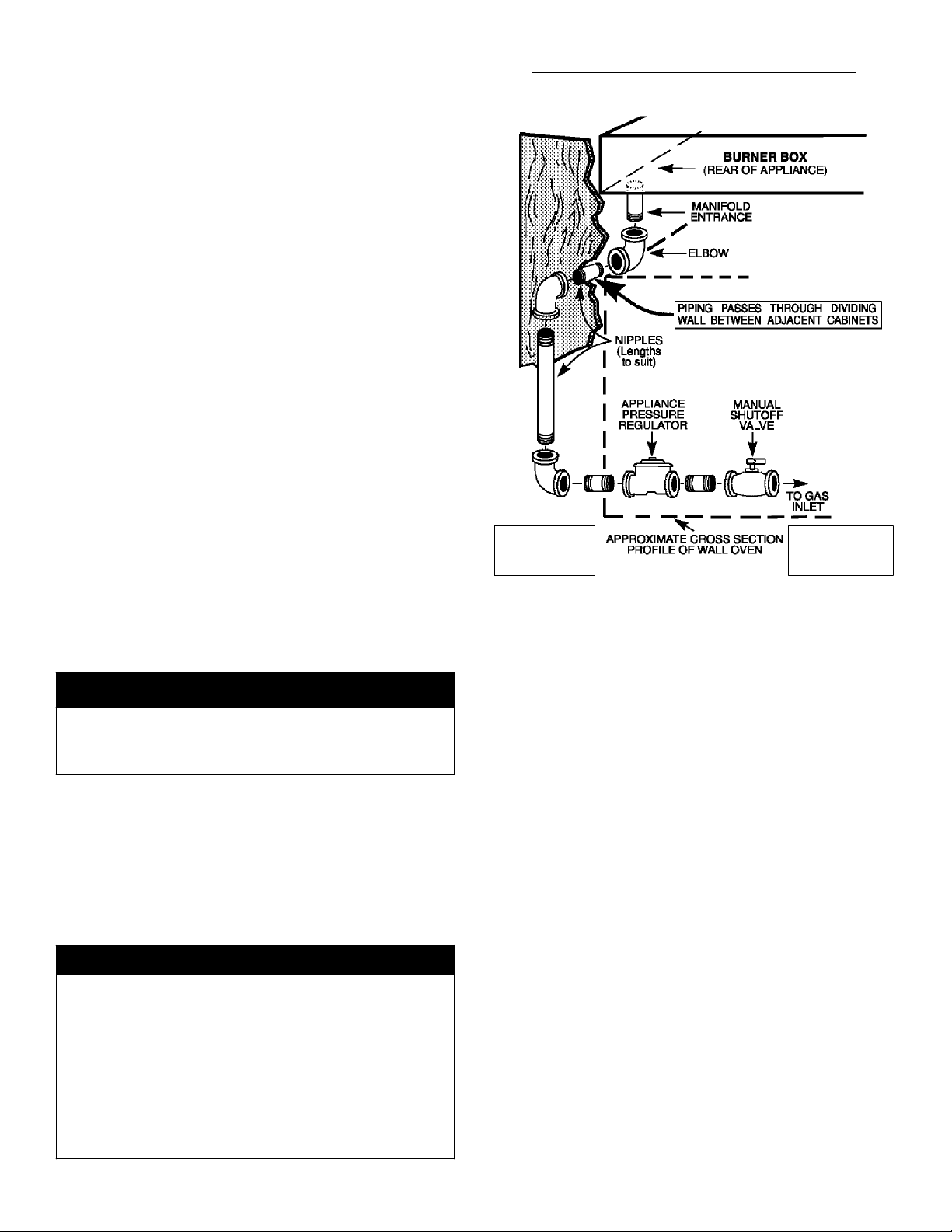
ILLUSTRATIVE GAS SUPPLY PIPING
(WALL OVEN INSTALLED BELOW 30″ COOKTOP)
NOTE 2: It may be necessary to extend gas supply piping
for this appliance into adjacent under-counter cabinetry
when a wall oven is installed below this appliance.
Joina3/8″ NPT pipe elbow (locally available) to the male
threads at the manifold entrance. When joined, ensure
open threads of the elbow face toward the right side of
the appliance. Install the appliance in its counter cutout.
Joina3/8″ NPT pipe nipple to the elbow using a pipe
section of sufficient length to extend, horizontally, beyond
the right side of the wall oven. (To accomplish this it may
be necessary to extend the pipe section into adjacent
cabinetry.) Join additional 3/8″ NPT elbow(s) and pipe
nipples, as necessary , to accomplish the following:
Join the outlet of the appliance pressure regulator
supplied with this appliance to the male threads of the
newly installed gas supply piping. Install the appliance
regulator in a location which will be accessible beside or
below the wall oven. Insure the appliance regulator is
installed with its directional arrow pointing in the direction
of gas flow. Tighten the appliance regulator to 20 to 30
ft-lbs of torque.
IMPORTANT
Never tighten to more than 35 ft-lbs of torque. Always
use an approved pipe joint compound resistant to the
action of LP gas.
(3/8″ N.P.T.)
ALL UNIT SIDE
PIPE JOINTS
3/8″ N.P.T.
FIGURE 4
ALL SUPPLY SIDE
PIPE JOINTS
1/2″ N.P.T.
Note, regarding Figure 4, above:
S For convenience in service a union (not shown: locally
available) should be included in the piping illustrated in
figure 4, in a location most practical for the installation.
Generally, a practical location is in the cabinet below
this appliance, near the manifold entrance, rather than
in an adjoining cabinet.
Locate and join a manual shut-off valve in an accessible
location in the gas line ahead of the appliance regulator
and external to the appliance for the purpose of turning on
or shutting off gas to the appliance.
Make additional pipe connections as necessary ahead of
the shut-off valve to the gas supply source. Assure all
pipe joint connections are gas tight.
IMPORTANT
Apply a non-corrosive leak detection fluid to all joints and
fittings in the gas connection between the supply line
shut-off valve and the cooktop. Include gas fittings and
joints in the cooktop if connections were disturbed during
installation. Check for leaks! Bubbles appearing around
fittings and connections will indicate a leak. If a leak
appears, turn off supply line gas shut-off valve, tighten
connections, turn on the supply line gas shut off valve,
and retest for leaks. Never test for gas leaks with an open
flame.
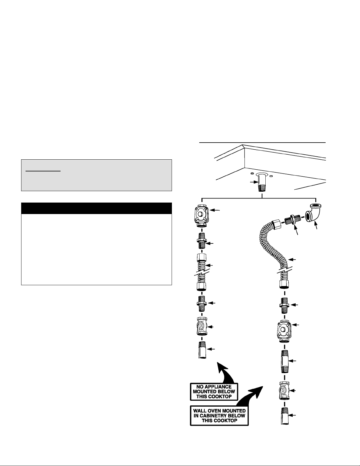
S If the alternative piping method shown in figure 5 is
selected for the installation, no union is required. (The
flexible appliance connector illustrated provides the
union joints necessary for servicing.) When a dividing
wall is present and a flexible connector is used, it is
recommended for convenience in both installation and
service, that the flexible connector pass through the
dividing wall. Any flexible connector used with this
appliance must satisfy all requirements stated in
the text accompanying figure 5.
5
Alternative Piping Methods T o
Connect Appliance To Gas Supply
A TRAINED SERVICE TECHNICIAN OR GAS
APPLIANCE INSTALLER MUST MAKE THE GAS
SUPPLY CONNECTION. Leak testing of the
appliance shall be conducted by the installer
according to the instructions given.
Unless prohibited by local codes or ordinances, a new
A.G.A. -- Certified, flexible metal appliance connector may
be used to connect this appliance to its gas supply. The
connector must be no more than 5 feet in length. Per
figure 5, use appropriate flare union adapter at each end
of the flexible connector. If a flexible connector is used
assure that both the appliance pressure regulator and
manual shut-off valve are joined solidly to other
permanent hard piping (either gas supply or the appliance
manifold) so as to be physically stationary. See
illustrations below.
CAUTION: Do not attempt to attach the flexible
connector directly to an external pipe thread.
Connection requires flare union adapters.
Pressure Testing
The appliance must be isolated from the gas supply
piping system by closing its individual manual shut-off
valve during any pressure testing of the gas supply piping
system at test pressures equal to or less than 1/2 pounds
per square inch (3.5 kPa).
This appliance, as well as its individual shut-off valve,
must be disconnected from the gas supply piping system
during any pressure testing of the system at test
pressures in excess of 1/2 pounds per square inch (3.5
kPa).
When checking appliance regulator function, make certain
pressure of natural gas supply is between 6 and 14
inches of water column or, if converted for LP gas,
between 11 and 14 inches of water column.
ILLUSTRATIVE ALTERNATIVE PIPING
Manifold
Entrance
IMPORTANT
Apply a non-corrosive leak detection fluid to all joints and
fittings in the gas connection between the supply line
shut-off valve and the range. Include gas fittings and
joints in the range if connections were disturbed during
installation. Check for leaks! Bubbles appearing around
fittings and connections will indicate a leak. If a leak
appears, turn off supply line gas shut-off valve, tighten
connections, turn on the supply line gas shut off valve,
and retest for leaks. Never test for gas leaks with an open
flame.
Appliance Pressure
Regulator, Supplied
(Observe directionality
of Gas Flow)
Flare Union Adaptor
1/2″ N.P.T. Flexible
Appliance Connector
(5 ft. max.)
Flare Union Adaptor
Gas Shut-Off Valve
1/2″ N.P.T. Pipe
(Stationary Supply Pipe)
Flare Union
Adaptor
3/8″ N.P.T. Flexible
Appliance Connector
(5 ft. max.)
Flare Union Adaptor
Appliance Pressure
Regulator, Supplied
(Observe
directionality of Gas
Flow)
1/2″ N.P.T. Pipe
Nipple
3/8″ N.P.T.
Elbow
Gas Shut-Off Valve
1/2″ N.P.T. Pipe
(Stationary Supply
Pipe)
FIGURE 5
6
Electrical Wiring Information
This appliance is equipped with a grounded type power
cord. A grounded outlet must be provided. It is
recommended, for convenience, the outlet be located
(with reference to figure 6) as in A or B, below:
A. If no other appliance is to be installed below this
appliance: within either the shaded area or the cross
hatched area shown in figure 6.
can be located as is convenient in this left wall or in the
corresponding right wall.
In planning any installation, note that the free length of
this appliance’s power cord, extending beyond a point
3-3/4″ (9.53 cm) left of the nominal center of the rear wall
of the burner box, when viewed from the front of the unit,
is approximately 46″ (117 cm).
B. If a Jenn--Air Model Wall Oven is to be installed below
this appliance, either:
1. within the cross hatched area of figure 6, or,
2. within an adjacent cabinet.
If a wall oven is to be installed below this appliance and
the counter units outlet is to be mounted within the cross
hatched area of figure 6:
1. The cabinet’s lower front panel, below the oven, must
be made removable for access to the outlet.
2. A clearance hole for the power cord’s plug (1-1/4″ (3.18
cm) dia is recommended) must be provided through the
oven’s floor support shelf and, if necessary, through the
slats supporting the shelf. The clearance hole should
be located as near as practical to the rear of the shelf.
If the outlet is to be mounted in either a left or right
adjacent cabinet, a clearance hole, as described above,
must be provided in the dividing wall between the
cabinets. Figure 4; page 5, illustrates a typical (left side)
dividing wall. The clearance hole (not shown in figure 4)
User may experience occasional circuit tripping if Ground
Fault Circuit Interrupter (GFCI) outlet or breaker is in use.
WARNING
Electrical Grounding Instructions
This appliance is equipped with a (three-prong)
grounding plug for your protection against shock
hazard and should be plugged directly into a
properly grounded receptacle. Do not cut or
remove the grounding prong from this plug.
WARNING
THIS APPLIANCE MUST BE DISCONNECTED FROM ITS ELECTRICAL SUPPLY
AT THE WALL RECEPTACLE BEFORE
SERVICING THE APPLIANCE.
31/2″ (8.89 cm) WIDE
SLATS WHEN A WALL
OVEN IS INSTALLED
BELOW 30″ MODEL
3 13/16″
9.7 cm
29 3/8″
74.61 cm
37 3/16″
94.46 cm
4″ MAX.
10.16 cm
CABINET BOTTOM
FIGURE 6
7
Converting Appliance For Use
With LP Gas
WARNING
Propane conversion is to be performed by a JENN--AIR
AUTHORIZED SERVICER (or other qualified agency) in
accordance with the manufacturer’s instructions and all
codes and requirements of the authority having
jurisdiction. Failure to follow instructions could result in
serious injury or property damage. The qualified agency
performing this work assumes responsibility for this
conversion.
WARNING
Electrical power and gas must be turned off
prior to conversion.
This appliance was adjusted at the factory for use with
natural gas. To convert it for use with LP gas (propane or
butane), each of the following modifications must be
performed: (A, B, and C)
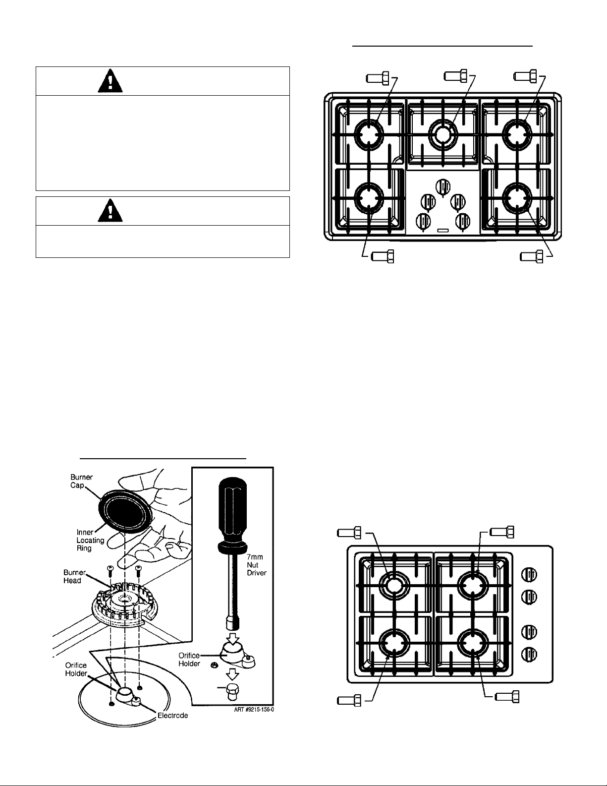
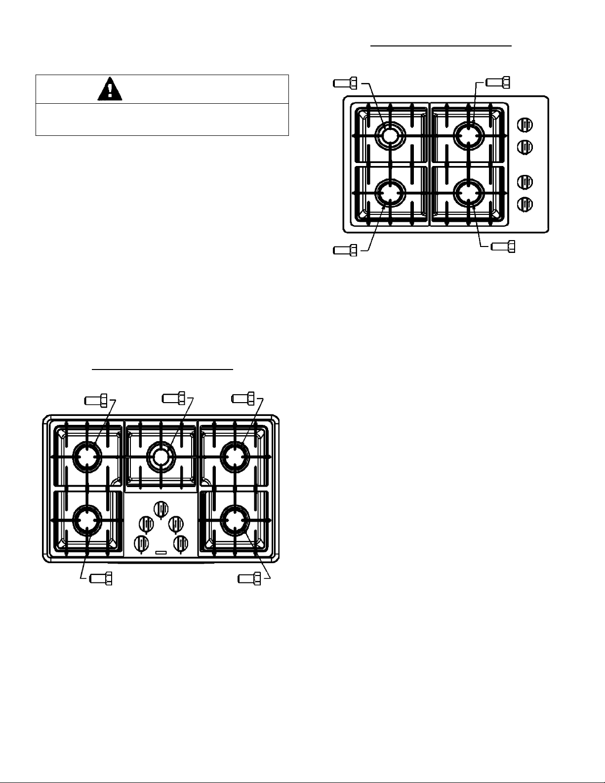
A. REPLACE ALL ORIFICE SPUDS
Step 1: Remove the grates and burner caps.
Step 2: Remove burner base by removing 2 screws.
(See figure 7).
Step 3: Firmly press 9/32″ (or 7mm) nut driver over the
orifice spud (figures 7 and 8) and loosen spud
by turning counter- clockwise. Carefully lift nut
driver out of burner throat. Orifice spud must be
captured in the nut driver. Repeat steps 2 & 3
for each burner.
REMOVAL OF ORIFICE SPUD
Installation Of LP Orifice Spud
1.01 0.64 0.91
0.91 1.14
FIGURE 9
Step 4: Locate the LP orifice spud packet included in
the literature packet. The spuds have small
numbers stamped on the side. This number
codes the orifice diameter and its correct
burner location. Figure 9 and 10 show the
correct LP orifice spud location.
Step 5: Carefully install the orifice spud in the
appropriate burner throat by turning clockwise
to tighten. T ighten to a torque of 15 to 20
inch-lbs.
Step 6: Replace burner base, caps, and grates.
Tighten screws (do not cross thread) to 25-30
in lbs.
Step 7: Save the orifices removed from the appliance
for future use.
FIGURE 7
Orifice
Spud
FIGURE 8
0.64 0.91
1.01 1.14
FIGURE 10
8
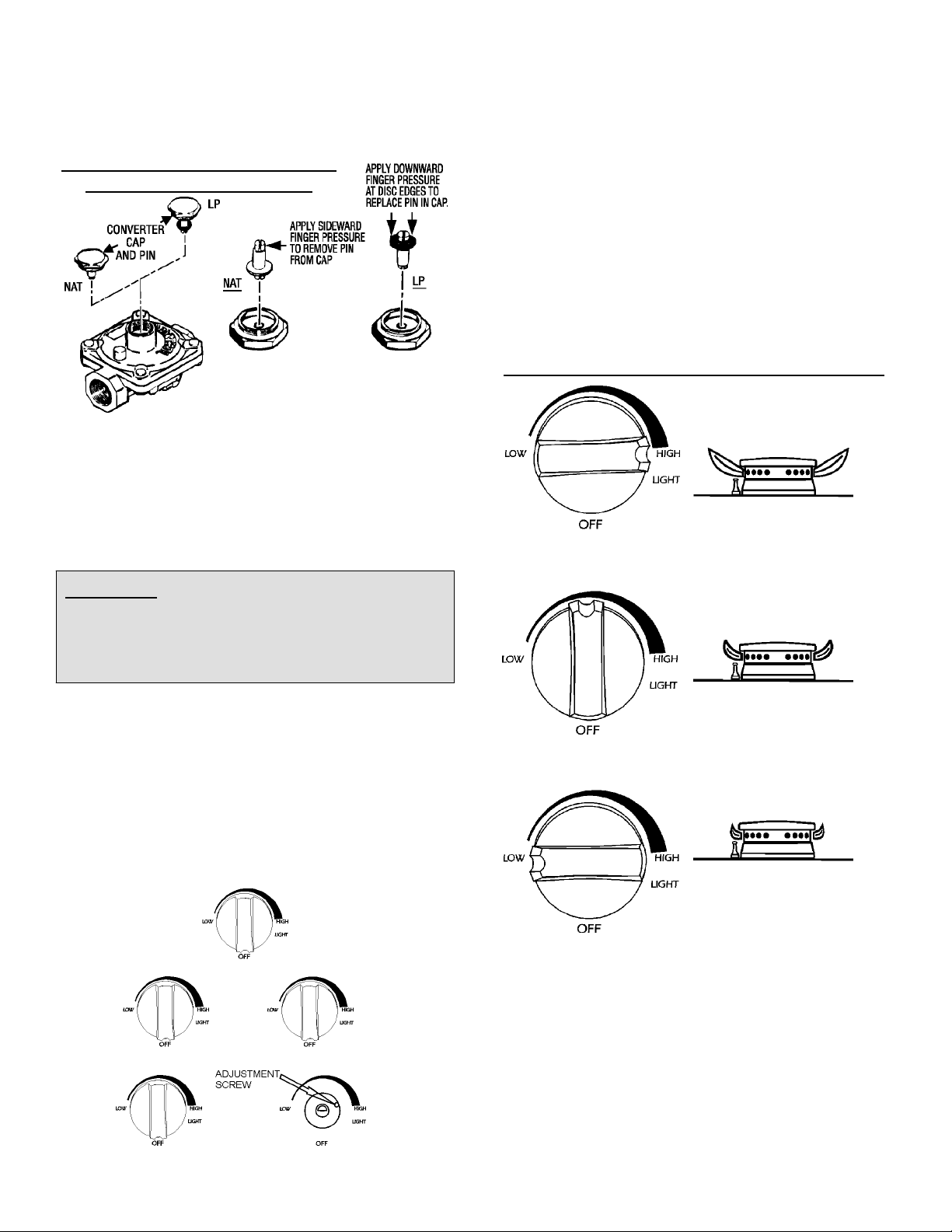
B. INVERT CAP IN APPLIANCE PRESSURE
REGULATOR (See figure 11)
With the appliance installed, the appliance regulator
should be located as shown in figure 3, 4 or 5.
CONVERSION OF APPLIANCE
PRESSURE REGULATOR
FIGURE 11
C. LOW FLAME ADJUSTMENT (See figure 12)
This appliance is shipped from the factory with low and
high flame settings adjusted for use with natural gas.
To set for use with LP proceed as follows:
After adjusting the screw the burner should produce a
stable, steady blue flame of minimum size. The setting
should be checked by turning knob from high to low
several times without extinguishing the flame.
This operation will automatically provide the proper flame
size at medium setting.
After Conversion Steps A, B and C have been completed,
check the appearance of each burner flame at the Hi and
Lo settings against figure 13. If the flames appear too
large or too small, review each step to make sure it was
completed correctly.
FLAME APPEARANCE AT HI, MED AND LOW
1. Remove control knob from valve stem.
CAUTION: NEVER USE A METAL BLADE TO PRY
KNOB OFF. IF KNOB CANNOT BE EASILY REMOVED,
TUCK THE FOLDS OF A CLOTH DISHTOWEL UNDER
THE KNOB AND PULL THE TOWEL UPWARD WITH
STEADY, EVEN PRESSURE.
2. Carefully remove rubber grommet.
3. Locate the valve adjustment screw. See figure 12.
4. Insert a slender, thin-blade screwdriver into knob
hole and engage blade with slot in adjusting screw.
5. Turn the adjusting screw clockwise until tight (5-7
in-lbs max.). Do not over tighten.
6. Replace rubber grommet and control knob.
7. Repeat for remaining burners.
KNOB
FIGURE 12
FIGURE 13
KNOB HOLE
(KNOB AND GROMMET
REMOVED)
High Altitude Notice
The specified gas burner ratings typically apply to
elevations up to 2000 feet. For higher altitudes, the rates
may need to be reduced to achieve satisfactory operation.
A local certified gas servicer will be able to advise if a
reduction is necessary.
9
To Convert Appliance For Use With
Natural Gas
WARNING
Electrical power and gas must be turned off
prior to conversion.
If this appliance has been converted for use with LP gas,
each of the following modifications must be performed to
convert the unit back to natural gas.
A. REPLACE ALL ORIFICE SPUDS.
1. Perform Steps 1 and 2 on page 8.
2. Perform Step 3 on page 8.
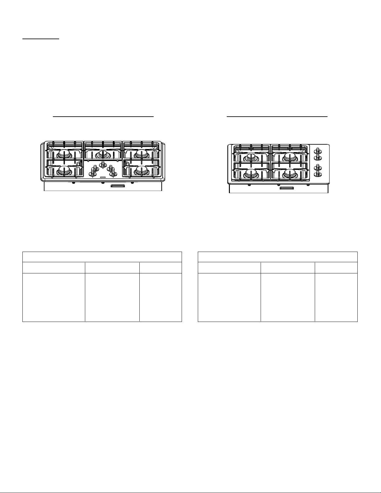
3. For Step 4: Locate the brass natural gas orifice
spuds that were originally installed in this appliance
before its conversion for use with LP gas. Observe
the number on each of the spuds and note the
correct burner location for each spud as shown in
figures 14 and 15.
Installation Of Natural Gas Orifice Spuds
5 BURNER MODEL (36″ WIDE)
1.61 1.10 1.42
4 BURNER MODEL (30″ WIDE)
1.10 1.42
1.61 2.00
FIGURE 15
4. Complete Steps 5, 6 and 7 on page 8 to complete
the installation of natural gas main spuds in their
correct locations.
5. Save the orifices removed from the appliance for
future use. They will be needed if this appliance is
again converted for use with LP gas.
B. INVERT CAP IN APPLIANCE PRESSURE
REGULATOR. (See figure 11).
With the appliance installed the appliance regulator
should be located as shown in either figure 3, 4 or 5
(pages 4, 5 & 6). Identify the type of appliance
regulator and follow the instructions in the appropriate
illustration.
1.14 2.00
FIGURE 14
C. RESET THE VALVES FOR NATURAL GAS
1. Light one burner, and set on low.
2. Remove the knob.
3. Remove the rubber grommets.
4. Locate the valve adjustment screw. See figure 12.
5. Insert a slender, thin-blade screwdriver into knob
hole and engage blade with slot in adjusting screw.
6. Starting from the LP position (see #5 on page 9,
under C. LOW FLAME ADJUSTMENT), turn the
screw counter clockwise until the flame stabilizes
and matches the pictured “low” setting on figure 13.
Proper adjustment will produce a stable, steady blue
flame of minimum size. The final adjustment should
be checked by turning the knob from high to low
several times without extinguishing the flame.
After Steps A, B and C have been completed, check
the appearance of each burner’s flame at the Hi and Lo
settings against figure 13. If the flames appear too
large or too small, make sure all steps were completed
correctly.
10
Burner Performance
CAUTION: Never cover control knobs or surrounding
control surface with utensils, towels, or other objects.
Never obstruct free air passage past the control knobs.
The knob openings have been sized to properly control air
entry to the interior of the appliance during operation.
This appliance has no air shutters. Primary air
adjustments are unnecessary. The burners are designed
to provide optimum aeration for all gases without air
shutters. When operating properly, burners should
produce clearly defined, even blue flames. If the flames
have yellow tips or are hazy and otherwise appear to
have insufficient air, obtain the services of a qualified
service technician. Some yellow tipping on LP gas is
normal.
Specified input rates are as shown in figures 16 and 17
below.
5 BURNER MODEL (36″ Wide)
FIGURE 16
JENN-AIR 36″
INPUT RATES - NATURAL GAS / LP GAS (BTU/HR)
BURNER LOCATION Hi Lo
Right Front 17,000 / 14,000 2,200/2,200
Right Rear 9,200 / 9,100 1,500 / 1,500
Left Front 9,200 / 9,200 1,500 / 1,500
Left Rear 12,000 / 10,500 1,500 / 1,500
Center 5,000 / 4,000 1,100 / 1,100
4 BURNER MODEL (30″ Wide)
FIGURE 17
JENN-AIR 30″
INPUT RATES - NATURAL GAS / LP GAS (BTU/HR)
BURNER LOCATION Hi Lo
Right Front 17,000 / 14,000 1,800 /1,800
Right Rear 9,200 / 9,100 1,300 /1,300
Left Front 12,000 / 10,500 1,300 /1,300
Left Rear 5000 / 4000 650 / 650
C e n t er -- -- -- -- -- -- -- -- -- -- -- -- -- -- -- -- -- -- -- -- -- --
11
 Loading...