

Page 1
JENN-AIR® DETAILED PLANNING DIMENSIONS
C
Wall
E*
N*
A*
B*
H
G
F
A
B
D
C
E
F
G
Floor
Wall
E*
N*
O*
A*
B*
C*
D*
H
G
F
I
J
I
H
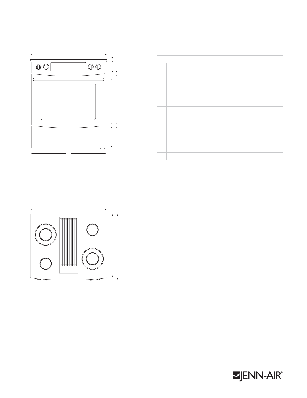
30" SLIDE-IN ELECTRIC DOWNDRAFT RANGE
JES9800CA – 303⁄4" x 36" x 287⁄8"
PRODUCT DIMENSIONS
MODEL # JES9800CA
Overall width
A
Width of door/drawer
Euro-Style Stainless or Oiled Bronze 30
B
Floating Glass 29
Height of cooking surface
C
Height of control panel 4
D
Space between door and control panel
E
Height to top of handle 18
F
Height of door 20
G
Height of lower panel 8
H
Space between door and lower panel
I
Depth to corner of control panel 24
J
Depth to center of control panel 25
K
FRONT VIEW
A
E
D
F
G
I
H
B
in cm
3
⁄4 78.1
30
1
⁄8 76.5
7
⁄8 75.9
1
⁄4 0.5
1
⁄8 10.6
5
⁄8 1.5
3
⁄4 47.5
1
⁄4 51.5
5
⁄8 22.0
5
⁄8 1.5
1
⁄4 61.5
1
⁄4 64.0
1 of 4
TOP VIEW
A
J
K
Product dimension, cutout and installation specifications are provided for planning purposes only. Before installing
any product, be sure to verify cutout dimensions and electrical/gas connections as actual product dimensions may vary.
JRC120053 03/2012
Page 2

JENN-AIR® DETAILED PLANNING DIMENSIONS
A
B
A
J
K
D
C
E
F
G
Floor
Wall
E*
N*
O*
A*
B*
C*
D*
H
G
F
I
J
I
H
O
30" SLIDE-IN ELECTRIC DOWNDRAFT RANGE
JES9800CA – 303⁄4" x 36" x 287⁄8"
DIMENSIONS AS INSTALLED
SIDE VIEW
A*
B*
C*
D*
Wall
F
G
H
E*
N*
O*
I
Floor
J
MODEL # JES9800CA
A*
B*
C*
D*
E*
F
G
H
I
J
K
L
M
OPTIONAL ACCESSORIES
N*
O*
* Add up to 13⁄4" (4.4 cm) to height with leg levelers fully extended.
2 of 4
in cm
Height to top of cooking
surface (min.)
Height to top of door (min.) 30
Height to top of handle (min.) 29
36 91.2
7
⁄8 78.5
1
⁄8 74.0
Height to top of lower panel (min.) 10 25.2
3
Height to top of countertop (min.) 35
Depth with door fully open 45
Depth with handle 28
Depth to center of control panel 26
Depth without door 24
Depth with door 26
Height of countertop channel 1
Depth from control panel notch
to countertop channel
Depth of countertop channel 1
⁄4 90.8
1
⁄2 115.5
7
⁄8 73.2
3
⁄4 68.0
1
⁄2 62.2
3
⁄8 67.0
5
⁄8 4.0
23 58.4
5
⁄8 4.0
Height to top of 6" stainless steel
backsplash (min.)
Height to top of 12" stainless steel
backsplash (min.)
3
⁄4 106.0
41
3
47
⁄4 121.3
SIDE VIEW – COUNTERTOP CHANNEL DETAIL
KL
M
Product dimension, cutout and installation specifications are provided for planning purposes only. Before installing
any product, be sure to verify cutout dimensions and electrical/gas connections as actual product dimensions may vary.
JRC120053 03/2012
Page 3

JENN-AIR® DETAILED PLANNING DIMENSIONS
Floor
Wall
E*
N*
O*
H
G
F
I
J
a
BB
Side
Cabinet
J
K
Side
Cabinet
L
v
M
N
Wall
Side
Cabinet
Side
Cabinet
f
h
i
c
b
d
e
g
a
v
Wall
Side
Cabinet
Side
Cabinet
f
h
i
c
b
d
e
g
a
J
K
v
30" SLIDE-IN ELECTRIC DOWNDRAFT RANGE
JES9800CA – 303⁄4" x 36" x 287⁄8"
OPENING/CLEARANCE DIMENSIONS
MODEL # JES9800CA
A
B
A
E*
C CD
G
e
H
FRONT VIEW – REAR WALL VENTING OPTION
J
F
v
I
K
C
D
E*
F
G
H
I
J
K
L
M
N
O
e
v
* Dimension can be reduced by 6" (15.2 cm) when bottom of wood or metal cabinet is
covered by not less than
than No. 28 MSG sheet metal, 0.015" (0.4 mm) stainless steel, 0.024" (0.6 mm) aluminum
or 0.020" (0.5 mm) copper.
ELECTRICAL REQUIREMENTS
240 volt, 60 Hz, AC only, 40-amp fused, grounded circuit is required. A dedicated
circuit is recommended. Minimum length of power cord is 36" (91.4 cm).
Width of combustible area above
cooking surface (min.)
Width from cooktop to fixed wall
or other combustible material (min.)
Width from electrical installation area
to cabinet (min.)
Width to center of vent opening option (max.)
Height to bottom of uncovered wood or
metal cabinet above cooking surface (min.)
Height to bottom of uncovered wood
or metal cabinet (min.)
Height of electrical installation area (max.)
Depth of electrical installation area (max.)
Height to center of vent opening option
Width of cutout
Depth of cutout
Depth of upper cabinet (recommended)
Depth to center of vent opening option
Height to center of vent opening option
Width to power cord
Recommended junction box location
Recommended venting location –
see page 4 for ducting information
1
⁄4" (0.6 cm) flame retardant millboard covered with not less
3 of 4
in cm
30 76.2
3 7.6
1
5
⁄2 14.0
1
2
⁄4 5.7
30 76.2
18 45.7
10 25.4
2 5.1
1
8
⁄4 20.8
30 76.2
23 58.4
13 33.0
18 45.7
1
⁄8 79.2
31
9 23.0
TOP VIEW – CUTOUT
b
c
f
g
v
Side
Cabinet
d
Wall
h
i
Side
Cabinet
e
a
b
c
d
e
f
g
h
i
in cm
1
⁄8 7.9
3
3
⁄8 21.3
8
3
⁄8 16.2
6
1
⁄2 8.9
3
1
⁄2 3.8
1
9 22.8
1
⁄4 5.7
2
1
⁄2 31.8
12
3
⁄4 47.6
18
TOP VIEW – FLOOR VENTING OPTION
Product dimension, cutout and installation specifications are provided for planning purposes only. Before installing
any product, be sure to verify cutout dimensions and electrical/gas connections as actual product dimensions may vary.
N
v
SIDE VIEW – SIDE WALL
VENTING OPTION
M
Side
Cabinet
L
O
BACK VIEW
JRC120053 03/2012
Page 4

JENN-AIR® DETAILED PLANNING DIMENSIONS
DOWNDRAFT SLIDE-IN RANGE DUCTING ARRANGEMENTS
4 of 4
DUCTING CONFIGURATIONS
5" (12.7 cm)
diameter duct
REAR DUCTING IN WALL TO ROOF
5" (12.7 cm)
diameter duct
5" (12.7 cm) diameter
1
to 3
⁄4" x 10"
(8.3 cm x 25.4 cm)
transition elbow
5" (12.7 cm)
diameter wall cap
DUCTING REQUIREMENTS
RANGE DUCT LENGTH DUCT SIZE
10' (3.0 m) or less*
Dual Fuel,
Gas
Between 10' (3.0 m)
and 60' (18.3 m)
10' (3.0 m) or less**
Electric
Between 10' (3.0 m)
and 60' (18.3 m)
* Dual fuel ranges must use 5" (12.7 cm) diameter for runs of 10' (3.0 m) or less.
** May be used to vent straight out the back of the range and directly through
the wall.
CALCULATING MAXIMUM DUCTING LENGTH
• Maximum ducting length is 60' (18.3 m).
• Each 90° elbow equals 5' (1.5 m) duct.
• Use no more than three 90° elbows.
• Flexible metal vent is not recommended.
• Do not install two elbows together.
NOTES:
• For ducting runs up to 30' (9.1 m), install range as shipped.
• For ducting runs of 31' (9.4 m) to 60' (15.2 cm), remove the
restricter ring on the blower inlet housing.
• For altitudes above 4500' (1272.0 m), reduce recommended
vent run by 20% for best performance.
5" (12.7 cm)
diameter*
6" (15.2 cm)
diameter
1
3
⁄4" x 10"
(8.3 cm x 25.4 cm)
5" (12.7 cm)
diameter**
6" (15.2 cm)
diameter
1
3
⁄4" x 10"
(8.3 cm x 25.4 cm)
REAR DUCTING THROUGH WALL TO OUTSIDE
6" (15.2 cm)
diameter elbow
5" (12.7 cm)
to 6" (15.2 cm)
diameter
transition elbow
6" (15.2 cm)
diameter wall cap
THROUGH FLOOR BETWEEN JOISTS TO OUTSIDESIDE DUCTING IN TOE KICK TO OUTSIDE
Product dimension, cutout and installation specifications are provided for planning purposes only. Before installing
any product, be sure to verify cutout dimensions and electrical/gas connections as actual product dimensions may vary.
JRC120053 03/2012
 Loading...