

Jenn-Air JES9750CAB00, JES9750CAB01, JES9750CAS00, JES9750CAS01, JES9750CAS02 Installation Guide
...
_IENN-AIRo
INSTALLATIONINSTRUCTIONS
ELECTRICDOWNDRAFTSLIDE-INRANGES
INSTRUCTI(_NSD'INSTA.LI_TION
DESCUISINIERESELECTRIQUEA EVACUATION
DESCENDANTEENCASTRABLE
Table of Contents/Table des mati_res
RANGE SAFETY ............................................................................. 2
INSTALLATION REQUIREMENTS ................................................ 3
Tools and Parts ............................................................................ 3
Location Requirements ................................................................ 3
Venting Requirements .................................................................. 5
Venting Methods .......................................................................... 5
Calculating Vent System Length .................................................. 6
Electrical Requirements - U.S.A. Only ......................................... 7
Electrical Requirements - Canada Only ....................................... 8
Countertop Preparation ............................................................... 8
INSTALLATION INSTRUCTIONS .................................................. 9
Unpack Range .............................................................................. 9
Adjust Leveling Legs .................................................................... 9
Install Anti-Tip Bracket ................................................................. 9
Install Downdraft System ........................................................... 10
Electrical Connection - U.S.A. Only ........................................... 14
Connect Range to Downdraft System ....................................... 19
Complete Installation ................................................................. 21
Moving the Range ...................................................................... 21
SI_CURITI_ DE LA CUISINII=RE ................................................... 23
EXIGENCES D'INSTALLATION ................................................... 24
Outils et pieces ........................................................................... 24
Exigences d'emplacement ......................................................... 24
Exigences concernant I'evacuation ........................................... 26
Methodes d'evacuation .............................................................. 27
Calcul de la Iongueur effective du circuit d'evacuation ............. 28
Specifications electriques .......................................................... 29
Preparation du plan de travail .................................................... 29
INSTRUCTIONS D'INSTALLATION ............................................. 30
Deballage de la cuisiniere .......................................................... 30
Reglage des pieds de nivellement ............................................. 30
Installation de la bride antibasculement .................................... 31
Installation du circuit d'evacuation par le bas ........................... 31
Raccordement de la cuisiniere au circuit d'evacuation
par le bas .................................................................................... 35
Achever I'installation .................................................................. 37
Deplacement de la cuisiniere ..................................................... 38
iMPORTANT:
Save for local electrical inspector's use.
iMPORTANT:
,&,conserver pour consultation par I'inspecteur local des installations 61ectriques.
W10253462A
RANGESAFETY
Your safety and the safety of others are very important.
We have provided many important safety messages in this manual and on your appliance. Always read and obey all safety
messages.
This is the safety alert symbol.
This symbol alerts you to potential hazards that can kill or hurt you and others.
All safety messages will follow the safety alert symbol and either the word "DANGER" or "WARNING."
These words mean:
You can be killed or seriously injured if you don't immediately
follow instructions.
You can be killed or seriously injured if you don't follow
instructions.
All safety messages will tell you what the potential hazard is, tell you how to reduce the chance of injury, and tell you what can
happen if the instructions are not followed.
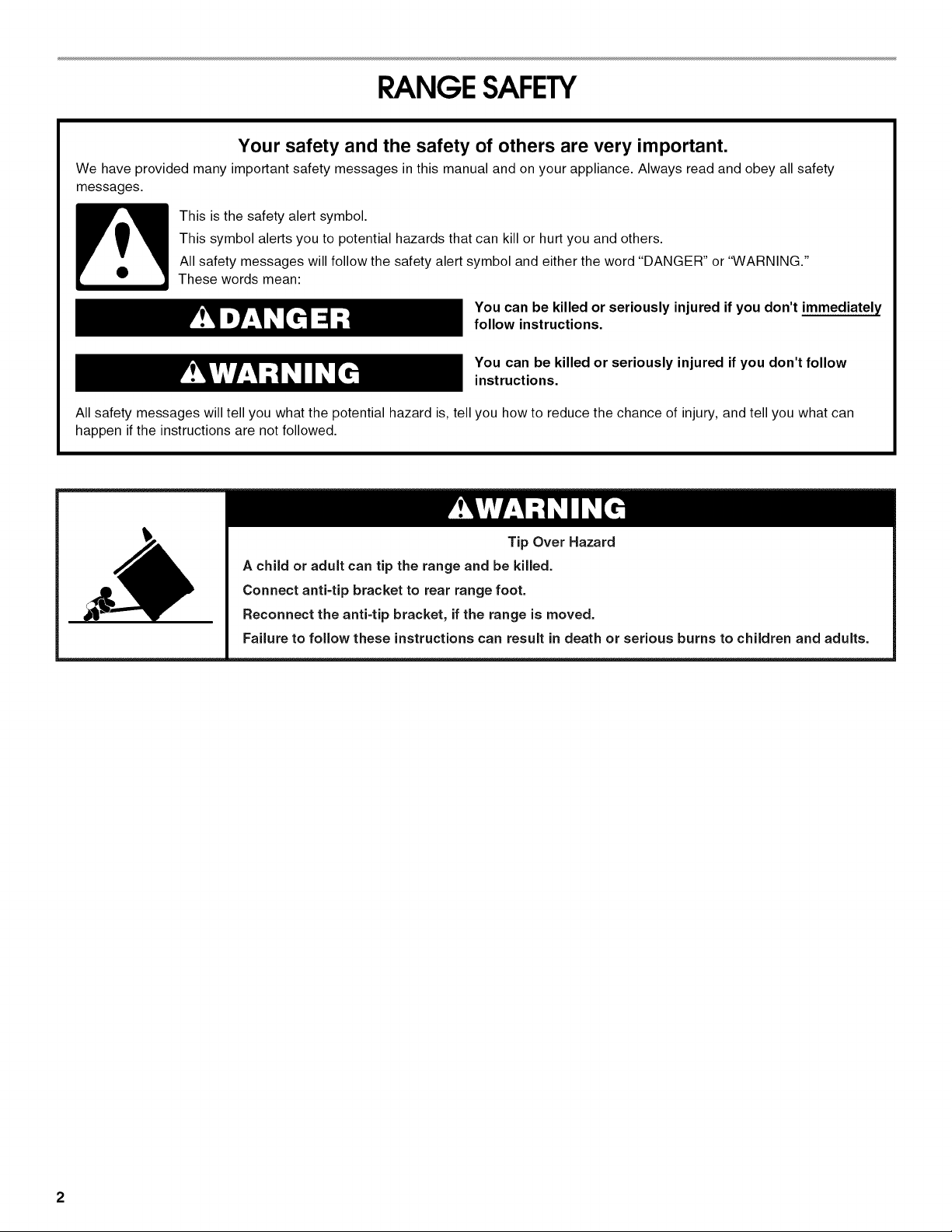
Tip Over Hazard
A child or adult can tip the range and be killed.
Connect anti=tip bracket to rear range foot.
Reconnect the anti=tip bracket, if the range is moved.
Failure to follow these instructions can result in death or serious burns to children and adults.
2
INSTALLATIONREQUIREMENTS
Gather the required tools and parts before starting installation.
Read and follow the instructions provided with any tools listed
here.
Tools needed
• Tape measure
• Level
• Phillips screwdriver
• Flat-blade screwdriver
• Saber or keyhole saw
• Marker or pencil
Parts supplied
Check that all parts are included.
3 - #10-32 hex nuts (attached to terminal block)
3 - Terminal lugs
2 or 3 - Oven racks (depending on your model)
Blower motor
2 - vent clamps
Flexible vent
Flow tester card
Blower location template
4 - #8 x 34" screws (for mounting blower motor bracket
2 - #12 x 13/8"screws (for mounting anti-tip bracket)
Anti-tip bracket (taped to package containing literature in
oven cavity)
Anti-tip bracket must be securely mounted to back wall or
floor. Thickness of floor may require longer screws to anchor
bracket to subfloor. Longer screws are available from your
local hardware store.
Parts needed
• One of the following Jenn-Air wall caps:
Jenn-Air ®5" (12.7 cm) Round Surface Wall Cap Damper.
Order Part Number A405.
Jenn-Air®6 '' (15.2 cm) Round Surface Wall Cap Damper.
Order Part Number A406.
Jenn-Air ®3W' x 10" (8.3 x 25.4 cm) Surface Wall Cap
Damper. Order Part Number A403.
To order, see the "Assistance or Service" section of the Use
and Care Guide.
• Metal ducting
• Vent clamps
• Concrete anchors (for concrete floor mounting)
• 2 - 2" x 4" x 83A'' (5.0 x 10.2 x 22.2 cm) wood spacers (for left
or right side venting)
• Wrench or pliers
• 3/ld' nut driver
• 1¼,nut driver
• Drill
• 1/8"(3.2 mm) drill bit
• 3/le"(4.8 mm) carbide-tipped
masonry drill bit (for concrete/
ceramic floors)
If using a power supply cord:
• A UL listed power supply cord kit marked for use with ranges.
The cord should be rated at 250 volts minimum, 40 amps or
50 amps that is marked for use with nominal 13/8"(3.5 cm)
diameter connection opening and must end in ring terminals
or open-end spade terminals with upturned ends.
• A UL listed strain relief.
Check local codes. Check existing electrical supply. See
"Electrical Requirements" section.
It is recommended that all electrical connections be made by a
licensed, qualified electrical installer.
IMPORTANT: Observe all governing codes and ordinances.
• It is the installer's responsibility to comply with installation
clearances specified on the model/serial rating plate. The
model/serial rating plate is located on the right-hand side of
the oven frame behind the storage drawer panel.
• The range should be located for convenient use in the
kitchen.
To eliminate the risk of burns or fire by reaching over heated
surface units, cabinet storage space located above the
surface units should be avoided. If cabinet storage is to be
provided, the risk can be reduced by installing a range hood
that projects horizontally a minimum of 5" (12.7 cm) beyond
the bottom of the cabinets.
• Cabinet opening dimensions that are shown must be used.
Given dimensions are minimum clearances.
• The floor anti-tip bracket must be installed. To install the anti-
tip bracket shipped with the range, see "Install Anti-Tip
Bracket" section.
• Grounded electrical supply is required. See "Electrical
Requirements" section.
IMPORTANT: To avoid damage to your cabinets, check with your
builder or cabinet supplier to make sure that the materials used
will not discolor, delaminate or sustain other damage. This oven
has been designed in accordance with the requirements of UL
and CSA International and complies with the maximum allowable
wood cabinet temperatures of 194°F (90°C).
Mobile Home - Additional Installation Requirements
The installation of this range must conform to the Manufactured
Home Construction and Safety Standard, Title 24 CFR, Part 3280
(formerly the Federal Standard for Mobile Home Construction
and Safety, Title 24, HUD Part 280). When such standard is not
applicable, the Standard for Manufactured Home Installations,
ANSI A225.1/NFPA 501A or with local codes.
Mobile home installations require:
• When this range is installed in a mobile home, it must be
secured to the floor during transit. Any method of securing
the range is adequate as long as itconforms to the standards
listed above.
• Four-wire power supply cord or cable must be used in a
mobile home installation. The appliance wiring will need to be
revised. See "Electrical Connection" section.
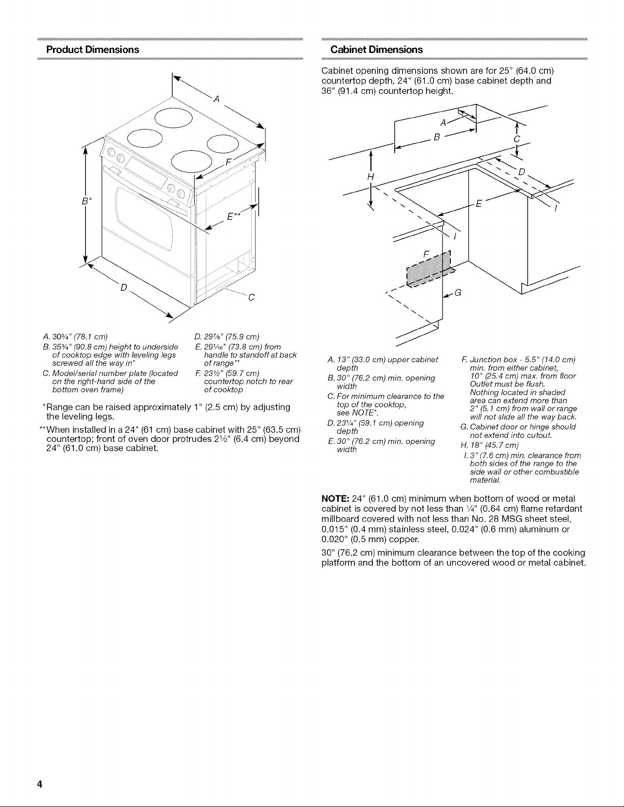
Product Dimensions Cabinet Dimensions
Cabinet opening dimensions shown are for 25" (64.0 cm)
countertop depth, 24" (61.0 cm) base cabinet depth and
36" (91.4 cm) countertop height.
H
\
C
F
A. 303/4" (78.1 cm)
B. 353/4" (90.8 cm) height to underside
of cooktop edge with levering legs
screwed all the way in*
C. Model/serial number plate (located
on the right-hand side of the
bottom oven frame)
D. 297/8'' (75.9 cm)
E. 291/18'' (73.8 cm) from
handle to standoff at back
of range**
F. 23V2" (59. 7 cm)
countertop notch to rear
of cooktop
*Range can be raised approximately 1" (2.5 cm) by adjusting
the leveling legs.
**When installed ina 24" (61 cm) base cabinet with 25" (63.5 cm)
countertop; front of oven door protrudes 21/2'' (6.4 cm) beyond
24" (61.0 cm) base cabinet.
A. 13" (33.0 cm) upper cabinet
depth
B. 30" (76.2 cm) min. opening
width
C. For minimum clearance to the
top of the cooktop,
see NOTE*.
D. 231/4"(59.1 cm) opening
depth
E. 30" (76.2 cm) min. opening
width
E Junction box - 5.5" (14.0 cm)
min. from either cabinet,
10" (25.4 cm) max. from floor
Outlet must be flush.
Nothing located in shaded
area can extend more than
2" (5.1 cm) from wall or range
will not slide all the way back.
G. Cabinet door or hinge should
not extend into cutout.
H. 18" (45.7cm)
I. 3" (7.6 cm) min. clearance from
both sides of the range to the
side wall or other combustible
material.
NOTE: 24" (61.0 cm) minimum when bottom of wood or metal
cabinet is covered by not less than 1/4"(0.64 cm) flame retardant
millboard covered with not less than No. 28 MSG sheet steel,
0.015" (0.4 mm) stainless steel, 0.024" (0.6 mm) aluminum or
0.020" (0.5 mm) copper.
30" (76.2 cm) minimum clearance between the top of the cooking
platform and the bottom of an uncovered wood or metal cabinet.
%%_'_ ' _ _" _ _ _ _ _ s_ _ ._ .I_
IMPORTANT: This range must be exhausted outdoors. See
"Venting Methods" section.
• Do not terminate the vent system in an attic or other enclosed
area.
• Use a Jenn-Air wall cap.
• Vent system must terminate to the outside.
• Use only a 6" (15.2 cm) round metal vent or a 3_¼x 10 ''
(8.3 cm x 25.4 cm) rectangular vent, except as follows:
5" (12.7 cm) round metal vent may be used for venting
straight out the back of the range and directly through the
wall for vent lengths of 10 ft (3.0 m) or less.
• Rigid metal vent is recommended. For best performance, do
not use plastic or metal foil vent.
• Before making cutouts, make sure there is proper clearance
within the wall or floor for the exhaust vent.
• Do not cut a joist or stud unless absolutely necessary. If a
joist or stud must be cut, then a supporting frame must be
constructed.
• The size of the vent should be uniform.
• The vent system must have a damper. If roof or wall cap has a
damper, do not use damper supplied with the range hood.
• Use vent clamps to seal all joints in the vent system.
• Use caulking to seal exterior wall or roof opening around the
cap.
• Determine which venting method is best for your application.
For Best Performance:
• Use 26-gauge minimum galvanized or 25-gauge minimum
aluminum metal vent. Poor quality pipe fittings can reduce
airflow. Flexible metal vent is not recommended.
NOTE: Local codes may require a heavier gauge material.
• Metal duct may be reduced to 30-gauge galvanized steel or
26-gauge aluminized steel if allowed by local codes. This
reduction is based on information in the International
Residential Codes Section M1601.1 (2006 edition).
• Do not install 2 elbows together.
• Use no more than three 90 ° elbows.
• If an elbow is used, install it as far away as possible from the
hood's vent motor exhaust opening.
• Make sure there is a minimum of 18" (45.7 cm) of straight
vent between the elbows if more than one elbow is used.
• Elbows too close together can cause excess turbulence that
reduces airflow.
• Do not use a 5" (12.7 cm) elbow in a 6" (15.2 cm) or 3V4"x 10"
(8.3 x 25.4 cm) system.
• Do not reduce to a 5" (12.7 cm) system after using a
6" (15.2 cm) or 3V4"x 10" (8.3 x 25.4 cm) fittings.
• Avoid forming handmade crimps. Handmade crimps may
restrict airflow.
• Use a Jenn-Air vent cap for proper performance. If an
alternate wall or roof cap is used, be certain the cap size is
not reduced and that it has a backdraft damper.
• Use vent clamps to seal all joints in the vent system.
• Use caulking to seal exterior wall or roof opening around the
cap.
The length of vent system and number of elbows should be kept
to a minimum to provide efficient performance.
The maximum equivalent length of the vent system is
60 ft (18.3 m). For altitudes above 4,500 ft (1272 m), reduce
recommended vent run by 20% for best performance.
Cold Weather Installations
An additional backdraft damper should be installed to minimize
backward cold air flow and a thermal break installed to minimize
conduction of outside temperatures as part of the vent system.
The damper should be on the cold air side of the thermal break.
Makeup Air
Local building codes may require the use of makeup air systems
when using ventilation systems greater than specified CFM of air
movement. The specified CFM varies from locale to locale.
Consult your HVAC professional for specific requirements in your
area.
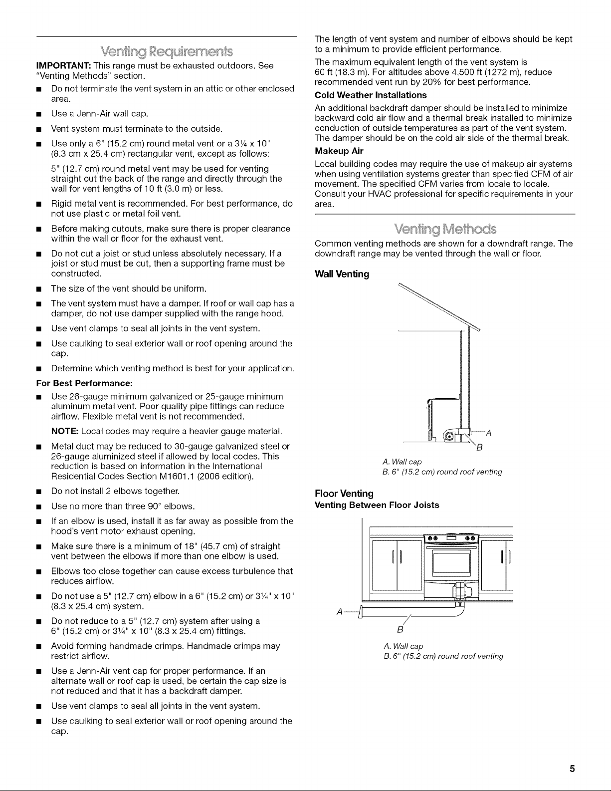
Common venting methods are shown for a downdraft range. The
downdraft range may be vented through the wall or floor.
Wall Venting
%
\B
A. Wall cap
B. 6" (15.2 cm) round roof venting
Floor Venting
Venting Between FloorJoists
O® _ QQ --
O)I
-
B
A. Wallcap
B.6" (15.2 cm)round roof venting
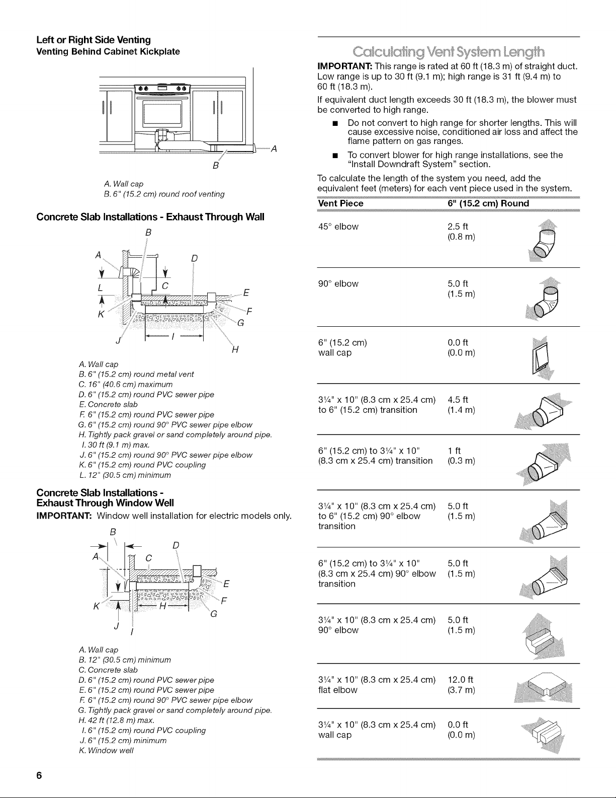
Left or Right Side Venting
Venting BehindCabinet Kickplate
m 00 r'_ Q®
/
B
A. Wall cap
B. 6" (15.2 cm) round roof venting
Concrete Slab Installations - Exhaust Through Wall
B
A
D
--A
IMPORTANT: This range is rated at 60 ff (18.3 m) of straight duct.
Low range is up to 30 ft (9.1 m); high range is 31 ff (9.4 m) to
60 ft (18.3 m).
If equivalent duct length exceeds 30 ft (18.3 m), the blower must
be converted to high range.
• Do not convert to high range for shorter lengths. This will
cause excessive noise, conditioned air loss and affect the
flame pattern on gas ranges.
• To convert blower for high range installations, see the
"Install Downdraft System" section.
To calculate the length of the system you need, add the
equivalent feet (meters) for each vent piece used in the system.
Vent Piece 6" (15.2 cm) Round
45° elbow 2.5 ft
(0.8m)
L
iiii!iiii!iii!
.......di
/
H
A. Wall cap
B. 6" (15.2 cm) round metal vent
C. 16" (40.6 cm) maximum
D. 6" (15.2 cm) round PVC sewer pipe
E. Concrete slab
F. 6" (15.2 cm) round PVC sewer pipe
G. 6" (15.2 cm) round 90 ° PVC sewer pipe elbow
H. Tightly pack gravel or sand completely around pipe.
1.30ft(9.1 m) max.
J. 6" (15.2 cm) round 90 ° PVC sewer pipe elbow
K. 6" (15.2 cm) round PVC coupling
L. 12" (30.5 cm) minimum
Concrete Slab Installations -
Exhaust Through Window Well
IMPORTANT: Window well installation for electric modelsonly.
B
D
A! /n C
90° elbow 5.0 ft
(1.5m)
6" (15.2 cm) 0.0 ft
wall cap (0.0 m)
3V4" x 10" (8.3 cm x 25.4 cm) 4.5 ft
to 6" (15.2 cm) transition (1.4 m)
6" (15.2 cm) to 3V4" x 10" 1 ft
(8.3 cm x 25.4 cm) transition (0.3 m)
3V4" x 10" (8.3 cm x 25.4 cm) 5.0 ft
to 6" (15.2 cm) 90 ° elbow (1.5 m)
transition
6" (15.2 cm) to 3V4" x 10" 5.0ft
(8.3 cm x 25.4 cm) 90° elbow (1.5 m)
transition
..... ........F
n _ I_ _ M----_t .............
J
A. Wall cap
B. 12" (30.5 cm) minimum
C. Concrete slab
D. 6" (15.2 cm) round PVC sewer pipe
E. 6" (15.2 cm) round PVC sewer pipe
F. 6" (15.2 cm) round 90 ° PVC sewer pipe elbow
G. Tightly pack gravel or sand completely around pipe.
H. 42 ft (12.8 m) max.
I. 6" (15.2 cm) round PVC coupling
J. 6" (15.2 cm) minimum
K. Window well
G
3V4" x 10" (8.3 cm x 25.4 cm) 5.0 ft
90° elbow (1.5 m)
3V4" x 10" (8.3 cm x 25.4 cm) 12.0 ft
flat elbow (3.7 m)
3V4" x 10" (8.3 cm x 25.4 cm) 0.0 ft
wall cap (0.0 m)
6
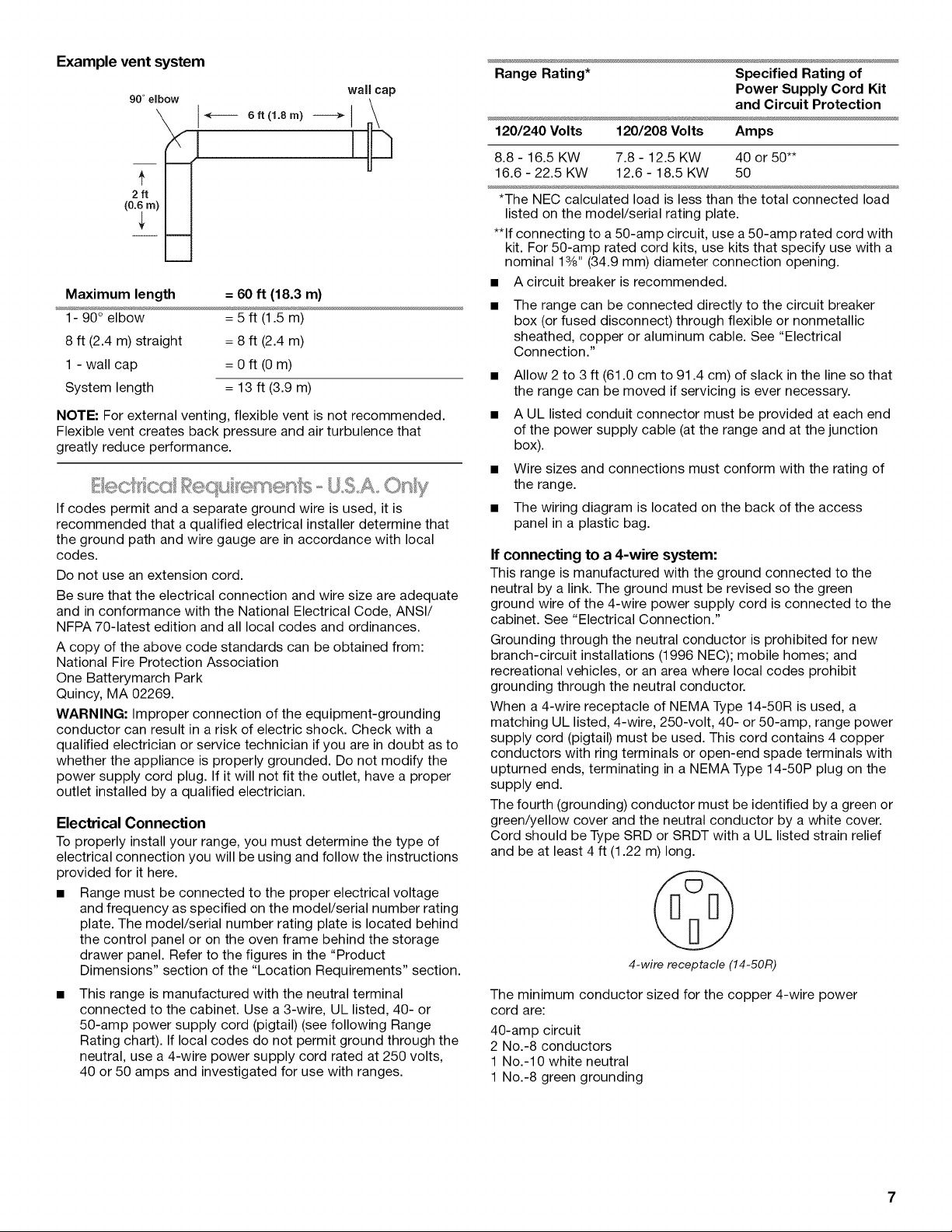
Example vent system
90 °eibow
Maximum length = 60 ft (18.3 m)
1- 90° elbow = 5 ft (1.5 m)
8 ft (2.4 m) straight = 8 ft (2.4 m)
1 - wall cap = 0 ft (0 m)
System length = 13 ft (3.9 m)
NOTE: For external venting, flexible vent is not recommended.
Flexible vent creates back pressure and air turbulence that
greatly reduce performance.
If codes permit and a separate ground wire is used, it is
recommended that a qualified electrical installer determine that
the ground path and wire gauge are in accordance with local
codes.
Do not use an extension cord.
Be sure that the electrical connection and wire size are adequate
and in conformance with the National Electrical Code, ANSI/
NFPA 70-latest edition and all local codes and ordinances.
A copy of the above code standards can be obtained from:
National Fire Protection Association
One Batterymarch Park
Quincy, MA 02269.
WARNING: Improper connection of the equipment-grounding
conductor can result in a risk of electric shock. Check with a
qualified electrician or service technician if you are in doubt as to
whether the appliance is properly grounded. Do not modify the
power supply cord plug. If it will not fit the outlet, have a proper
outlet installed by a qualified electrician.
Electrical Connection
To properly install your range, you must determine the type of
electrical connection you will be using and follow the instructions
provided for it here.
• Range must be connected to the proper electrical voltage
and frequency as specified on the model/serial number rating
plate. The model/serial number rating plate is located behind
the control panel or on the oven frame behind the storage
drawer panel. Refer to the figures in the "Product
Dimensions" section of the "Location Requirements" section.
• This range is manufactured with the neutral terminal
connected to the cabinet. Use a 3-wire, UL listed, 40- or
50-amp power supply cord (pigtail) (see following Range
Rating chart). If local codes do not permit ground through the
neutral, use a 4-wire power supply cord rated at 250 volts,
40 or 50 amps and investigated for use with ranges.
wall cap
Range Rating* Specified Rating of
Power Supply Cord Kit
and Circuit Protection
120/240 Volts 120/208 Volts Amps
8.8- 16.5 KW 7.8- 12.5 KW 40 or 50"*
16.6 - 22.5 KW 12.6 - 18.5 KW 50
*The NEC calculated load is less than the total connected load
listed on the model/serial rating plate.
**If connecting to a 50-amp circuit, use a50-amp rated cord with
kit. For 50-amp rated cord kits, use kits that specify use with a
nominal 13/8"(34.9 mm) diameter connection opening.
A circuit breaker is recommended.
The range can be connected directly to the circuit breaker
box (or fused disconnect) through flexible or nonmetallic
sheathed, copper or aluminum cable. See "Electrical
Connection."
• Allow 2 to 3 ft (61.0 cm to 91.4 cm) of slack in the line so that
the range can be moved if servicing is ever necessary.
• A UL listed conduit connector must be provided at each end
of the power supply cable (at the range and at the junction
box).
• Wire sizes and connections must conform with the rating of
the range.
• The wiring diagram is located on the back of the access
panel in a plastic bag.
If connecting to a 4-wire system:
This range is manufactured with the ground connected to the
neutral by a link. The ground must be revised so the green
ground wire of the 4-wire power supply cord is connected to the
cabinet. See "Electrical Connection."
Grounding through the neutral conductor is prohibited for new
branch-circuit installations (1996 NEC); mobile homes; and
recreational vehicles, or an area where local codes prohibit
grounding through the neutral conductor.
When a 4-wire receptacle of NEMA Type 14-50R is used, a
matching UL listed, 4-wire, 250-volt, 40- or 50-amp, range power
supply cord (pigtail) must be used. This cord contains 4 copper
conductors with ring terminals or open-end spade terminals with
upturned ends, terminating in a NEMA Type 14-50P plug on the
supply end.
The fourth (grounding) conductor must be identified by a green or
green/yellow cover and the neutral conductor by a white cover.
Cord should be Type SRD or SRDT with a UL listed strain relief
and be at least 4 ft (1.22 m) long.
4-wire receptacle (14-50R)
The minimum conductor sized for the copper 4-wire power
cord are:
40-amp circuit
2 No.-8 conductors
1 No.-10 white neutral
1 No.-8 green grounding
If connecting to a 3-wire system:
Local codes may permit the use of a UL listed, 3-wire, 250-volt,
40- or 50-amp range power supply cord (pigtail). This cord
contains 3 copper conductors with ring terminals or open-end
spade terminals with upturned ends, terminating in a NEMA Type
10-50P plug on the supply end. Connectors on the appliance end
must be provided at the point the power supply cord enters the
appliance. This uses a 3-wire receptacle of NEMA Type 10-50R.
A time-delay fuse or circuit breaker is recommended.
This range is equipped with a CSA International Certified
Power Cord intended to be plugged into a standard 14-50R
wall receptacle. Be sure the wall receptacle is within reach of
range's final location.
• Do not use an extension cord.
3-wire receptacle (10-50R)
Electrical Shock Hazard
Electrically ground range.
Failure to do so can result in death, fire, or
electrical shock.
If codes permit and a separate ground wire is used, it is
recommended that a qualified electrical installer determine that
the ground path is adequate and wire gauge are in accordance
with local codes.
Be sure that the electrical connection and wire size are adequate
and in conformance with CSA Standard C22.1, Canadian
Electrical Code, Part 1 - latest edition, and all local codes and
ordinances.
A copy of the above code standards can be obtained from:
Canadian Standards Association
178 Rexdale Blvd.
Toronto, ON M9W 1R3 CANADA
• Check with a qualified electrical installer if you are not sure
the range is properly grounded.
Coupset' op P 'epcx r£ion
(fo_"S <s@,_"/%xqges O_y;
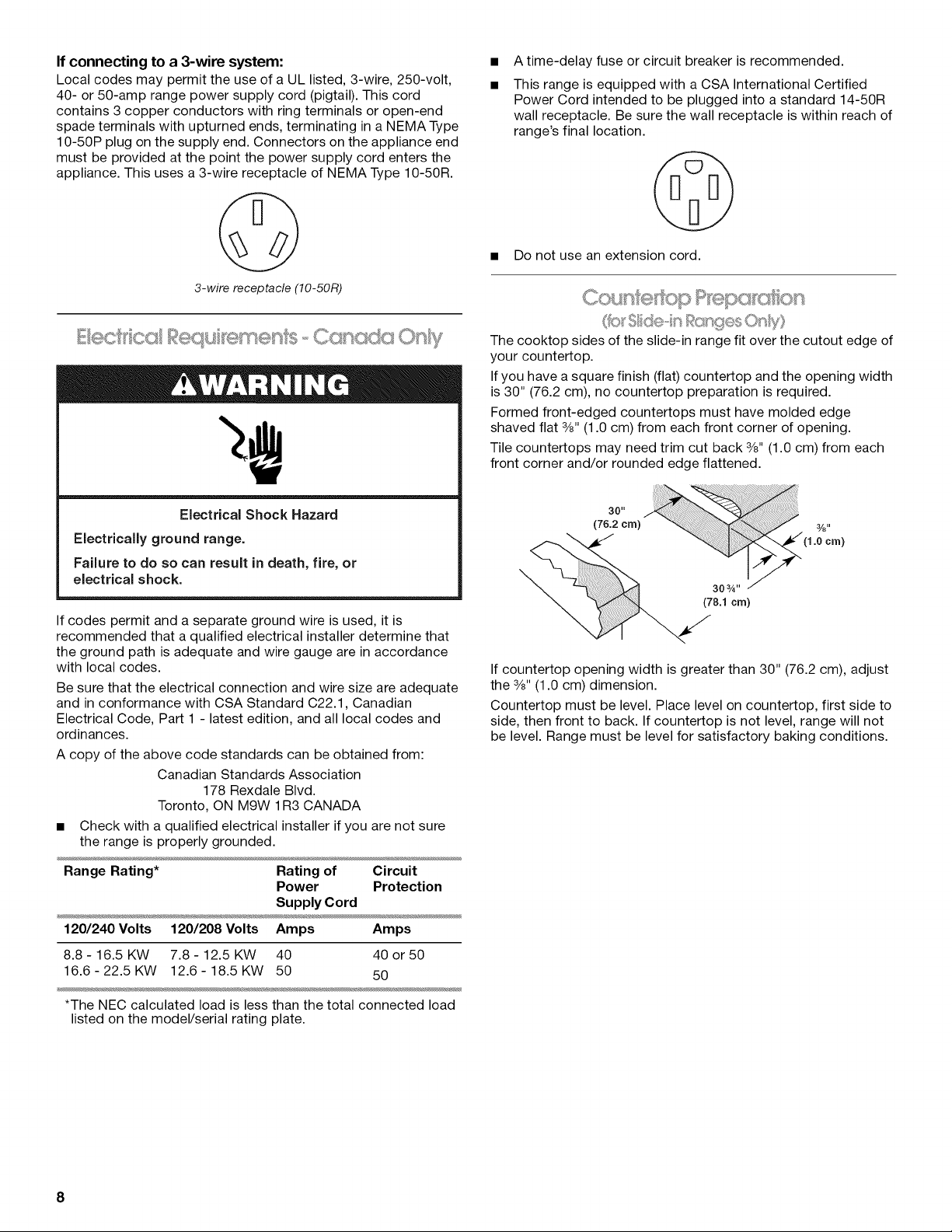
The cooktop sides of the slide-in range fit over the cutout edge of
your countertop.
If you have a square finish (flat) countertop and the opening width
is 30" (76.2 cm), no countertop preparation is required.
Formed front-edged countertops must have molded edge
shaved flat 3/8"(1.0 cm) from each front corner of opening.
Tile countertops may need trim cut back 3/8"(1.0 cm) from each
front corner and/or rounded edge flattened.
30"
(76.2 cm)
(1.o_cm)
303A"
(78.1 cm)
If countertop opening width is greater than 30" (76.2 cm), adjust
the 3/8"(1.0 cm) dimension.
Countertop must be level. Place level on countertop, first side to
side, then front to back. If countertop is not level, range will not
be level. Range must be level for satisfactory baking conditions.
Range Rating* Rating of Circuit
Power Protection
Supply Cord
120/240 Volts 120/208 Volts Amps Amps
8.8 - 16.5 KW 7.8 - 12.5 KW 40 40 or 50
16.6-22.5KW 12.6-18.5KW 50 50
*The NEC calculated load is less than the total connected load
listed on the model/serial rating plate.
8
INSTALLATIONINSTRUCTIONS
Excessive Weight Hazard
Use two or more people to move and install range.
Failure to do so can result in back or other injury.
NOTE: If height adjustment is made when range is standing,
tilt the range back to adjust the front legs, then tilt forward to
adjust the rear legs.
3.
When the range is at the correct height, check that there is
adequate clearance under the range for the anti-tip bracket.
Before sliding range into its final location, check that the anti-
tip bracket will slide under the range and onto the rear
leveling leg prior to anti-tip bracket installation.
1. Remove shipping materials, tape and film from the range.
Keep cardboard bottom under range.
2. Remove oven racks and parts package from inside oven.
3. To remove cardboard bottom, place range on its back, take
4 cardboard corners from the carton. Stack one cardboard
corner on top of another. Repeat with the other 2 corners.
Place them lengthwise on the floor behind the range to
support the range when it is laid on its back.
4. Using 2 or more people, firmly grasp the range and gently lay
it on its back on the cardboard corners.
5. Pull cardboard bottom firmly to remove.
6. Use an adjustable wrench to loosen the leveling legs.
7. Place cardboard or hardboard in front of range. Using 2 or
more people, stand range back up onto cardboard or
hardboard.
1.
If range height adjustment is necessary, use a wrench or
pliers to loosen the 4 leveling legs.
This may be done with the range on its back or with the range
supported on 2 legs after the range has been placed back to
a standing position.
NOTE: To place range back up into a standing position, put a
sheet of cardboard or hardboard in front of range. Using 2 or
more people, stand range back up onto the cardboard or
hardboard.
1. Remove the anti-tip bracket that is taped to the package
containing literature.
2. Determine which mounting method to use: floor or wall.
If you have a stone or masonry floor you can use the wall
mounting method.
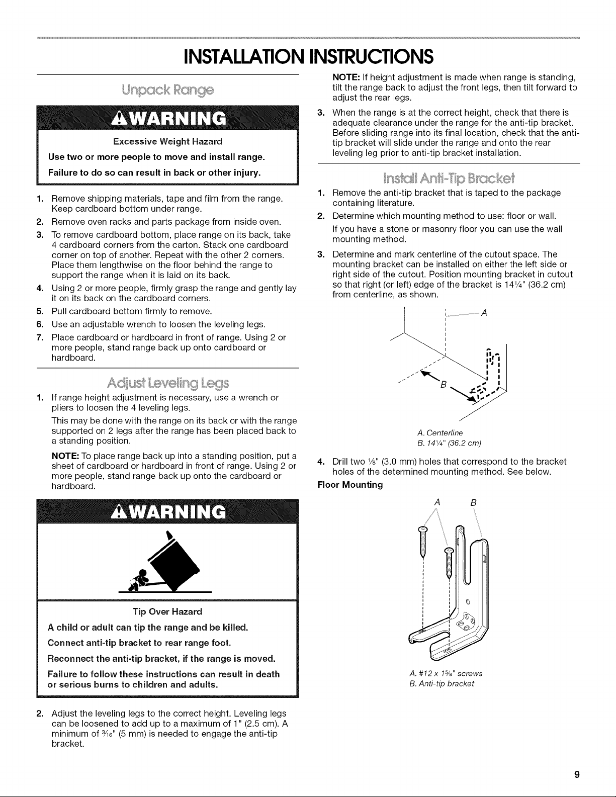
3. Determine and mark centerline of the cutout space. The
mounting bracket can be installed on either the left side or
right side of the cutout. Position mounting bracket in cutout
so that right (or left) edge of the bracket is 14¼" (36.2 cm)
from centerline, as shown.
J _ i°I i
ii. i' I
I I
_
A. Centerline
B. 141/4'' (36.2 cm)
4. Drill two V8"(3.0 mm) holes that correspond to the bracket
holes of the determined mounting method. See below.
Floor Mounting
A B
Tip Over Hazard
A child or adult can tip the range and be killed.
Connect anti=tip bracket to rear range foot.
Reconnect the anti=tip bracket, if the range is moved.
Failure to follow these instructions can result in death
or serious burns to children and adults.
2.
Adjust the leveling legs to the correct height. Leveling legs
can be loosened to add up to a maximum of 1" (2.5 cm). A
minimum of 3Ad'(5 mm) is needed to engage the anti-tip
bracket.
% %
A. #12 x 1%" screws
B.Anti-tip bracket
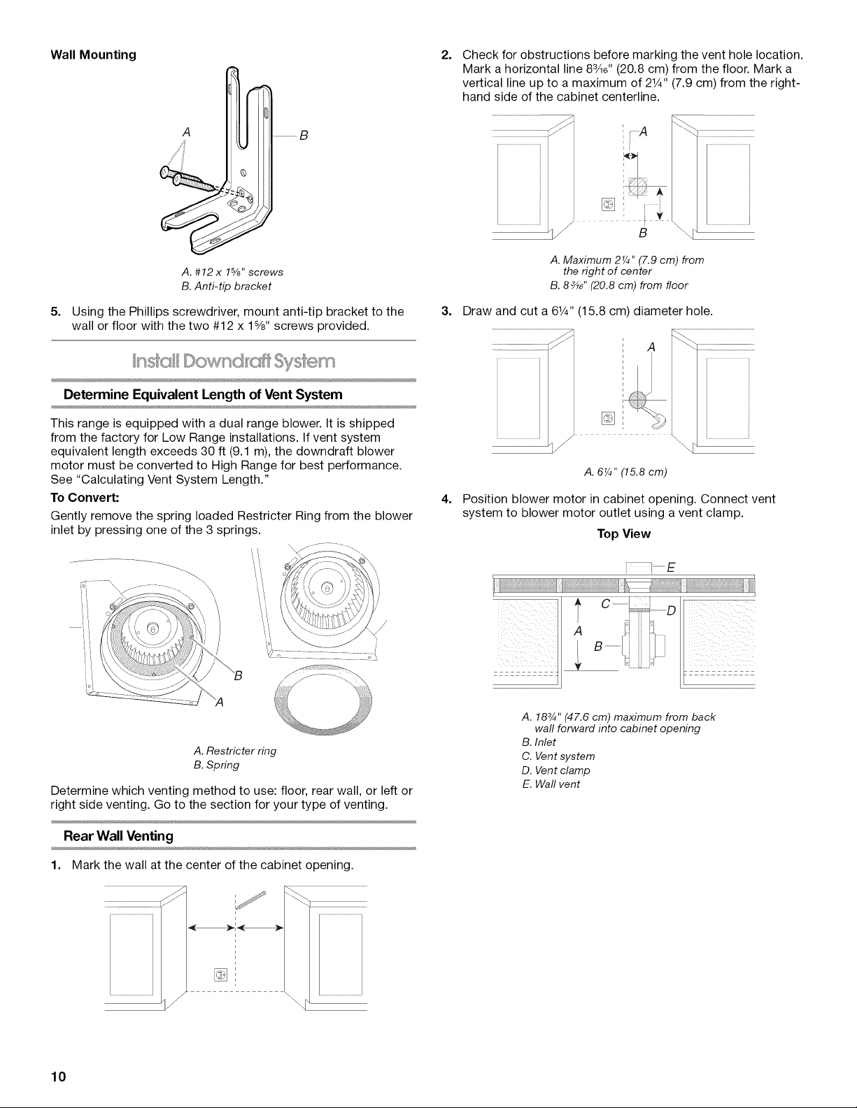
Wall Mounting
2.
Check for obstructions before marking the vent hole location.
Mark a horizontal line 83/le'' (20.8 cm) from the floor. Mark a
vertical line up to a maximum of 21¼'' (7.9 cm) from the right-
hand side of the cabinet centerline.
s _
A. #12 x 1%" screws
B. Anti-tip bracket
5. Using the Phillips screwdriver, mount anti-tip bracket to the
wall or floor with the two #12 x 1%" screws provided.
n ©ownd m
Determine Equivalent Length of Vent System
This range is equipped with a dual range blower. It is shipped
from the factory for Low Range installations. If vent system
equivalent length exceeds 30 ft (9.1 m), the downdraft blower
motor must be converted to High Range for best performance.
See "Calculating Vent System Length."
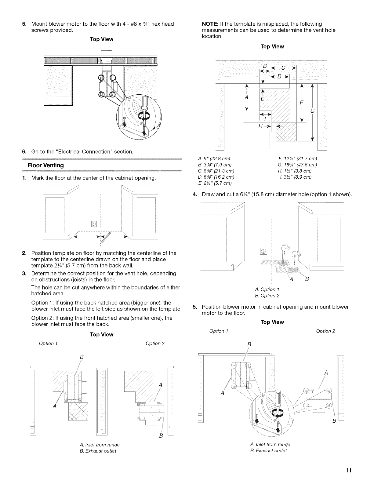
To Convert:
Gently remove the spring loaded Restricter Ring from the blower
inlet by pressing one of the 3 springs.
J
A. Maximum 2¼" (7.9 cm) from
the right of center
B. 8_" (20.8 cm) from floor
B
3. Draw and cut a 61¼"(15.8 cm) diameter hole.
A
i
[]
A. 6¼" (15.8 cm)
4,
Position blower motor in cabinet opening. Connect vent
system to blower motor outlet using a vent clamp.
Top View
A
ii ii
;B
A. Restricter ring
B. Spring
Determine which venting method to use: floor, rear wall, or left or
right side venting. Go to the section for your type of venting.
Rear Wall Venting
1. Mark the wall at the center of the cabinet opening.
/J
i
i
.........................................=
\
10
A. 183/4'' (47.6 cm) maximum from back
wall forward into cabinet opening
B. Inlet
C. Vent system
D. Vent clamp
E. Wall vent
5. Mount blower motor to the floor with 4 - #8 x 3_,,hex head
screws provided.
Top View
JZZ2
6. Go to the "Electrical Connection" section.
Floor Venting
1. Mark the floor at the center of the cabinet opening.
NOTE: If the template is misplaced, the following
measurements can be used to determine the vent hole
location.
Top View
F I
I G
A. 9" (22.8 cm)
B. 3 _" (7.9 cm)
C. 8_" (21.3 cm)
D. 6_" (16.2 cm)
E. 2¼ " (5.7 cm)
F. 12Y2" (31.7 cm)
G. 183/4" (47.6 cm)
H. lY2" (3.8 cm)
I. 3Y2" (8.9 cm)
4. Draw and cut a 61¼'' (15.8 cm) diameter hole (option 1 shown).
2. Position template on floor by matching the centerline of the
template to the centerline drawn on the floor and place
template 21¼'' (5.7 cm) from the back wall.
3. Determine the correct position for the vent hole, depending
on obstructions (joists) in the floor.
The hole can be cut anywhere within the boundaries of either
hatched area.
Option 1: If using the back hatched area (bigger one), the
blower inlet must face the left side as shown on the template
Option 2: If using the front hatched area (smaller one), the
blower inlet must face the back.
Top View
Option 1 Option 2
B
_r
I
A
A
A. Option 1
B. Option 2
5.
Position blower motor in cabinet opening and mount blower
motor to the floor.
Top View
Option 1 Option 2
i......
A
A. Inlet from range
B. Exhaust outlet
B
A. Inlet from range
B. Exhaust outlet
11
6. Connect vent system to blower motor outlet (option 1 shown)
with 4 - #8 x 3_,,hex head screws provided.
A. Inlet
B. Vent clamp
C. Floor
D. Vent system
7. Go to the "Electrical Connection" section.
Left or Right Side Venting
1. Mark cabinet side for either a left or right side vent hole
location.
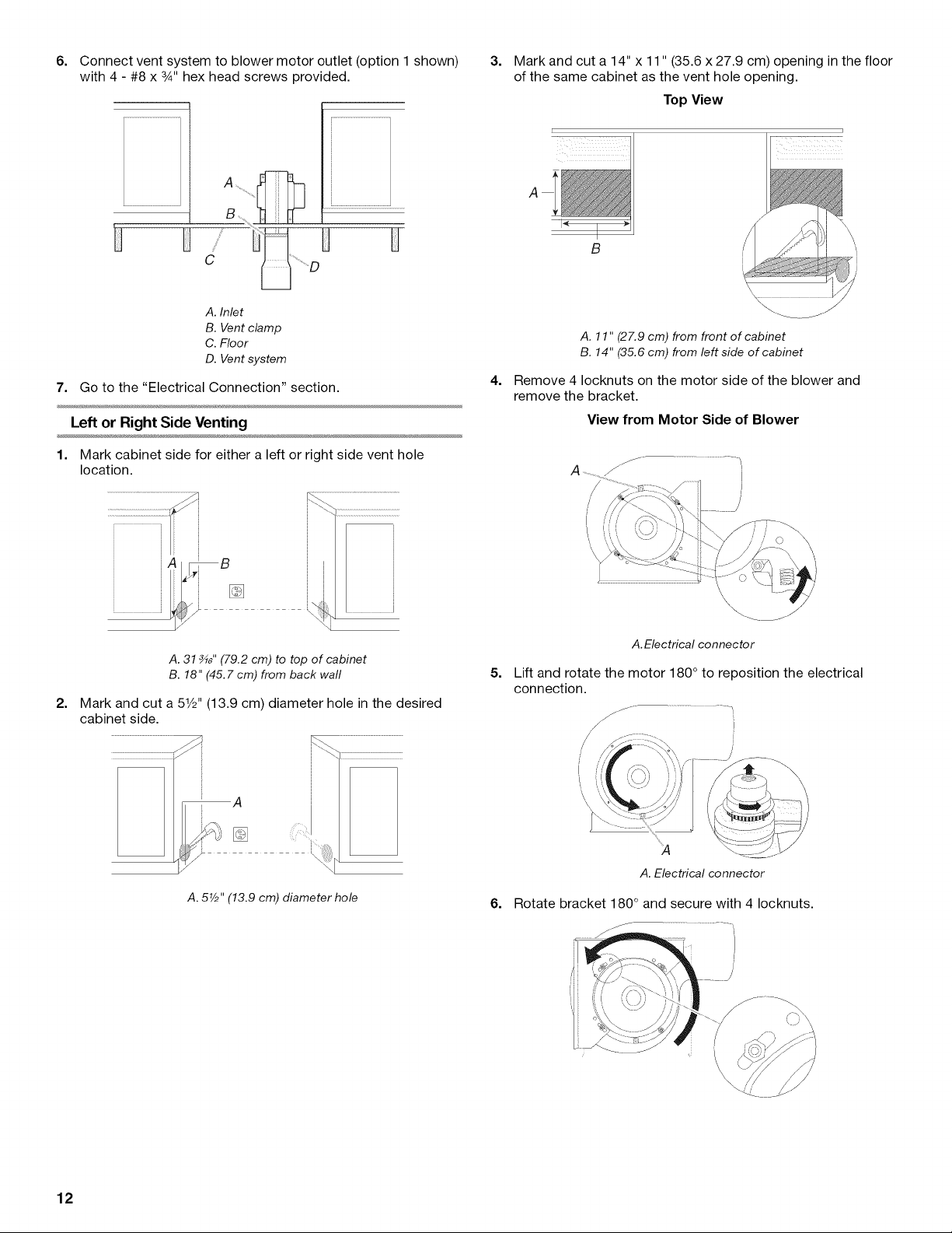
3=
Mark and cut a 14" x 11" (35.6 x 27.9 cm) opening in the floor
of the same cabinet as the vent hole opening.
Top View
A. 11" (27.9 cm) from front of cabinet
B. 14" (35.6 cm) from left side of cabinet
4=
Remove 4 Iocknuts on the motor side of the blower and
remove the bracket.
View from Motor Side of Blower
A. 31 _" (79.2 cm) to top of cabinet
B. 18" (45.7 cm) from back wall
2=
Mark and cut a 51/2"(13.9 cm) diameter hole in the desired
cabinet side.
A. 5V2" (13.9 cm) diameter hole
A.Electrical connector
5=
Lift and rotate the motor 180° to reposition the electrical
connection.
/
A.Electrical connector
6. Rotate bracket 180 ° and secure with 4 Iocknuts.
12
7=
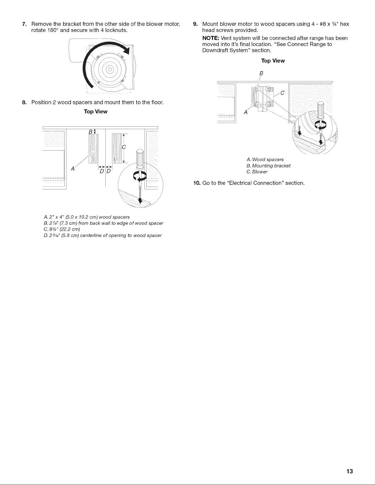
Remove the bracket from the other side of the blower motor,
rotate 180 ° and secure with 4 Iocknuts.
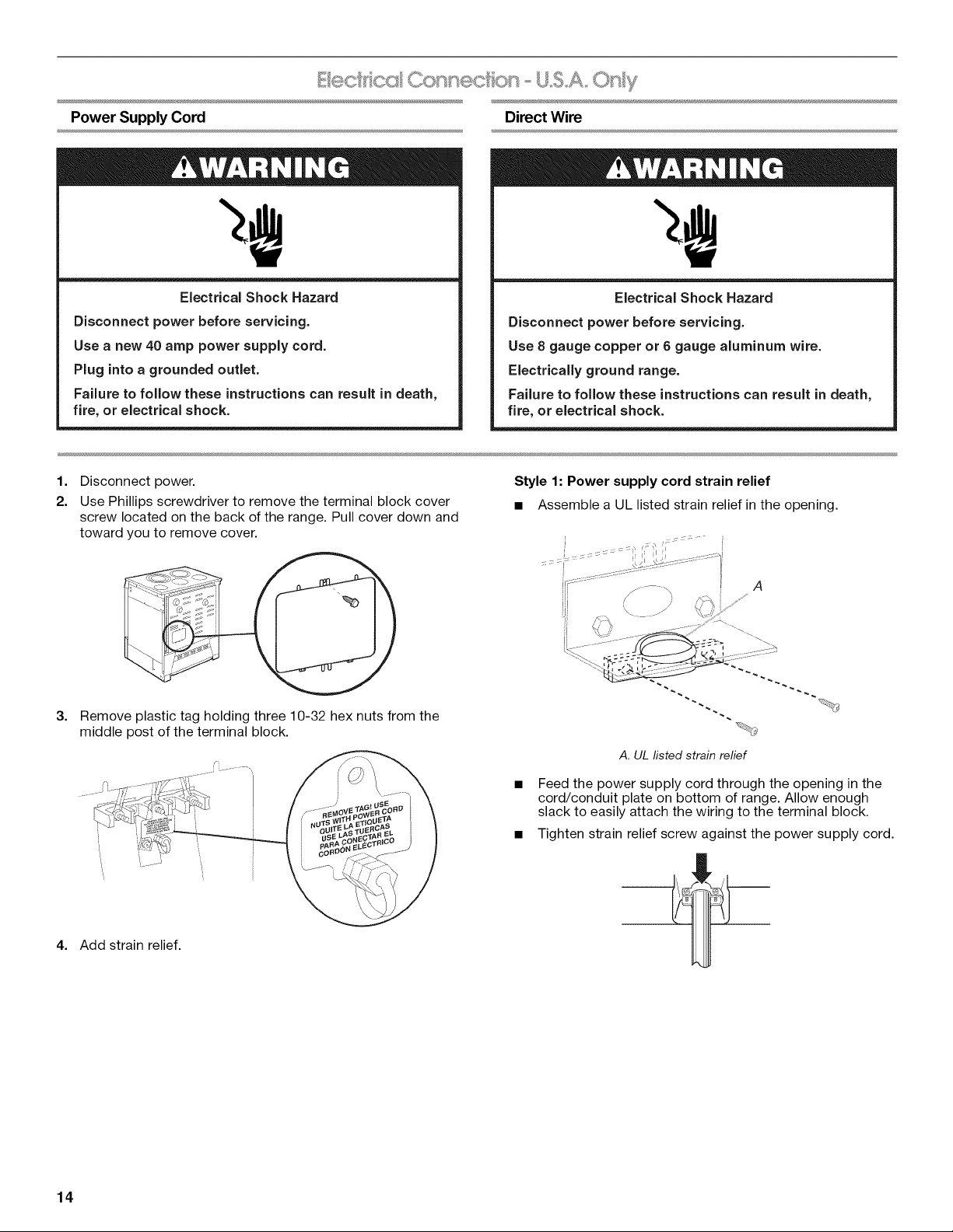
8. Position 2 wood spacers and mount them to the floor.
Top View
9.
Mount blower motor to wood spacers using 4 - #8 x 3A" hex
head screws provided.
NOTE: Vent system will be connected after range has been
moved into it's final location. "See Connect Range to
Downdraft System" section.
Top View
B
j_
F
B_
iii
/
/
A. 2" x 4" (5.0 x 10.2 cm) wood spacers
B. 2 _" (7.3 cm) from back wall to edge of wood spacer
C. 83_" (22.2 cm)
D. 2 _" (5.8 cm) centerline of opening to wood spacer
A. Wood spacers
B. Mounting bracket
C. Blower
10. Go to the "Electrical Connection" section.
J
/
/
/
13
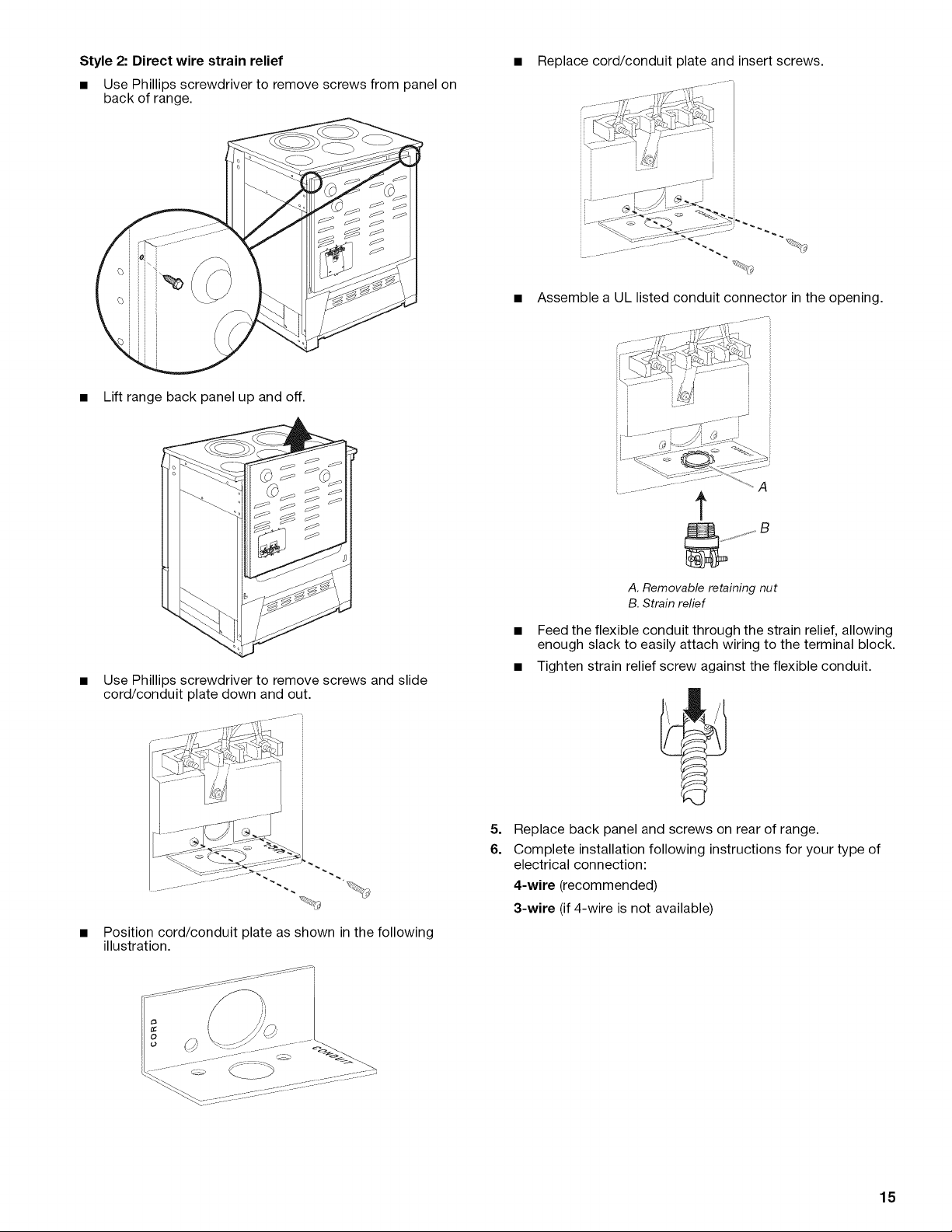
Power Supply Cord Direct Wire
Electrical Shock Hazard
Disconnect power before servicing.
Use a new 40 amp power supply cord.
Plug into a grounded outlet.
Failure to follow these instructions can result in death,
fire, or electrical shock.
1=
Disconnect power.
2.
Use Phillips screwdriver to remove the terminal block cover
screw located on the back of the range. Pull cover down and
toward you to remove cover.
3.
Remove plastic tag holding three 10-32 hex nuts from the
middle post of the terminal block.
Electrical Shock Hazard
Disconnect power before servicing.
Use 8 gauge copper or 6 gauge aluminum wire.
Electrically ground range.
Failure to follow these instructions can result in death,
fire, or electrical shock.
Style 1: Power supply cord strain relief
• Assemble a UL listed strain relief in the opening.
A
A. UL listed strain relief
4. Add strain relief.
14
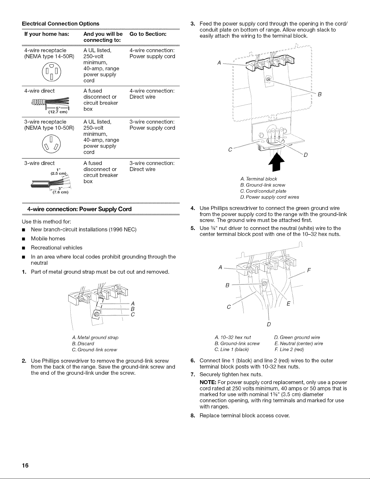
Feed the power supply cord through the opening in the
cord/conduit plate on bottom of range. Allow enough
slack to easily attach the wiring to the terminal block.
• Tighten strain relief screw against the power supply cord.
Style 2: Direct wire strain relief
• Use Phillips screwdriver to remove screws from panel on
back of range.
• Lift range back panel up and off.
• Replace cord/conduit plate and insert screws.
Assemble a UL listed conduit connector in the opening.
F..............
!
t
Use Phillips screwdriver to remove screws and slide
cord/conduit plate down and out.
Position cord/conduit plate as shown in the following
illustration.
A. Removableretaining nut
B.Strainrelief
• Feed the flexible conduit through the strain relief, allowing
enough slack to easily attach wiring to the terminal block.
• Tighten strain relief screw against the flexible conduit.
5=
Replace back panel and screws on rear of range.
6.
Complete installation following instructions for your type of
electrical connection:
4-wire (recommended)
3-wire (if 4-wire is not available)
15
Electrical Connection Options 3.
If your home has: And you will be Go to Section:
connecting to:
4-wire receptacle A UL listed, 4-wire connection:
(NEMA type 14-50R) 250-volt Power supply cord
40-amp, range
minimum,
power supply
cord
4-wire direct A fused 4-wire connection:
disconnect or Direct wire
circuit breaker
(12.7 crn)
3-wire receptacle A UL listed,
(NEMA type 10-50R) 250-volt
box
3-wire connection:
Power supply cord
minimum,
power supply
40-amp, range
cord
3-wire direct A fused
1" disconnect or
3-wire connection:
Direct wire
circuitboxbreaker
Feed the power supply cord through the opening in the cord/
conduit plate on bottom of range. Allow enough slack to
easily attach the wiring to the terminal block.
//
C
D
A. Terminal block
B. Ground-link screw
C. Cord/conduit plate
D. Power supply cord wires
4-wire connection: Power Supply Cord
Use this method for:
• New branch-circuit installations (1996 NEC)
• Mobile homes
• Recreational vehicles
• In an area where local codes prohibit grounding through the
neutral
1. Part of metal ground strap must be cut out and removed.
A
B
C
A. Metal ground strap
B. Discard
C. Ground-link screw
2=
Use Phillips screwdriver to remove the ground-link screw
from the back of the range. Save the ground-link screw and
the end of the ground-link under the screw.
4. Use Phillips screwdriver to connect the green ground wire
from the power supply cord to the range with the ground-link
screw. The ground wire must be attached first.
5. Use 3/8"nut driver to connect the neutral (white) wire to the
center terminal block post with one of the 10-32 hex nuts.
F
D
A. 10-32 hex nut
B. Ground-link screw
C. Line 1 (black)
6=
Connect line 1 (black) and line 2 (red) wires to the outer
D. Green ground wire
E. Neutral (center) wire
F. Line 2 (red)
terminal block posts with 10-32 hex nuts.
7.
Securely tighten hex nuts.
NOTE: For power supply cord replacement, only use a power
cord rated at 250 volts minimum, 40 amps or 50 amps that is
marked for use with nominal 13/8"(3.5 cm) diameter
connection opening, with ring terminals and marked for use
with ranges.
8=
Replace terminal block access cover.
16

3-wire connection: Power Supply Cord
Direct Wire Installation: Copper or Aluminum Wire
Use this method only if local codes permit connecting chassis
ground conductor to neutral wire of power supply cord.
1. Feed the power supply cord through the opening in the cord/
conduit plate on bottom of range. Allow enough slack to
easily attach the wiring to the terminal block.
. d ........... I
...... /! '-- II
i: ......................I
B
i
C
A. Terminal block
B. Ground-link screw
C. Cord/conduit plate
D. Power supply cord wires
2.
Use 3/8"nut driver to connect the neutral (white) wire to the
center terminal block post with one of the 10-32 hex nuts.
This range may be connected directly to the fuse disconnect or
circuit breaker box. Depending on your electrical supply, make
the required 3-wire or 4-wire connection.
1. Strip outer covering back 3" (7.6 cm) to expose wires. Strip
the insulation back 1" (2.5 cm) from the end of each wire.
1 "
(2.5cm) ..
3" ..... "
(7.6 crn)
2. Allow enough slack in the wire to easily attach the wiring
terminal block.
3. Complete electrical connection according to your type of
electrical supply (4-wire or 3-wire connection).
4-wire Connection: Direct Wire
Use this method for:
• New branch-circuit installations (1996 NEC)
• Mobile homes
• Recreational vehicles
• In an area where local codes prohibit grounding through the
neutral
1. Part of metal ground strap must be cut out and removed.
A
B
C
A
E
C
A. 10-32 hex nut
B. Line 1 (black)
C. Ground-link screw
D. Neutral (white) wire
E.Line 2 (red)
3. Connect line 1 (black) and line 2 (red) wires to the outer
terminal block posts with 10-32 hex nuts.
4. Securely tighten hex nuts.
NOTE: For power supply cord replacement, only use a power
cord rated at 250 volts minimum, 40 amps or 50 amps that is
marked for use with nominal 13/8"(3.5 cm) diameter
connection opening, with ring terminals and marked for use
with ranges.
5. Replace terminal block access cover.
A.Metal ground strap
B.Discard
C.Ground-link screw
2.
Use Phillips screwdriver to remove the ground-link screw
from the back of the range. Save the ground-link screw and
the end of the ground-link under the screw.
17
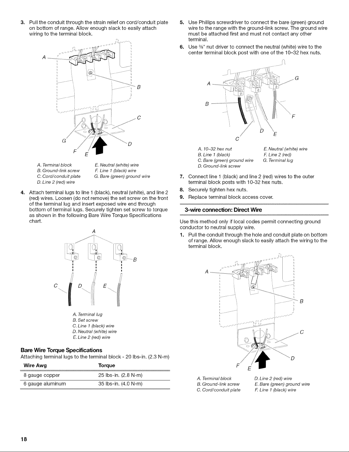
3.
C
G
A. Terminal block
B. Ground-link screw
C. Cord/conduit plate
D. Line 2 (red) wire
4=
Attach terminal lugs to line 1 (black), neutral (white), and line 2
E. Neutral (white) wire
F. Line 1 (black) wire
G. Bare (green) ground wire
(red) wires. Loosen (do not remove) the set screw on the front
of the terminal lug and insert exposed wire end through
bottom of terminal lugs. Securely tighten set screw to torque
as shown in the following Bare Wire Torque Specifications
chart.
5. Use Phillips screwdriver to connect the bare (green) ground
wire to the range with the ground-link screw. The ground wire
must be attached first and must not contact any other
terminal.
6. Use 3/8"nut driver to connect the neutral (white) wire to the
center terminal block post with one of the 10-32 hex nuts.
i,
F
A. 10-32 hex nut
B. Line 1 (black)
C. Bare (green) ground wire
D. Ground-link screw
E. Neutral (white) wire
F. Line 2 (red)
G. Terminal lug
7. Connect line 1 (black) and line 2 (red) wires to the outer
terminal block posts with 10-32 hex nuts.
8. Securely tighten hex nuts.
9. Replace terminal block access cover.
3-wire connection: Direct Wire
Use this method only if local codes permit connecting ground
conductor to neutral supply wire.
1. Pull the conduit through the hole and conduit plate on bottom
of range. Allow enough slack to easily attach the wiring to the
terminal block.
C
A. Terminal lug
B. Set screw
C. Line 1 (black) wire
D. Neutral (white) wire
E.Line 2 (red) wire
Bare Wire Torque Specifications
Attaching terminal lugs to the terminal block - 20 Ibs-in. (2.3 N-m)
Wire Awg Torque
8 gauge copper 25 Ibs-in. (2.8 N-m)
6 gauge aluminum 35 Ibs-in. (4.0 N-m)
A. Terminal block
B. Ground-link screw
C. Cord/conduit plate
Ii
Jl
I //
C
F
D. Line 2 fled) wire
E. Bare (green) ground wire
F. Line 1 (black) wire
18
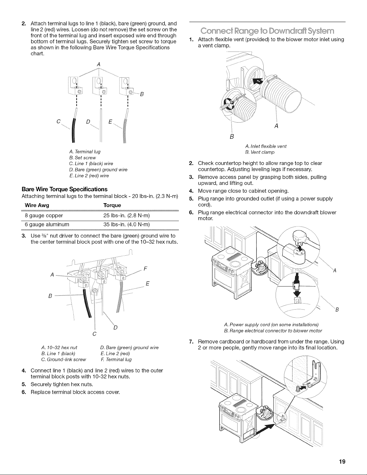
2.
Attach terminal lugs to line 1 (black), bare (green) ground, and
line 2 (red) wires. Loosen (do not remove) the set screw on the
front of the terminal lug and insert exposed wire end through
bottom of terminal lugs. Securely tighten set screw to torque
as shown in the following Bare Wire Torque Specifications
chart.
A. Terminal lug
B. Set screw
C. Line 1 (black) wire
D. Bare (green) ground wire
E.Line 2 (red) wire
Bare Wire Torque Specifications
Attaching terminal lugs to the terminal block - 20 Ibs-in. (2.3 N-m)
Wire Aw9 Torque
8 gauge copper 25 Ibs-in. (2.8 N-m)
6 gauge aluminum 35 Ibs-in. (4.0 N-m)
1.
Attach flexible vent (provided) to the blower motor inlet using
a vent clamp.
A
B
A. Inlet flexible vent
B. Vent clamp
2. Check countertop height to allow range top to clear
countertop. Adjusting leveling legs if necessary.
3. Remove access panel by grasping both sides, pulling
upward, and lifting out.
4. Move range close to cabinet opening.
5. Plug range into grounded outlet (if using a power supply
cord).
6. Plug range electrical connector into the downdraft blower
motor.
3. Use 3/8"nut driver to connect the bare (green) ground wire to
the center terminal block post with one of the 10-32 hex nuts.
F
A
E
B
D
C
A. 10-32 hex nut
B. Line 1 (black)
C. Ground-link screw
D. Bare (green) ground wire
E.Line 2 (red)
F. Terminal lug
4. Connect line 1 (black) and line 2 (red) wires to the outer
terminal block posts with 10-32 hex nuts.
5. Securely tighten hex nuts.
6. Replace terminal block access cover.
\ J ............ j
A. Power supply cord (on some installations)
B. Range electrical connector to blower motor
7.
Remove cardboard or hardboard from under the range. Using
2 or more people, gently move range into its final location.
....A
.....B
19
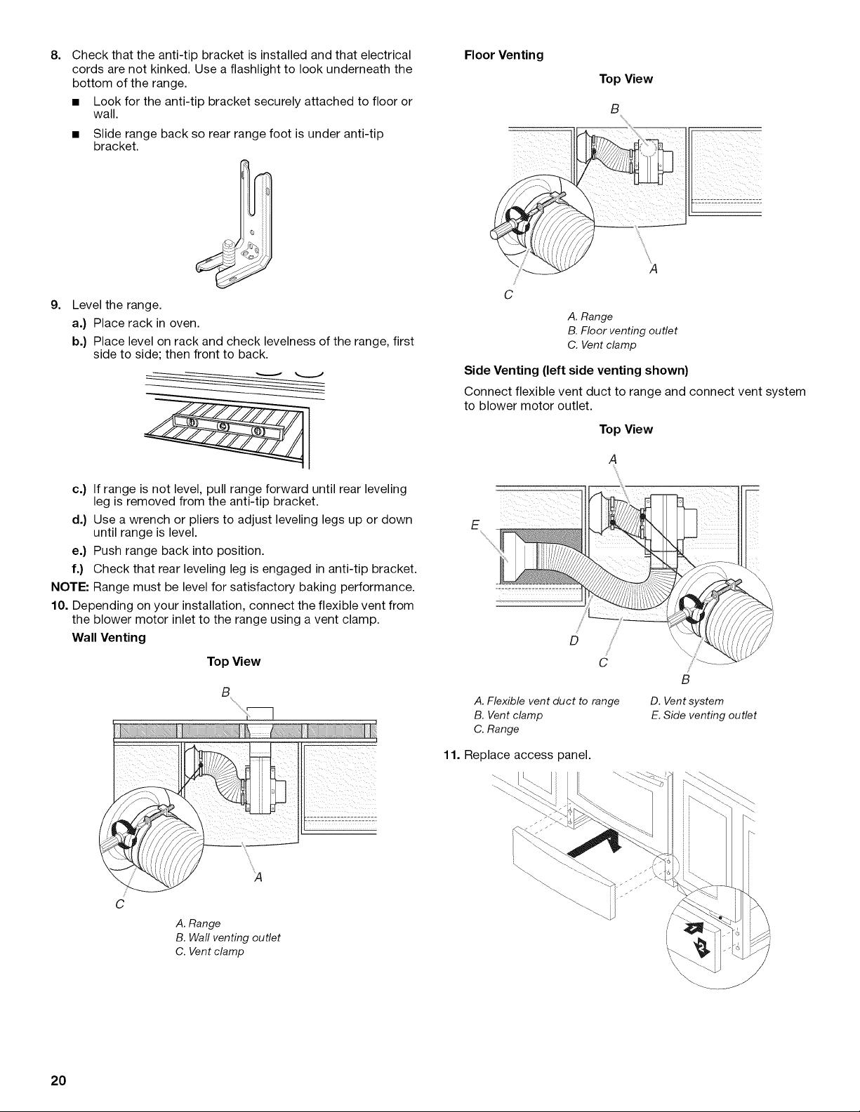
8. Floor Venting
Check that the anti-tip bracket is installed and that electrical
cords are not kinked. Use a flashlight to look underneath the
bottom of the range.
• Look for the anti-tip bracket securely attached to floor or
wall.
• Slide range back so rear range foot is under anti-tip
bracket.
g=
Level the range.
a.) Place rack in oven.
b.) Place level on rack and check levelness of the range, first
side to side; then front to back.
Side Venting (left side venting shown)
Connect flexible vent duct to range and connect vent system
to blower motor outlet.
Top View
A
A. Range
B. Floor venting outlet
C. Vent clamp
Top View
A
c.) If range is not level, pull range forward until rear leveling
leg is removed from the anti-tip bracket.
d.) Use a wrench or pliers to adjust leveling legs up or down
until range is level.
e.) Push range back into position.
f.) Check that rear leveling leg is engaged in anti-tip bracket.
NOTE: Range must be level for satisfactory baking performance.
10. Depending on your installation, connect the flexible vent from
the blower motor inlet to the range using a vent clamp.
Wall Venting
Top View
B
i ¸_ .... !
E
A. Flexible vent duct to range
B. Vent clamp
C. Range
11. Replace access panel.
C
/
B
D. Vent system
E. Side venting outlet
20
C,
A. Range
B. Wall venting outlet
C. Vent clamp
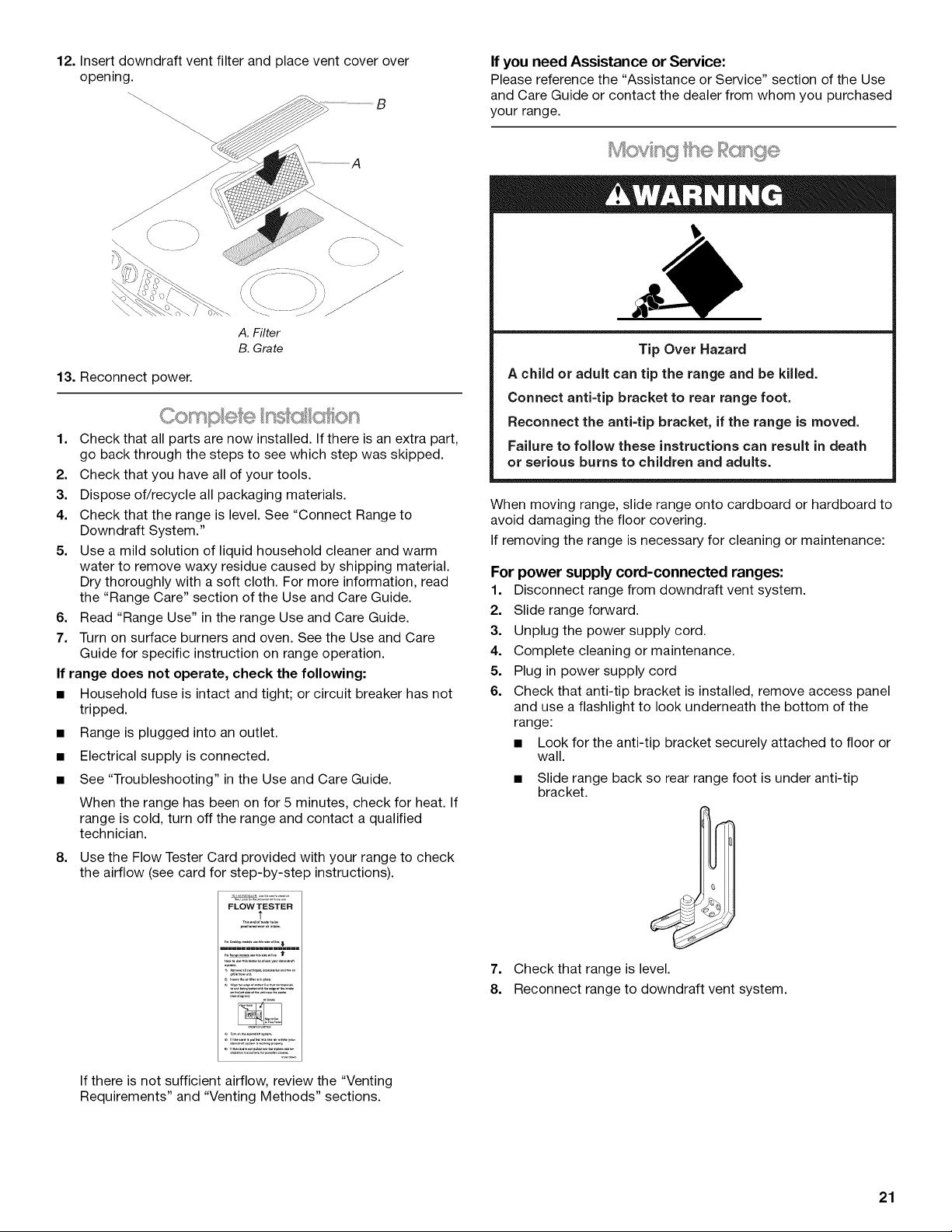
12. Insert downdraft vent filter and place vent cover over
opening.
B
A. Filter
B. Grate
13. Reconnect power.
1. Check that all parts are now installed. If there is an extra part,
go back through the steps to see which step was skipped.
2. Check that you have all of your tools.
3. Dispose of/recycle all packaging materials.
4. Check that the range is level. See "Connect Range to
Downdraft System."
5. Use a mild solution of liquid household cleaner and warm
water to remove waxy residue caused by shipping material.
Dry thoroughly with a soft cloth. For more information, read
the "Range Care" section of the Use and Care Guide.
6. Read "Range Use" in the range Use and Care Guide.
7. Turn on surface burners and oven. See the Use and Care
Guide for specific instruction on range operation.
If range does not operate, check the following:
• Household fuse is intact and tight; or circuit breaker has not
tripped.
• Range is plugged into an outlet.
• Electrical supply is connected.
• See "Troubleshooting" in the Use and Care Guide.
When the range has been on for 5 minutes, check for heat. If
range is cold, turn off the range and contact a qualified
technician.
8. Use the Flow Tester Card provided with your range to check
the airflow (see card for step-by-step instructions).
If you need Assistance or Service:
Please reference the "Assistance or Service" section of the Use
and Care Guide or contact the dealer from whom you purchased
your range.
Tip Over Hazard
A chi(d or adult can tip the range and be killed.
Connect anti=tip bracket to rear range foot.
Reconnect the anti=tip bracket, if the range is moved.
Failure to follow these instructions can result in death
or serious burns to children and adults.
When moving range, slide range onto cardboard or hardboard to
avoid damaging the floor covering.
If removing the range is necessary for cleaning or maintenance:
For power supply cord-connected ranges:
1. Disconnect range from downdraft vent system.
2. Slide range forward.
3. Unplug the power supply cord.
4. Complete cleaning or maintenance.
5. Plug in power supply cord
6. Check that anti-tip bracket is installed, remove access panel
and use a flashlight to look underneath the bottom of the
range:
• Look for the anti-tip bracket securely attached to floor or
wall.
• Slide range back so rear range foot is under anti-tip
bracket.
FLOW TESTER
::;.j2£;?-?/:??72::o::......
,=,,.................. _.......
If there is not sufficient airflow, review the "Venting
Requirements" and "Venting Methods" sections.
7. Check that range is level.
8. Reconnect range to downdraft vent system.
21
For direct-wired ranges:
Electrical Shock Hazard
Disconnect power before servicing.
Replace all parts and panels before operating.
Failure to do so can result in death or electrical shock.
1. Disconnect power.
2. Disconnect range from downdraft vent system.
3. Slide range forward.
4.
Complete cleaning or maintenance.
5.
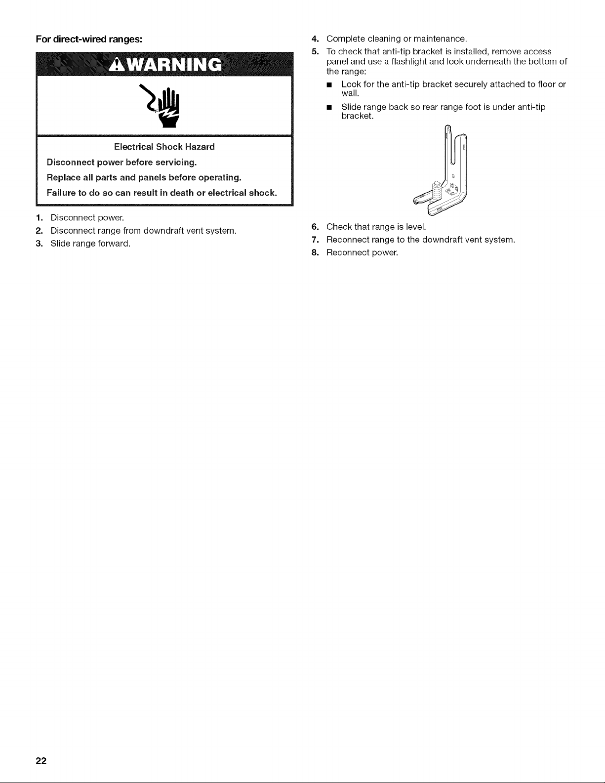
To check that anti-tip bracket is installed, remove access
panel and use a flashlight and look underneath the bottom of
the range:
• Look for the anti-tip bracket securely attached to floor or
wall.
• Slide range back so rear range foot is under anti-tip
bracket.
6. Check that range is level.
7. Reconnect range to the downdraft vent system.
8. Reconnect power.
22
SECURITEDELACUISINIERE
Votre securite et celle des autres est tres importante.
Nous donnons de nombreux messages de s_curit_ importants dans ce manuel et sur votre appareil m_nager. Assurez-vous de
toujours lire tousles messages de s_curit_ et de vous y conformer.
Ce symbole d'alerte de s_curit_ vous signale les dangers potentiels de d_c_s et de blessures graves & vous
et & d'autres.
Voici le symbole d'alerte de s_curit&
Tousles messages de s_curit_ suivront le symbole d'alerte de s_curit_ et le mot "DANGER" ou
"AVERTISSEMENT". Ces mots signifient •
Risque possible de d_cbs ou de blessure grave si vous ne
suivez pas imm_diatement les instructions.
Risque possible de d_cbs ou de blessure grave si vous
ne suivez pas les instructions.
Tous les messages de s_curit_ vous diront quel est le danger potentiel et vous disent comment r_duire le risque de blessure et
ce qui peut se produire en cas de non-respect des instructions.
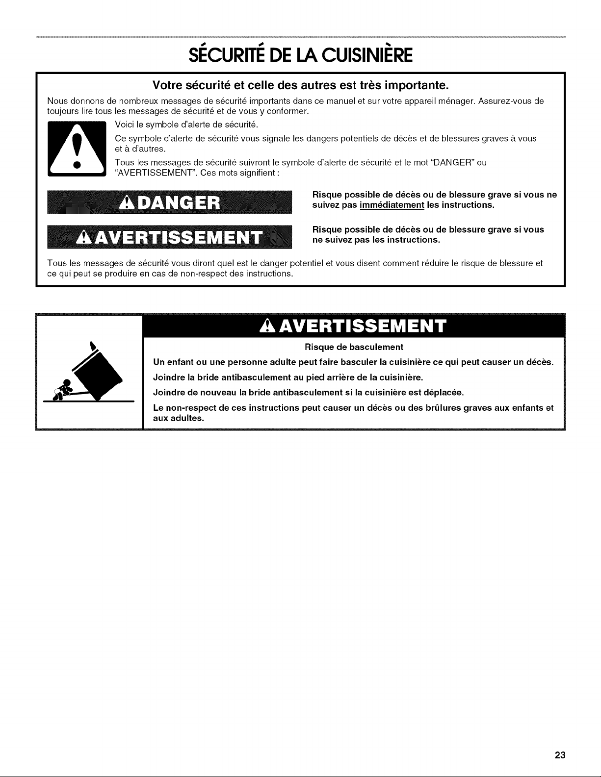
Risque de basculement
Un enfant ou une personne adulte peut faire basculer la cuisiniere ce qui peut causer un d_ces.
Joindre la bride antibasculement au pied arriere de la cuisiniere.
Joindre de nouveau la bride antibasculement si la cuisiniere est d_plac_e.
Le non-respect de ces instructions peut causer un d_ces ou des brl)lures graves aux enfants et
aux adultes.
23
EXIGENCESD'INSTALLATION
Rassembler les outils et composants nicessaires avant
d'entreprendre I'installation. Lire et observer les instructions
fournies avec chacun des outils de la liste ci-dessous.
Outils n_cessaires
• Metre-ruban
• Niveau
• Tournevis Phillips
• Tournevis a lame plate
• Scie sauteuse ou scie
guichet
• Marqueur ou crayon
Pi6ces fournies
Verifier que toutes les pieces sont presentes.
3 ecrous hexagonaux de #10-32 (visses au boiler de
connexion)
• 3 attaches de bornes
• 2 ou 3 grilles de four (en fonction du modele)
• Moteur du ventilateur
• 2 brides pour conduit
• Conduit flexible
• Fiche de test du debit
• Gabarit pour I'emplacement du ventilateur
• 4 vis n° 8 x %" (pour le montage de la bride du ventilateur)
• 2 vis n° 12 x 13/8"(pour le montage de la bride
antibasculement)
• Bride antibasculement (fixee par du ruban adhesif & la
pochette contenant la documentation dans la cavite du four)
La bride antibasculement doit _tre bien fixee & la cloison
arriere ou au plancher. La profondeur du plancher peut
necessiter des vis plus Iongues pour I'ancrage de la bride
dans le sous-plancher. Des vis plus Iongues sont disponibles
aupres de votre quincaillerie locale.
Pi_ces n_cessaires
• L'une des bouches de decharge murales Jenn-Air suivantes :
Clapet de decharge mural en surface rond Jenn-Air ®de
5" (12,7 cm). Commander la piece n°A405.
Clapet de decharge mural en surface rond Jenn-Air ®de
6" (15,2 cm). Commander la piece n°A406.
Clapet de decharge mural en surface Jenn-Air ®31¼'' x 10"
(8,3 x 25,4 cm). Commander la piece n° A403.
Pour commander, voir la section "Assistance ou service" du
Guide d'utilisation et d'entretien.
• Conduit metallique
• Brides pour conduit
• Chevilles a beton (pour montage sur sol en beton)
• 2 cales en bois 2" x 4" x 83_'' (5 x 10,2 x 22,2 cm) (pour
evacuation par la gauche ou par la droite)
• Cle ou pince
• Tourne-ecrou de ¾e"
• Tourne-ecrou de 1¼,,
• Perceuse
• Foret de 1/8"(3,2 mm)
• Foret & ma£:onnerie & pointe
carburee de ¾e" (4,8 mm)
(pour planchers en beton/
ceramique)
En cas d'utilisation d'un cordon d'alimentation _lectrique :
• Cordon d'alimentation (homologation UL) con£:u pour
I'utilisation avec une cuisiniere. Pour service 250 volts
minimum, 40 A ou 50 A, compatible avec une ouverture de
diametre nominal 13/8'' (3,5 cm) pour le raccordement, et avec
cosses rondes ou en fourche a pointes relevees a I'extremite
de chaque conducteur.
• Un serre-c&ble (homologation UL).
Consulter les codes Iocaux. Verifier I'alimentation electrique
existante. Voir la section "Specifications electriques".
II est recommande de faire realiser tousles raccordements
electriques par un electricien qualifie agree.
IMPORTANT : Observer les dispositions de tousles codes et
reglements en vigueur.
• C'est a I'installateur qu'incombe la responsabilite de
respecter les distances de separation exigees, specifiees sur
la plaque signaletique de I'appareil. La plaque signaletique
est situee sur le c6te droit du ch&ssis du four, derriere le
panneau du tiroir de remisage.
• La cuisiniere doit _tre installee a un endroit pratique dans la
cuisine.
• Afin de supprimer le risque de brQlures ou d'incendie lie au
fait de se pencher au-dessus des plaques de cuisson
chaudes, les meubles de rangement au-dessus des plaques
doivent _tre evites. Si des placards de rangement sont
envisages, le risque peut _tre reduit par I'installation d'une
hotte de cuisine depassant le bas des placards d'au moins 5"
(12,7 cm) horizontalement.
• Respecter les dimensions indiquees pour les ouvertures
decouper dans les placards. Ces dimensions constituent les
valeurs minimales des degagements.
• La bride antibasculement de plancher doit _tre installee. Pour
I'installation de la bride antibasculement fournie avec la
cuisiniere, voir la section "Installation de la bride
antibasculement".
• Une source d'electricite avec liaison & la terre est necessaire.
Voir la section "Specifications electriques".
IMPORTANT : Afin d'eviter d'endommager les placards,
consulter le constructeur de la maison ou le fabricant des
placards pour determiner si les materiaux utilises peuvent subir
un changement de couleur, une destratification ou d'autres
dommages. Ce four a ete con(;u conformement aux exigences
des normes UL et CSA International et respecte les temperatures
maximales permises de 194°F (90°C) pour les placards en bois.
R_sidence mobile - Specifications additionnelles
respecter Iors de I'installation
L'installation de cette cuisiniere doit _tre conforme aux
dispositions de la norme Manufactured Home Construction and
Safety Standard, Title 24 CFR, Part 3280 (anciennement Federal
Standard for Mobile Home Construction and Safety, Title 24,
HUD Part 280). Lorsque cette norme n'est pas applicable,
I'installation doit satisfaire aux criteres de la norme Standard for
Manufactured Home Installations, ANSI A225.1/NFPA 501A ou
aux dispositions des codes Iocaux.
24
 Loading...