

JENN-AIR JES9800ACW, JES9800ACS, JES9800ACB, JES9750AAS, JES9750AAB Installation Instructions
...
INSTALLER: LEAVE THESE INSTRUCTIONS WITH THE APPLIANCE
INSTALLATION MANUAL
Electric 30-inch Wide
Jenn-Air Downdraft Range
PLEASE KEEP THIS MANUAL FOR FUTURE REFERENCE
THE MANUAL IS INTENDED TO ASSIST IN THE INITIAL INSTALLATION AND ADJUSTMENTS OF THE RANGE.
SPECIAL WARNING
Only qualified personnel should
install or service this range.
Read “Safety Instructions” in Use &
Care book before using range.
Improper installation, adjustment,
alteration, service, maintenance or
use of range can result in serious
injury or property damage.
· ALL RANGES CAN TIP AND
CAUSE INJURIES TO PERSONS.
CLEARANCE DIMENSIONS
For complete information in regard to installation of
Jenn-Air range, see figures 1, 2, 3 and 4. For SAFETY
CONSIDERATIONS, do not install a range in any
combustible cabinetry which is not in accord with the
installation clearances shown in figure 1.
CAUTION: This range has been designed in
accordance with the requirements of various safety
agencies and complies with the maximum allowable
wood cabinet temperatures of 194°F. If this range
is installed with cabinets that have a lower working
temperature than 194°F, discoloration, delamination
or melting may occur.
Your range may not be equipped
with some of the features referred
to in this manual.
· INSTALL ANTI-TIP DEVICES
PACKED WITH RANGE.
· FOLLOW ALL INSTALLATION
INSTRUCTIONS.
ENGLISH '''' PP. 1-11
ESPAÑOL '''' pág. 12-22
FRANCAIS '''' p. 23-33
8101P427-60
(03-02-02)

INSTALLATION DRAWINGS (Pages 2, 3 & 4)
IMPORTANT
PLEASE KEEP FOR THE USE OF THE LOCAL ELECTRICAL INSPECTOR.
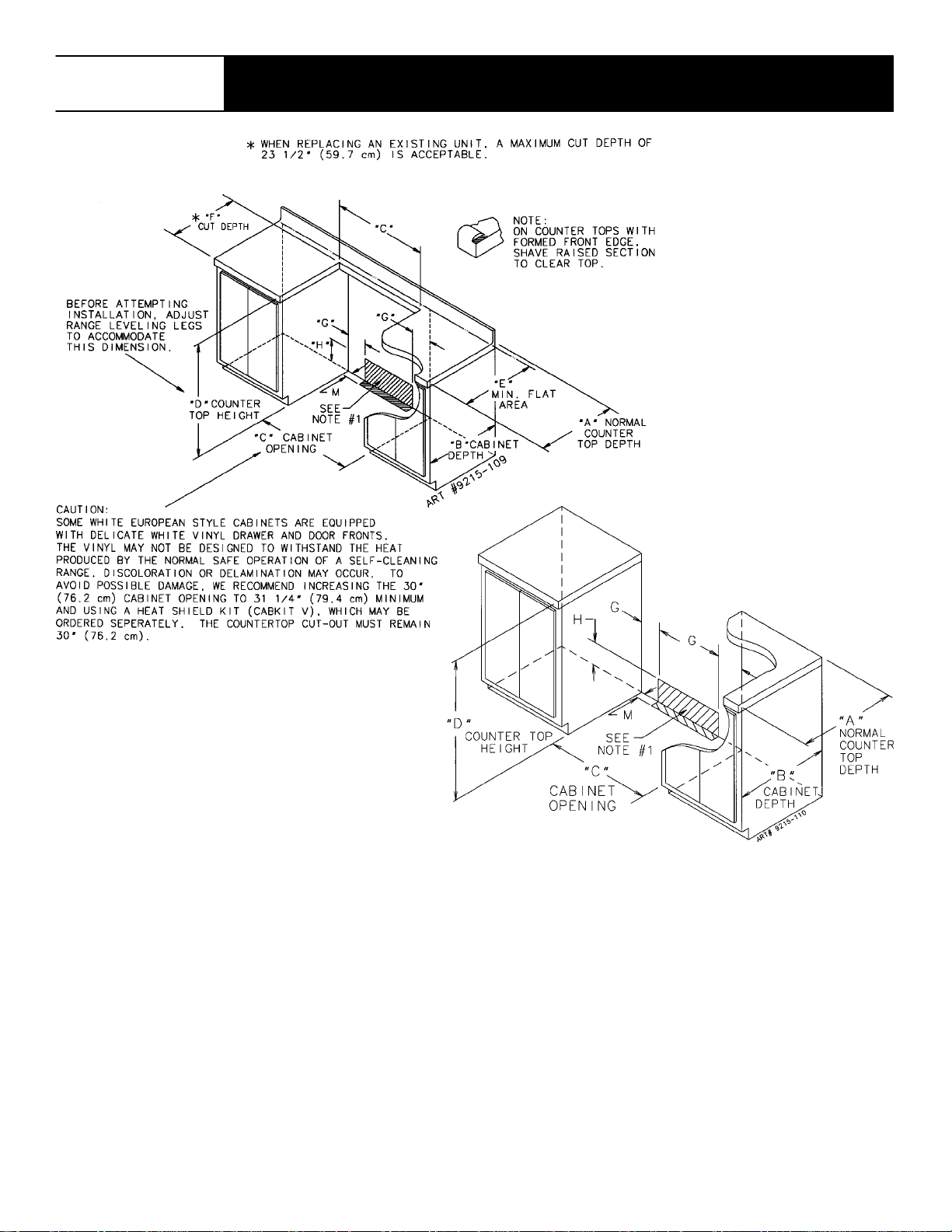
FIGURE 1
NOTE: Figure may not be representative of actual unit.
The 30 inches (76.2 cm) minimum clearance between the
top of the cooking surface and the bottom of an
unprotected wood or metal cabinet can be reduced to 24
inches (61 cm) minimum when bottom of wood or metal
cabinet is protected by not less than 1/4-inch (6.4 mm)
thick flame-retardant millboard covered with not less than
No. 28 MSG sheet steel, 0.015-inch (0.381 mm) thick
stainless steel, 0.024-inch (0.610 mm) thick aluminum, or
0.020-inch (0.508 mm) thick copper.
To eliminate the risk of burns or fire by reaching over
heated surface units, cabinet storage space located
above the surface units should be avoided. If cabinet
storage is to be provided, the risk can be reduced by
installing a range hood that projects horizontally a
minimum of 5 inches (13 cm) beyond the bottom of the
cabinets.
FIGURE 1
1 COMBUSTIBLE BACK WALL....
2 COMBUSTIBLE SIDE WALL....
3 COMBUSTIBLE WALL CABINET....
DIMENSION “A” IS TO BE A MINIMUM OF3INCHES (7.5
CM).
A SLIDE-IN RANGE, IF EQUIPPED WITH OPTIONAL
BACKGUARD KIT, MAY BE INSTALLED ZERO INCHES
FROM COMBUSTIBLE WALL 1 (SEE FIGURE 1).
-2-
30²
²
²²
JENN-AIR RANGES
FIGURE 2
FIGURE 3
NOTES:
1. Provide for either a 3-wire or 4 -wire 120/208, 120/240 volt outlet per applicable cord in shaded area shown. Refer
to installation instructions for proper positioning of outlet.
2. Dimension K (figure 4, page 4) is from the wall to the side edge of the oven door.Itdoes not include the curvature
of the glass or the depth of the handle.
3. Dimension L (figure 4, page 4) is with the leveler legs adjusted all the wayin. This may vary slightly upon leveling
leg adjustment.
4. Do not use grout, epoxy, etc., to install this unit. Installation must allow for removal of this appliance from t he
installed location for purposes of servicing.
-3-

30²
²
²²
JENN-AIR RANGES
Slide-In Range
Dimensions
FIGURE 4
JJJJ
A
B
C
D
E
F
G
H
J
2*
K
3*
L
M
* SEE NOTES ON PAGE 3
Inches
25
24
30
36
23 5/8
23 1/4
51/2
10
29 7/8
26 3/16
35 3/4
2/1/4
Centimeters
63.5
61.0
76.2
91.4
60.0
59.1
14.0
25.4
75.9
66.5
90.8
5.7
-4-
MOBILE HOMES
LOCATING THE RANGE
The installation of a range designed for mobile home
installation must conform with the Manufactured Home
Construction and Safety Standard, Title 24 CFR, Part
3280 (formerly the Federal Standard for Mobile Home
Construction and Safety, Title 24 HUD, Part 280) or,
when such standard is not applicable, the Standard for
Manufactured Home Installations 1982 (Manufactured
Home Sites, Communities and Set-Ups), ANSI
A225.1-latest edition, or with local codes.
Place range in a well lit area. Do not set range over holes
in the floor or other locations where it may be subject to
strong drafts. Any opening in the wall behind the range
and in the floor under the range should be sealed. Make
sure the flow of cooling/ventilation air is not obstructed
below the range.
NOTE: A range should NOT be installed over kitchen
carpeting.
ANTI-TIP DEVICE INSTALLATION INSTRUCTIONS
WARNING: A risk of range tip-over exists if the
appliance is not installed in accordance with the provided
installation instructions. The proper use of this device
minimizes the risk of TIP-OVER. In using this device the
consumer must still observe the safety precautions as
stated in the USE and CARE MANUAL and avoid using
the oven doors as a step stool.
Installation instructions are provided for wood and cement
in either floor or wall. Any other type of construction may
require special installation techniques as deemed
necessary to provide adequate fastening of the ANTI-TIP
bracket to the floor or wall. The bracket may be installed
to engage the LEFT or RIGHT rear leveling foot.
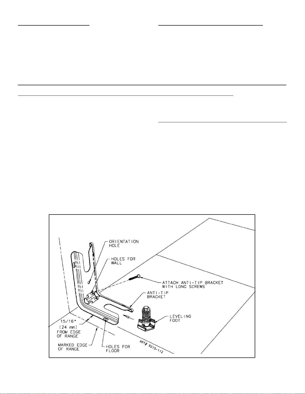
Install the bracket with the orientation hole in the longer
leg against the wall as shown in figure 5.
STEP 1 - Locating The Anti-tip Bracket (See Figure
A. Determine where either the right or left “EDGE” of the
range will be located and mark the floor or wall.
B. Place the BRACKET 15/16² (24mm) from the marked
“EDGE” toward center of opening and against the
back wall as shown in figure 5, with orientation hole
against wall.
C. Use the bracket as a template and mark the required
holes, as shown in figure 5, for the type of
construction you will be using.
5)
NOTE: The bracket provided is designed for use with
flush mount and non-flush mount outlet receptacles.
D. Anti-tip bracket may be secured to either floor or wall.
See Step 2 on page 6 for bracket installation options.
FIGURE 5
-5-
STEP 2 - Anti-Tip Bracket Installation
A. Wood Construction:
1. Floor: Locate the center of the two holes identified
in figure 5 as “HOLES FOR FLOOR.” Drill a 1/8²
(3 mm) pilot hole in the center of each hole (a nail
or awl may be used if a drill is not available).
Secure the ANTI-TIP bracket to the floor with the
two screws provided. Proceed to STEP 3.
2. Wall: Locate the center of the two holes identified
in figure 5 as “HOLES FOR WALL.” Drill an
angled 1/8² (3 mm) pilot hole in the center of each
hole as shown in figure 6. (A nail or awl may be
used if a drill is not available). Secure the
ANTI-TIP bracket to the wall with the two screws
provided as shown in figure 6. Proceed to STEP
3.
B. Cement or Concrete Construction:
1. Suitable screws for concrete construction can be
obtained at the hardware store. Drill the required
size hole for the hardware obtained into the
concrete at the center of the holes identified in
figure5 as “HOLES FOR FLOOR”. Secure the
ANTI-TIP bracket to the floor. Proceed to STEP 3.
Options
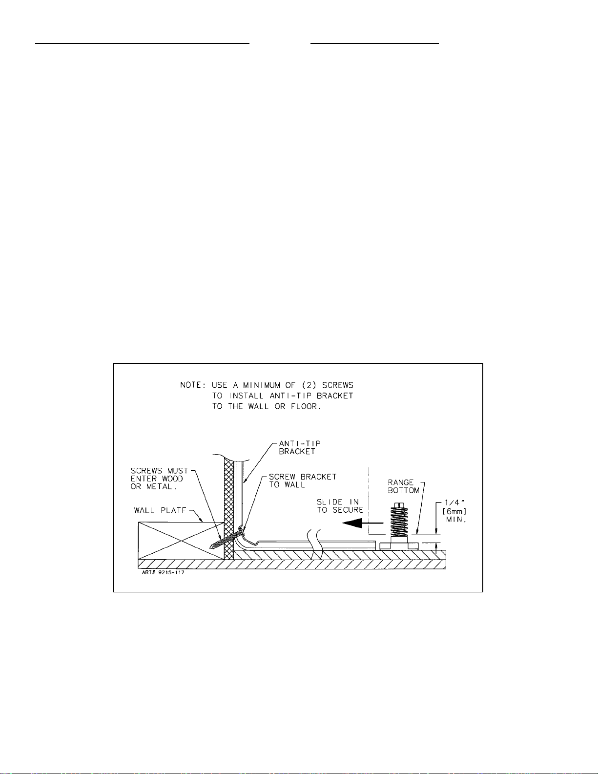
STEP 3 - Range
A. A Jenn-Air range may be installed by one person.
B. Align the range to its designated location and slide it
back into position. Note: A minimum clearance of 1/4²
(6 mm) is required between the range and the leveling
foot that will engage the ANTI-TIP bracket, see figure
6.
C. All Jenn-Air ranges have a non lift-up top.
D. For SAFETY CONSIDERATIONS as well as optimum
performance adjust the range so that it is level. This
may be checked by placing a spirit level or a large
pan of water on the cooktop or the oven rack. If an
adjustment is required pull the range forward, tip the
range and rotate the leveling feet as required.
E. To check the range for proper installation of the
anti-tip bracket: Use a flashlight and look underneath
the bottom of the range to see that one of the rear
leveling feet is engaged in the bracket slot.
F. Proceed with the remainder of the installation
instructions provided with the range.
Installation
FIGURE 6
-6-

CONNECTING THE RANGE
ELECTRIC SUPPLY
The range must be installed in accordance with Local and
National Electric Code (NEC) ANSI/NFPA No. 70-latest
edition. See rating plate for total connected KW rating.
ELECTRIC SUPPLY (Canada)
The range must be installed in accordance with Local and
Canadian Electric Code CSA STD.C22.1 latest edition.
See rating plate for total connected KW rating.
OUTSIDE WIRING
Your local utility company will tell you whether the present
electric service to your home is adequate. It may be
necessary to increase the size of the wiring to the house
and service switch to take care of the electrical load
demanded by the range. The kilowatt rating for the range
is specified on the rating plate located on the front of the
range.
HOUSE WIRING
Most local Building Regulations and Codes require that all
electrical wiring be done by licensed electricians. All
wiring should conform to Local and National Electrical
Codes. This range requires a single phase three wire
120/240 or a 120/208 volt, 60 Hz, AC circuit. Wiring codes
require a separate circuit be run from the main entrance
panel to the range and that it be equipped with separate
disconnect switch and fuses, either in the main entrance
panel or in a separate switch and fuse box. In some
communities, a solid or flexible continuous armored
conduit must be used from main entrance panel to the
terminal box on the rear of the range. Others will permit
the termination of the range circuit at a polarized three or
four wire plug-in outlet placed at a convenient point near
the back of the range. The range is then connected to this
outlet through an approved range connector (pigtail)
fastened securely to the terminal block with proper strain
relief at the range and a three or four pronged plug at the
opposite end.
RANGE CONNECTIONS
Some models are shipped direct from the factory with
service cords (pigtails) attached. There are no range
connections necessary on these models. Just plug into
the range outlet. On models not provided with a service
cord, connection to the power supply is necessary.
REMEMBER - only a 4-conductor cord is to be used on
new branch-circuit installations (1996 NEC), mobile
homes, recreational vehicles, or in an area where local
codes prohibit grounding through the neutral conductor.
Hence, 4-wire service MUST be provided for such
installations. 3-wire service may be used when permitted
by local code. USE COPPER OR ALUMINUM
CONDUCTORS. Main terminal block is recognized for
Copper or Aluminum conductors. If a flexible power cord
is required, it is recommended a cord no longer than 4 ft.
be used. Make connections as explained below and with
reference to the appropriate illustration (see figures 8 and
9). After installation, insure tightness of all electrical
connections and replace all covers.
Remove terminal block access cover from range back.
(See figure 7).
RANGE CONNECTIONS (Canada)
This model was shipped direct from the factory with
service cord (pigtail) attached. There are no range
connections necessary. Just plug into the range outlet.
See figure 2 on page 3 for outlet location.
NOTE: Cord replacement - ONLY a power supply cord
rated at 240 volts minimum, 40 amperes or 50 amperes
power supply cord that is marked for use with nominal
13/8² (34.93 mm) diameter connection opening, with
closed loop terminals and marked for use with ranges
shall be used.
-7-
FIGURE 7

3-WIRE SERVICE CORD OR CONDUIT
INSTALLATION
1. Insure that the copper ground strap IS CONNECTED
between the middle post of the main terminal
connection block and the range chassis.
2. The middle wire of the service cord or ground lead of
3-wire conduit MUST connect to the neutral (middle)
post of the main terminal block. The other two wires of
the service cord or conduit connect to the outside
posts of the main terminal connection block. Polarity is
unimportant.
3. A appropriate strain relief for service cord or conduit
must be attached to the conduit plate.
4-WIRE SERVICE CORD OR CONDUIT
INSTALLATION
(MOBILE HOMES OR AS REQUIRED BY CODES)
1. The copper ground strap connected between the
neutral (middle) post of the main terminal block and the
chassis MUST be cut off as shown in figure 9. Save the
green ground screw to attach the ground from the 4
wire cord. Only a 4 wire cord or conduit should be
used.
2. The ground wire from the service cord or conduit must
connect to the range chassis using the green ground
screw.
3. The white wire of the service cord or conduit must
connect to the neutral (middle) post of the main
terminal block. The other two wires of the service cord
or conduit connect to the red and black posts of the
main terminal block, respectively.
4. An appropriate strain relief for service cord or conduit
must be attached to the conduit plate.
CONVERSION FROM 3-WIRE TO 4-WIRE
SERVICE
(Model With 3-Wire Service Cord Attached)
Disconnect range from power. Remove the access cover
on back of range and remove the 3-wire service cord from
the main terminal block. Follow instructions as outlined in
figure 9 to connect the 4-wire service cord.
FIGURE 8
ACCEPTABLE 3-WIRE PLUG INSTALLATION
NOTE: Cord replacement - ONLY a power supply cord
rated at 240 volts minimum, 40 amperes or 50 amperes
power supply cord that is marked for use with nominal
13/8² (34.93 mm) diameter connection opening, with
closed loop terminals and marked for use with ranges
shall be used.
FIGURE 9
ACCEPTABLE 4-WIRE PLUG INSTALLATION
-8-

DOWNDRAFT INSTALLATION INSTRUCTIONS
S Determine where you will be locating the electrical
outlet. It must be in the floor or on the wall within the
area shown in figure 2 or 3.
S Determine how you will be venting your downdraft
blower. You may vent through the rear wall, the floor,
or the sides. When locating the downdraft vent
opening make sure it will not interfere with your
electrical outlet.
a. Through the rear wall. (See figure 10) Mark the
centerline of the cabinet opening on the rear wall.
The61/4² vent opening must be located on a
centerline 8 3/8² above the floor and within 3 1/4²
to the right (when facing the cabinet opening) of
the centerline of the cabinet opening as shown in
figure 10.
Cuta61/4² diameter hole on the marked
centerline making sure to miss any wall studs.
Install the blower as shown in figure 12.
Figure 10
b. Through the floor. (See figure 11) Making sure to
miss any floor joists cut a 6 1/4² diameter hole in
the shaded area as shown in figure 11. Install the
blower as shown in figure 12.
NOTE: If the floor is a concrete slab, see
the enclosed ducting instructions.
c. Through the Left or Right side cabinet.
(See figure 13).
1. Additional materials required:
1pc5² diameter x 19² long (12.7 cm x 48.26
cm).
Flex duct (P/N 702935).
1pc6² (15.25 cm) 90_ elbow.
2 Hose Clamps (P/N 702331).
1pc5² to31/4² x10² (12.7cmto8.26cmx
25.4 cm) Transition.
2 pcs Wood spacers (right side vent only)
11/2² thickx9² long (3.81 cm x 22.68 cm).
Figure 11
Figure 12
(See your local dealer for these accessories).
2. Cut hole in either the left or right side of the
cabinet wall as shown in figure 13.
3. Make cutout in the cabinet floor of either the right
or left side cabinet as shown in figures 14 or 15.
4. Relocate the mounting brackets on the blower
housing as shown in figure 17.
Figure 13
-9-
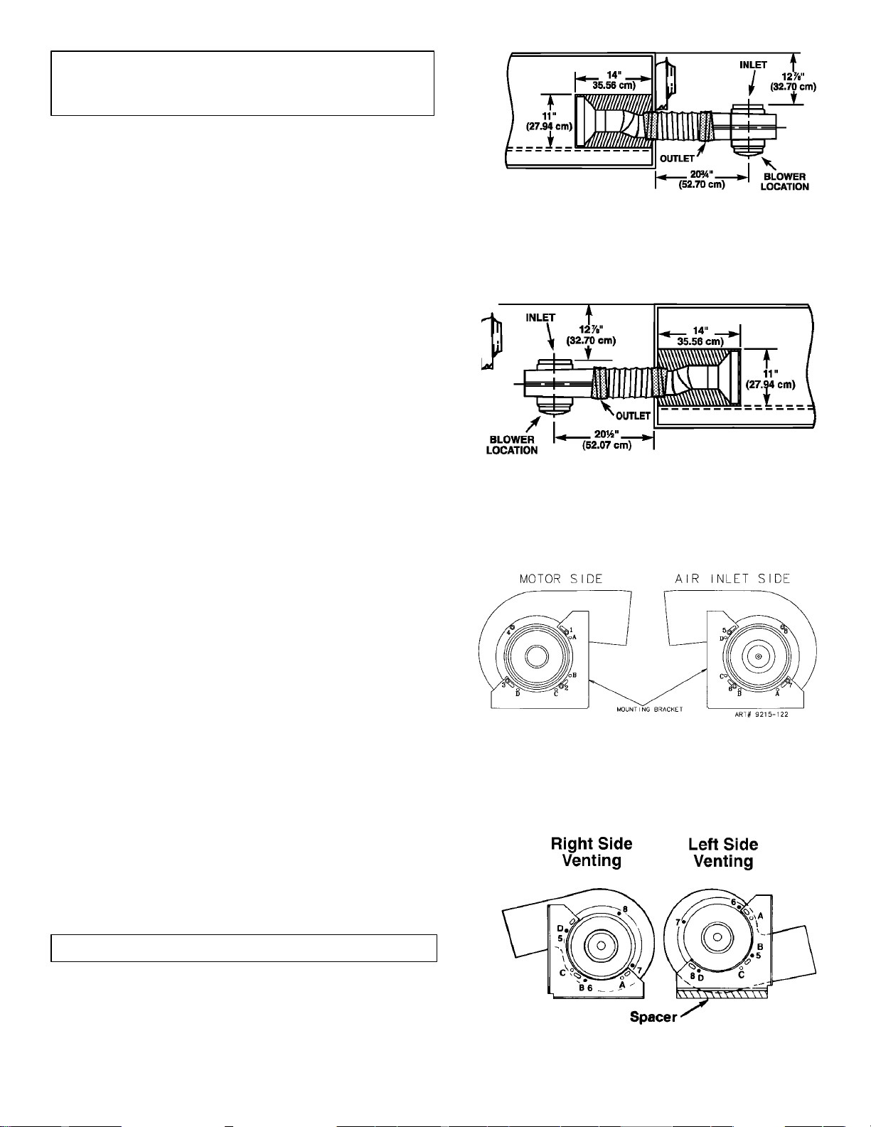
NOTE: The mounting brackets shown in figure 16
are as assembled at the factory for floor or rear wall
venting.
a. Right side venting (figure 17).
1. Remove nuts from studs 1, 2 and 3 on the motor
side.
2. Remove bracket and reattach with studs 1 and 2
inserted in holes A and C and replace 3 nuts.
3. Remove nuts from studs 5, 6 and 7 on air inlet side.
4. Remove bracket and reattach with studs 5 and 6
inserted in holes D and B and replace 3 nuts.
b. Left side venting (figure 17).
1. Remove nuts from studs 1, 2, 3 and 4 on motor
side.
2. Remove bracket.
3. Rotate motor and cover assembly 180 degrees.
4. Reattach bracket with studs 4 and 1 inserted in
holes A and C and replace all 4 nuts.
5. Remove nuts from studs 5, 6, 7 and 8 on inlet side.
6. Remove bracket and reattach with studs 8 and 5
inserted in holes D and B and replace all 4 nuts.
5. Attach the blower housing to the floor with the outlet
towards the direction of the venting and the inlet towards
the front of the cabinets. In addition, for left side venting, a
spacer of approximately 1-1/2² thickx9² long (3.81 cm x
22.86 cm) is required under the mounting bracket flanges
of the blower assembly (see figure 17).
6. Remove the inside wire and outside string from the first
1-1/2² (3.81 cm) of one end of the 5² (12.7 cm) flex duct
(P/N 702935). Stretch this end of the flex duct over the
end of the 5² x3-1/4² x10² (12.7 cm x 25.4 cm) transition
and secure with hose clamp (P/N 702331).
7. When the range is placed in position, feed the open end of
the 5² (12.7 cm) flex duct through the hole in the cabinet
side wall and attach to the outlet of the blower housing
with hose clamp (P/N 702331). The transition should then
be attached to the 3-1/4² x10² (12.7 cm x 25.4 cm)
ducting in the cabinet toe space through the cabinet floor
cutout.
8. Install the 6² (15.24 cm) elbow of the blower housing and
secure with duct tape. The open end of the elbow should
be pointed to the left. Attach the 6² (15.24 cm) flex duct
(provided with the range) to the elbow and to the range.
Note: For right side venting, the 6² (15.24 cm) diameter
flex duct may be cut in half and used in order to make
assembly easier.
Figure 14
Left Cabinet (Top View)
Figure 15
Right Cabinet (Top View)
Figure 16
Blower Assembly
INSTALLING THE BLOWER
NOTE: Install the blower prior to installing the range.
S Refer to your duct plan. It may be easier to attach part of
the ducting to the blower before it is installed.
S Position the blower and attach to the floor with at least 2
screws.
S Apply duct tape to blower exhaust duct joint. (See figure
12).
Figure 17
View from Air Inlet Side of Blower
-10-
 Loading...