

JENN-AIR JES8850ACW, JES8850ACS, JES8850ACB, JES8750AAW, JES8750AAB Installation Instructions
...Page 1

INSTALLER: LEAVE THESE INSTRUCTIONS WITH THE APPLIANCE
INSTALLATION MANUAL
Electric 30-inch Wide
Jenn-Air Radiant Element Range
PLEASE KEEP THIS MANUAL FOR FUTURE REFERENCE
THE MANUAL IS INTENDED TO ASSIST IN THE INITIAL INSTALLATION AND ADJUSTMENTS OF THE RANGE.
SPECIAL WARNING
Only qualified personnel should
install or service this range.
Read “Safety Instructions” in Use &
Care book before using range.
Improper installation, adjustment,
alteration, service, maintenance or
use of range can result in serious
injury or property damage.
· ALL RANGES CAN TIP AND
CAUSE INJURIES TO PERSONS.
CLEARANCE DIMENSIONS
For complete information in regard to installation of
Jenn-Air range, see figures 1, 2, 3 and 4. For SAFETY
CONSIDERATIONS, do not install a range in any
combustible cabinetry which is not in accord with the
installation clearances shown in figure 1.
CAUTION: This range has been designed in
accordance with the requirements of various safety
agencies and complies with the maximum allowable
wood cabinet temperatures of 194°F. If this range
is installed with cabinets that have a lower working
temperature than 194°F, discoloration, delamination
or melting may occur.
Your range may not be equipped
with some of the features referred
to in this manual.
· INSTALL ANTI-TIP DEVICES
PACKED WITH RANGE.
· FOLLOW ALL INSTALLATION
INSTRUCTIONS.
ENGLISH '''' PP. 1-8
ESPAÑOL '''' pág. 9-16
FRANCAIS '''' p. 17-24
8101P429-60
(03-02-01)
Page 2

INSTALLATION DRAWINGS (Pages 2, 3 & 4)
IMPORTANT
PLEASE KEEP FOR THE USE OF THE LOCAL ELECTRICAL INSPECTOR.
FIGURE 1
NOTE: Figure may not be representative of actual unit.
The 30 inches (76.2 cm) minimum clearance between the
top of the cooking surface and the bottom of an
unprotected wood or metal cabinet can be reduced to 24
inches (61 cm) minimum when bottom of wood or metal
cabinet is protected by not less than 1/4-inch (6.4 mm)
thick flame-retardant millboard covered with not less than
No. 28 MSG sheet steel, 0.015-inch (0.381 mm) thick
stainless steel, 0.024-inch (0.610 mm) thick aluminum, or
0.020-inch (0.508 mm) thick copper.
To eliminate the risk of burns or fire by reaching over
heated surface units, cabinet storage space located
above the surface units should be avoided. If cabinet
storage is to be provided, the risk can be reduced by
installing a range hood that projects horizontally a
minimum of 5 inches (13 cm) beyond the bottom of the
cabinets.
FIGURE 1
1 COMBUSTIBLE BACK WALL....
2 COMBUSTIBLE SIDE WALL....
3 COMBUSTIBLE WALL CABINET....
DIMENSION “A” ISTOBEA MINIMUM OF 3 INCHES (7.5
CM).
A SLIDE-IN RANGE, IF EQUIPPED WITH OPTIONAL
BACKGUARD KIT, MAY BE INSTALLED ZERO INCHES
FROM COMBUSTIBLE WALL 1 (SEE FIGURE 1).
-2-
Page 3

30²
²
²²
JENN-AIR RANGES
FIGURE 2
FIGURE 3
Notes:
1. Provide for either a 3-wire or 4-wire 120/208, 120/240 volt outlet per applicable cord in shaded area shown. Refer
to installation instructions for proper positioning of outlet.
2. Dimension K (figure 4, page 4) is from the wall to the side edge of the oven door. It does not include the curvature
of the glass or the depth of the handle.
3. Dimension L (figure 4, page 4) is with the leveler legs adjusted all the way in. This may vary slightly upon leveling
leg a djustment.
4. Do not use grout, epoxy, etc., to install this unit. Installation must allow for removal of this appliance from the
installed location for purposes of servicing.
-3-
Page 4

30²
²
²²
JENN-AIR RANGES
Unity II Slide-In Range
Dimensions
FIGURE 4
JJJJ
A
B
C
D
E
F
G
H
J
2*
K
3*
L
M
* SEE NOTES ON PAGE 3
Inches
25
24
30
36
23 5/8
23 1/4
51/2
10
29 7/8
26 3/16
35 3/4
2/1/4
Centimeters
63.5
61.0
76.2
91.4
60.0
59.1
14.0
25.4
75.9
66.5
90.8
5.7
-4-
Page 5

MOBILE HOMES
LOCATING THE RANGE
The installation of a range designed for mobile home
installation must conform with the Manufactured Home
Construction and Safety Standard, Title 24 CFR, Part
3280 (formerly the Federal Standard for Mobile Home
Construction and Safety, Title 24 HUD, Part 280) or,
when such standard is not applicable, the Standard for
Manufactured Home Installations 1982 (Manufactured
Home Sites, Communities and Set-Ups), ANSI
A225.1-latest edition, or with local codes.
Place range in a well lit area. Do not set range over holes
in the floor or other locations where it may be subject to
strong drafts. Any opening in the wall behind the range
and in the floor under the range should be sealed. Make
sure the flow of cooling/ventilation air is not obstructed
below the range.
NOTE: A range should NOT be installed over kitchen
carpeting.
ANTI-TIP DEVICE INSTALLATION INSTRUCTIONS
WARNING: A risk of range tip-over exists if the appliance
is not installed in accordance with the provided installation
instructions. The proper use of this device minimizes the
risk of TIP-OVER. In using this device the consumer must
still observe the safety precautions as stated in the USE
and CARE MANUAL and avoid using the oven doors as a
step stool.
Installation instructions are provided for wood and cement
in either floor or wall. Any other type of construction may
require special installation techniques as deemed
necessary to provide adequate fastening of the ANTI-TIP
bracket to the floor or wall. The bracket may be installed
to engage the LEFT or RIGHT rear leveling foot.
NOTE: The bracket provided is designed for use with
flush mount and non-flush mount outlet receptacles.
Install the bracket with the orientation hole in the longer
leg against the wall as shown in figure 5.
STEP 1 - Locating The Anti-tip Bracket (See Figure
A. Determine where either the right or left “EDGE” of the
range will be located and mark the floor or wall.
B. Place the BRACKET 15/16² (24mm) from the marked
“EDGE” toward center of opening and against the
back wall as shown in figure 5, with orientation hole
against wall.
C. Use the bracket as a template and mark the required
holes, as shown in figure 5, for the type of
construction you will be using.
D. Anti-tip bracket may be secured to either floor or wall.
See Step 2 on page 6 for bracket installation options.
5)
FIGURE 5
-5-
Page 6
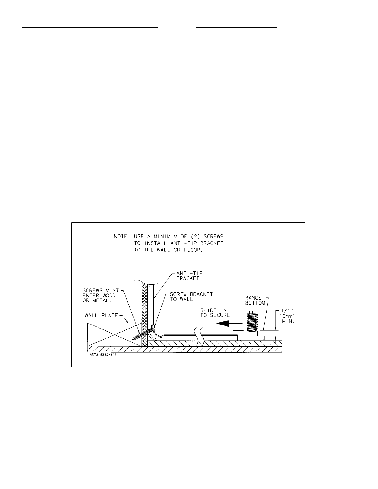
STEP 2 - Anti-Tip Bracket Installation
A. Wood Construction:
1. Floor:Locatethecenterofthetwoholesidentifiedin
figure 5 as “HOLES FOR FLOOR.” Drill a 1/8² (3
mm) pilot hole in the center of each hole (a nail or
awlmaybeusedifa drillisnotavailable).Securethe
ANTI-TIP bracket to the floor with the two screws
provided. Proceed to STEP 3.
Options
STEP 3 - Range
A. A Jenn-Air range may be installed by one person.
B. Align the range to its designated location and slide it
back into position. Note: A minimum clearance of 1/4²
(6 mm) is required between the range and the leveling
foot that will engage the ANTI-TIP bracket, see figure
6.
Installation
2. Wall:Locate the center of the two holes identified in
figure 5 as “HOLES FOR WALL.” Drill an angled
1/8² (3 mm) pilot hole in the center of each hole as
showninfigure 6. (A nailorawlmaybe used if adrill
isnotavailable).SecuretheANTI-TIPbracket tothe
wallwiththetwo screws provided as shown in figure
6. Proceed to STEP 3.
B. Cement or Concrete Construction:
1. Suitable screws for concrete construction can be
obtained at the hardware store. Drill the required
size hole for the hardware obtained into the
concreteatthecenteroftheholesidentifiedinfigure
5 as “HOLES FOR FLOOR”. Secure the ANTI-TIP
bracket to the floor. Proceed to STEP 3.
C. All Jenn-Air ranges have a non lift-up top.
D. For SAFETY CONSIDERATIONS as well as optimum
performance adjust the range so that it is level. This
may be checked by placing a spirit level or a large
pan of water on the cooktop or the oven rack. If an
adjustment is required pull the range forward, tip the
range and rotate the leveling feet as required.
E. To check the range for proper installation of the
anti-tip bracket: Use a flashlight and look underneath
the bottom of the range to see that one of the rear
leveling feet is engaged in the bracket slot.
F. Proceed with the remainder of the installation
instructions provided with the range.
FIGURE 6
-6-
Page 7
CONNECTING THE RANGE
ELECTRIC SUPPLY
The range must be installed in accordance with Local and
National Electric Code (NEC) ANSI/NFPA No. 70-latest
edition. See rating plate for total connected KW rating.
ELECTRIC SUPPLY (Canada)
The range must be installed in accordance with Local and
Canadian Electric Code CSA STD.C22.1 latest edition.
See rating plate for total connected KW rating.
OUTSIDE WIRING
Your local utility company will tell you whether the present
electric service to your home is adequate. It may be
necessary to increase the size of the wiring to the house
and service switch to take care of the electrical load
demanded by the range. The kilowatt rating for the range
is specified on the rating plate located on the front of the
range.
HOUSE WIRING
Most local Building Regulations and Codes require that all
electrical wiring be done by licensed electricians. All
wiring should conform to Local and National Electrical
Codes. This range requires a single phase three wire
120/240 or a 120/208 volt, 60 Hz, AC circuit. Wiring codes
require a separate circuit be run from the main entrance
panel to the range and that it be equipped with separate
disconnect switch and fuses, either in the main entrance
panel or in a separate switch and fuse box. In some
communities, a solid or flexible continuous armored
conduit must be used from main entrance panel to the
terminal box on the rear of the range. Others will permit
the termination of the range circuit at a polarized three or
four wire plug-in outlet placed at a convenient point near
the back of the range. The range is then connected to this
outlet through an approved range connector (pigtail)
fastened securely to the terminal block with proper strain
relief at the range and a three or four pronged plug at the
opposite end.
RANGE CONNECTIONS
Some models are shipped direct from the factory with
service cords (pigtails) attached. There are no range
connections necessary on these models. Just plug into
the range outlet. On models not provided with a service
cord, connection to the power supply is necessary.
REMEMBER - only a 4-conductor cord is to be used on
new branch-circuit installations (1996 NEC), mobile
homes, recreational vehicles, or in an area where local
codes prohibit grounding through the neutral conductor.
Hence, 4-wire service MUST be provided for such
installations. 3-wire service may be used when permitted
by local code. USE COPPER OR ALUMINUM
CONDUCTORS. Main terminal block is recognized for
Copper or Aluminum conductors. If a flexible power cord
is required, it is recommended a cord no longer than 4 ft.
be used. Make connections as explained below and with
reference to the appropriate illustration (see figures 8 and
9). After installation, insure tightness of all electrical
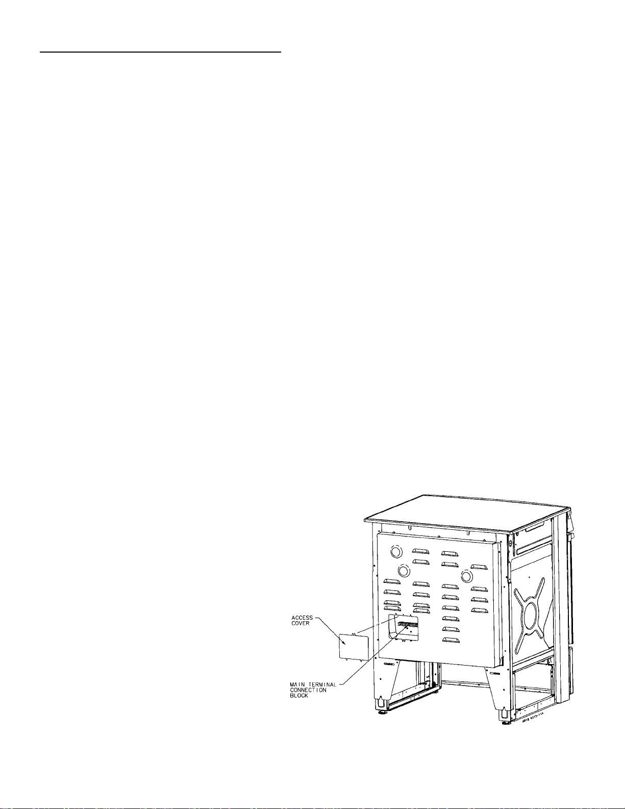
connections and replace all covers.
Remove terminal block access cover from range back.
(See figure 7).
RANGE CONNECTIONS (Canada)
This model was shipped direct from the factory with
service cord (pigtail) attached. There are no range
connections necessary. Just plug into the range outlet.
See figure 2 on page 3 for outlet location.
NOTE: Cord replacement - ONLY a power supply cord
rated at 240 volts minimum, 40 amperes or 50 amperes
power supply cord that is marked for use with nominal
13/8² (34.93 mm) diameter connection opening, with
closed loop terminals and marked for use with ranges
shall be used.
-7-
FIGURE 7
Page 8

3-WIRE SERVICE CORD OR CONDUIT
INSTALLATION
1. Insure that the copper ground strap IS CONNECTED
between the middle post of the main terminal
connection block and the range chassis.
2. The middle wire of the service cord or ground lead of
3-wire conduit MUST connect to the neutral (middle)
post of the main terminal block. The other two wires of
the service cord or conduit connect to the outside
posts of the main terminal connection block. Polarity is
unimportant.
3. A appropriate strain relief for service cord or conduit
must be attached to the conduit plate.
4-WIRE SERVICE CORD OR CONDUIT
INSTALLATION
(MOBILE HOMES OR AS REQUIRED BY CODES)
1. The copper ground strap connected between the
neutral (middle) post of the main terminal block and the
chassis MUST be cut off as shown in figure 9. Save the
green ground screw to attach the ground from the 4
wire cord. Only a 4 wire cord or conduit should be
used.
2. The ground wire from the service cord or conduit must
connect to the range chassis using the green ground
screw.
3. The white wire of the service cord or conduit must
connect to the neutral (middle) post of the main
terminal block. The other two wires of the service cord
or conduit connect to the red and black posts of the
main terminal block, respectively.
4. An appropriate strain relief for service cord or conduit
must be attached to the conduit plate.
CONVERSION FROM 3-WIRE TO 4-WIRE
SERVICE
(Model With 3-Wire Service Cord Attached)
Disconnect range from power. Remove the access cover
on back of range and remove the 3-wire service cord from
the main terminal block. Follow instructions as outlined in
figure 9 to connect the 4-wire service cord.
FIGURE 8
ACCEPTABLE 3-WIRE PLUG INSTALLATION
NOTE: Cord replacement - ONLY a power supply cord
rated at 240 volts minimum, 40 amperes or 50 amperes
power supply cord that is marked for use with nominal
13/8² (34.93 mm) diameter connection opening, with
closed loop terminals and marked for use with ranges
shall be used.
FIGURE 9
ACCEPTABLE 4-WIRE PLUG INSTALLATION
-8-
Page 9

INSTALADOR: DEJE ESTAS INSTRUCCIONES CON EL APARATO
MANUAL DE INSTALACIÓN
Estufa eléctrica Jenn-Air de 30 pulgadas
(76,2 cm) de ancho con elemento radiante
CONSERVE ESTE MANUAL PARA REFERENCIA FUTURA
EL MANUAL TIENE LA FINALIDAD DE AYUDARLE EN LA INSTALACIÓN Y LOS AJUSTES INICIALES DE LA ESTUFA.
ADVERTENCIA ESPECIAL
Solamente personal calificado debe
instalar o darle servicio a esta estufa.
Lea las “Instrucciones de seguridad”
en el manual de Uso y cuidado antes
de utilizar la estufa.
La instalación, el ajuste, las
alteraciones, el servicio, el
mantenimiento o el uso incorrectos
de la estufa pueden causar lesiones
graves o daños materiales.
ADVERTENCIA
· TODAS LAS ESTUFAS PUEDEN
LADEARSE Y CAUSAR
LESIONES A LAS PERSONAS.
DIMENSIONES DEL HUECO
Para obtener la información completa relacionada con la
instalación de la estufa Jenn-Air, vea las figuras 1, 2, 3 y
4. Por RAZONES DE SEGURIDAD no instale la estufa
en ningún gabinete que sea combustible y que no esté de
acuerdo con las dimensiones de los espacios de
instalación que se muestran en la figura 1.
PRECAUCIÓN: Esta estufa se ha diseñado en
conformidad con los requisitos de varias agencias de
seguridad y cumple con las temperaturas máximas
permisibles de 194°F(90°C) para los gabinetes de
madera. Si se instala esta estufa en gabinetes que
tengan temperatura de trabajo menor de 194°F
(90°C), podría ocurrir decoloración, pérdida del
laminado o podría derretirse.
Es posible que su estufa no esté
equipada con algunas de las
características que se mencionan
en este manual.
· INSTALE LOS SOPORTES
ESTABILIZADORES QUE SE
INCLUYEN CON LA ESTUFA.
· SIGA TODAS LAS INSTRUCCIO-NES DE INSTALACIÓN.
ENGLISH '''' PP. 1-8
ESPAÑOL '''' pág. 9-16
FRANÇAIS '''' p. 17-24
Page 10

DIBUJOS DE LA INSTALACIÓN (Páginas 10, 11 y 12)
IMPORTANTE
SÍRVASE CONSERVARLO PARA QUE LO USE EL INSPECTOR ELÉCTRICO LOCAL.
MÁXIMA PROFUNDIDAD DE LOS GABINETES ENCIMA
DE LA SUPERFICIE DE COCINAR DE 13” [33 cm].
0” DE ESPACIO LIBRE ENTRE LA CONSTRUCCIÓN
COMBUSTIBLE ADYACENTE Y LAS PARTES
POSTERIOR Y LATERALES DE LA ESTUFA DEBAJO
DE LA SUPERFICIE DE COCINAR.
NOTA: La figura no es necesariamente representativa de la unidad real.
Las 30 pulgadas (76,2 cm espacio mínimo entre la parte
superior de la superficie de cocinar y la parte interior de
un gabinete sin protección de madera o metal, pueden
reducirse a 24 pulgadas (61 cm) como mínimo cuando la
parte interior de un gabinete de madera o metal este
protegido por cuando menos un cartón de 1/4 pulg. (6,4
mm) de grueso, resistente a las llamas, recubierto con
una hoja de acero que no sea menor del No. 28 MSG,
una hoja de acero inoxidable de 0,015 pulg. (0,381 mm)
de espesor 0,024 pulg. (0,610 mm), o una de cobre de
0,020 pulg. (0,508 mm) de espesor.
Para eliminar el riesgo de quemaduras o incendios al
alcanzar cosas por encima de las unidades calientes de
la superficie, no almacene nada en el espacio de
almacenamiento del gabinete que está ubicado encima
de las unidades de la superficie. Si se va a proporcionar
FIGURA 1
almacenamiento de gabinete, el riesgo puede reducirse
instalando una campana de estufa que sobresalga
horizontalmente cuando menos 5 pulgadas (13 cm) de la
parte inferior de los gabinetes.
FIGURA 1
1 PARED POSTERIOR COMBUSTIBLE....
2 PARED LATERAL COMBUSTIBLE....
3 GABINETE COMBUSTIBLE DE PARED ....
LA DIMENSIÓN “A” TIENE QUE SER CUANDO MENOS
DE 3 PULGADAS (7.5 CM).
LAS ESTUFAS DESLIZABLES, SI ESTÁN EQUIPADAS
CON EL JUEGO DEL PROTECTOR DE SEGURIDAD
OPCIONAL, PUEDEN INSTALARSE A CERO
PULGADAS DE LA PARED COMBUSTIBLE 1 (VEA LA
FIGURA 1).
-10-
Page 11

30²²²² (76,2 cm)
ESTUFAS JENN--AIR
* CUANDO ESTÉ REEMPLAZANDO UNA UNIDAD EXISTENTE, LA MÁXIMA
PROFUNDIDAD DEL CORTE DE 23 1/2² (59,7 CM) SERÁ ACEPTABLE.
*
PROFUNDI
DAD DEL
CORTE
“F”
ANTESDETRATARDE
INSTALARLA, AJUSTE
LAS PATAS
NIVELADORAS PARA
QUESEAJUSTENA
ESTA DIMENSIÓN.
ALTURA A LA PARTE
SUPERIORDEL MOSTRADOR
“D”
ABERTURADEL
GABINETE“C”
VEA LA
NOTA
NO. 1
FIGURA 2
PRECAUCIÓN:
ALGUNOS GABINETES DE ESTILO EUROPEO EN COLOR BLANCO
ESTÁN EQUIPADOS CON FRENTES DEVINILO DELICADO EN
COLOR BLANCO EN EL CAJÓN Y EN LA PUERTA. ESTE VINILO
PODRÍA NO ESTAR DISEÑADO PARA SOPORTAR EL CALOR
PRODUCIDO POR LA OPERACIÓN SEGURA NORMAL DE UNA
ESTUFA CON LIMPIEZA AUTOMÁTICA. PODRÍA OCURRIR
DECOLORACIÓN O DELAMINACIÓN. SE RECOMIENDA AUMENTAR
LA ABERTURA DEL GABINETE DE 30² (76,2CM)A311/4² (79,4 CM)
CUANDO MENOS Y USAR UN JUEGO DE CORAZA PROTECTORA
CONTRA CALOR (CABKIT V). LA CUAL PUEDE PEDIRSE POR
SEPARADO. EL CORTE DEL MOSTRADOR DEBE PERMANECER DE
30² (76,2 CM)
ÁREA
HORIZONTA
L MÍNIMA “E”
PROFUNDIDAD DEL
GABINETE “B”
NOTA:
EN LAS SUPERFICIES DE LOS
MOSTRADORES CON BORDE
DELANTERO FORMADO, REBAJE
LA SECCIÓN REALZADA PARA
LIBRAR LA PARTE SUPERIOR.
PROFUNDIDAD NORMAL DE
LA SUPERFICIE DEL
MOSTRADOR “A”
PROFUN--
DIDAD
ALTURA A LA PARTE
SUPERIOR DEL
MOSTRADOR “D”
ABERTURA
DEL GABINETE
“C”
VEA LA
NOTA
NO. 1
PROFUNDIDAD
DEL GABINETE
“B”
NORMAL DE
LA SUPER --
FICIE DEL
MOSTRADOR
“A”
FIGURA 3
Notas:
1. Provea un tomacorriente de 120/208, 120/240 voltios de 3 ó 4 cables por cordón eléctrico correspondiente en el
área sombreada que se muestra. Consulte las instrucciones de instalación para obtener la colocación correcta
del t omacorriente.
2. La dimensiónK (figura 4, página 12) es de la pared al borde lateral de la puerta del horno. No incluye la curvatura
del vidrio ni la profundidad del asa.
3. La dimensión L (figura 4, página 12) es con las patas niveladoras ajustadas completamente. Esto podría variar
ligeramente dependiendo del ajuste de las patas niveladoras.
4. No use lechada, epoxia, etc., para instalar esta unidad. La instalación debe permitir que se pueda quitar este
aparato de su lugar para fines de servicio.
-11-
Page 12

30²²²² (76,2 cm)
ESTUFAS JENN--AIR
Estufa deslizable Unity II
Dimensiones
FIGURA 4
JJJJ
A
B
C
D
E
F
G
H
J
2*
K
3*
L
M
* VEA LAS NOTAS EN LA PÁGI NA 11
Pulgadas
25
24
30
36
23 5/8
23 1/4
51/2
10
29 7/8
26 3/16
35 3/4
21/4
Centímetros
63,5
61,0
76,2
91,4
60,0
59,1
14,0
25,4
75,9
66,5
90,8
5,7
-12-
Page 13

CASAS MÓVILES
La instalación de una estufa diseñada para casas móviles
debe estar en conformidad con las Normas de Seguridad
y Construcción de Cas as Prefabricadas (Manufactured
Home Cons truction and Safety Standard, Título 24 CFR,
Parte 3280 (anteriormente Federal Standard for Mobile
Home Cons truction and Safety, Título 24 HUD, Parte 280)
o, cuando dichas normas no correspondan, las Normas
UBICACIÓN DE LA ESTUFA
Coloque la estufa en un área bien iluminada. No la
coloque sobre agujeros del piso ni en algún lugar en
donde pueda rec ibir corrientes fuertes de aire. Deben
sellarse los orificios de la pared posterior y del piso debajo
de la estufa. Asegúrese de que el flujo de enfriamiento o
el aire de ventilación no estén obstruidos debajo de la
estufa.
para Instalaciones en Casas Prefabricadas de 1982
(Manufactured Home Sites, Communities and Set-Ups),
ANSI A225.1, última edición o con los códigos locales.
NOTA: No debe instalarse la estufa sobre alfombra
de cocina.
INSTRUCCIONES DE INSTALACIÓN DEL DISPOSITIVO ESTABILIZADOR
ADVERTENCIA: Existe la posibilidad de que la estufa se
ladee si no está instalada de acuerdo c on las
instrucciones de instalación que se proporcionan. El uso
correcto de este dispositivo reduce el riesgo de LADEO.
Al usar este dispositivo el consumidor aún debe acatar las
precauciones de seguridad que se dictan en el MANUAL
DE USO Y CUIDADO y debe evitar utilizar las puertas del
horno como banquillo.
Las instrucciones de instalación se proporcionan para
madera y c emento tanto en piso como en pared.
Cualquier otro tipo de construcción podría necesitar
técnicas especiales de instalación según se determine
necesario para proporcionar la sujeción adecuada del
soporte ESTABILIZADOR al pisooalapared. Elsoporte
puede instalarse para sujetar la pata niveladora posterior
IZQUIERDA o DERECHA.
NOTA: El soporte proporcionado está diseñado para
utilizarse con receptáculos de los tomacorrientes
montados al ras y realzados.
Instale el soporte con el orificio de orientación en la pata
más larga, contra la pared o el piso según se muestra en
la figura 5.
PASO 1 - Ubicación del soporte estabilizador (Vea la
figura 5.)
A. Decida en dónde se ubicará el “BORDE” derecho o
izquierdo de la estufa y marque el piso o la pared.
B. Coloque el SOPORTE a 15/16² (24mm) del “BORDE”
marcado hacia el centro de la abertura y contra la
pared posterior según se muestra en la figura 5, con el
orificio de orientación contra la pared.
C. Us e el soporte como plantilla y marque los orificios
necesarios, según se muestra en la figura 5, para el
tipo de construcción que se utilizará.
D. El soporte estabilizador puede asegurarse al piso o a
la pared. Vea el Paso 2 en la página 14 para
encontrar las opciones de instalación del soporte.
15/16²
(24 MM)
DEL BORDE
DE LA
ESTUFA
BORDE MARCADO
DE LA ESTUFA
ORIFICIO DE
ORIENTACIÓN
ORIFICIOS
PARA LA
PARED
SUJETE EL SOPORTE
ESTABILIZADOR CON
TORNILLOSLARGOS
SOPORTE
ESTABILIZADOR
PATA
NIVELADORA
ORIFICIOS
PARA EL PISO
FIGURA 5
-13-
Page 14

PASO 2 — Opciones para la instalación del
soporte
estabilizador
A. Construcción de madera:
1. Piso: Ubique el centro de los dos orificios que se
identifican en la figura 5 como “ORIFICIOS PARA
EL PISO.” Taladre un agujero piloto de 1/8²
(3 mm) en el centro de cada orificio (puede
utilizarse un clavo o una lezna si no tiene una
broca). Asegure el soporte ESTABILIZADOR al
piso con los dos tornillos que se proporcionan.
Continúe con el PASO 3.
2. Pared: Ubique el centro de los dos orificios que
se identifican en la figura 5 como “ORIFICIOS
PARA LA PARED.” Taladre un agujero piloto en
ángulo de 1/8² (3 mm) en el centro de cada
orificio según se muestra en la figura 6. (Puede
utilizarse un clavo o una lezna si no tiene una
broca.) Asegure el soporte a la pared con los dos
tornillos que se proporcionan según se muestra
en la figura 6. Continúe con el PASO 3.
PASO 3 — Instalación de la
estufa
A. Las estufas Jenn-Air puede instalarlas una sola
persona.
B. Alinee la estufa en la ubicación que se desee y
deslícela hacia atrás en su lugar. Nota: Se necesita
una distancia mínima de 1/4² (6 mm) entre la estufa y
la pata niveladora que se asegurará al soporte
estabilizador, vea la figura 6.
C. Todas las estufas Jenn-Air tienen una tapa que no
puede levantarse.
D. Por RAZONES DE SEGURIDAD así como para
obtener el funcionamiento óptimo, ajuste la estufa
para que quede bien nivelada. Esto puede revisarse
colocando un nivel de burbuja o un recipiente grande
con agua sobre la estufa o en la parrilla del horno. Si
es necesario ajustarla estire la estufa hacia adelante,
ladéela y gire las patas niveladoras según sea
necesario.
B. Construcción de cemento o concreto:
1. En una ferretería pueden obtenerse los tornillos
adecuados para las construcciones de concreto.
Taladre un agujero del tamaño necesario para los
tornillos que se tengan, en el concreto en el
centro de los orificios que se identifican en la
figura 5 como “ORIFICIOS PARA EL PISO”.
Asegure el soporte ESTABILIZADOR al piso.
Continúe con el PASO 3.
NOTA:USE CUANDO MENOS DOS (2)
TORNILLOS PARA INSTALAR EL
SOPORTE ESTABILIZADOR A LA PARED O
AL PISO.
LOS TORNILLOS
DEBEN ENTRAR
EN LA MADERA
O EL METAL.
PLACA DE PARED
E. Para verificar que el soporte estabilizador esté
instalado correctamente en la estufa: Use una linterna
y vea debajo de la parte inferior de la estufa para
comprobar que una de las patas niveladoras
posteriores esté asegurada a la ranura del soporte.
F. Continúe con el resto de las instrucciones de
instalación que se proporcionan con la estufa.
SOPORTE
ESTABILIZADOR
ATORNILLE EL
SOPORTE A LA PARED
DESLÍCELO PARA
ASEGURARLO
PARTE
INFERIOR
DE LA
ESTUFA
1/4²
(6 MM)
MÍN.
FIGURA 6
-14-
Page 15

CONEXIÓN DE LA ESTUFA
SUMINISTRO ELÉCTRICO
La estufa debe instalarse de acuerdo con los Códigos
Eléctricos Nacionales y Locales (NEC) ANSI/NFPA No.
70, última edición. Vea la placa de clasificación para
obtener la clasificación total de kilovatios conectados.
SUMINISTRO ELÉCTRICO (Canadá)
La estufa debe instalarse de acuerdo con los Códigos
Eléctricos Canadienses y Locales CSA STD.C22.1, última
edición. Vea la clasificación para obtener la clasificación
total de kilovatios conectados.
CABLEADO EXTERIOR
La compañía local de servicios públicos le informará si es
adecuado el servicio eléctrico actual de su casa. Podría
ser necesario aumentar el tamaño del cableado a la casa
y el interruptor de servicio para poder con la carga
eléctrica que la estufa demanda. La clasificación de
kilovatios para la estufa está especificada en la placa de
clasificación que está ubicada al frente de la estufa.
CABLEADO DE LA CASA
La mayoría de los códigos y reglamentos locales para
edificios exigen que todo el cableado eléctrico lo instale
un electricista con licencia. Todo el cableado debe estar
en conformidad con los Códigos Eléctricos Nacionales y
Locales. Esta estufa requiere un circuito de CA
monofásico de tres o cuatro cables de 120/240 o de
120/208 voltios, 60 Hz. Los códigos de cableado
requieren que se tenga un circuito separado del tablero
principal de entrada a la estufa y que esté equipado con
fusibles y con un interruptor de desconexión, ya sea en el
tablero principal de entrada o en un interruptor y caja de
fusibles separados. En algunas comunidades, debe
usarse un conductor flexible o sólido acorazado continuo
del tablero principal de entrada a la caja terminal en la
parte posterior de la estufa. Otras comunidades
permitirán que el circuito de la estufa termine en un
tomacorriente de conexión polarizada de tres o cuatro
cables colocado en un lugar conveniente cerca de la
parte posterior de la estufa. Entonces se puede conectar
la estufa a este tomacorriente mediante un conector de la
clasificación aprobada (cable flexible de conexión)
asegurado con firmeza al bloque terminal, con el protector
contra tirones apropiado, a la estufa y a un enchufe de
tres o cuatro puntas en el otro extremo.
CONEXIONES DE LA ESTUFA
Algunos modelos se envían directamente de fábrica con
los cordones de servicio (cables flexibles de conexión)
sujetos. No es necesario hacer ninguna conexión en
estos modelos de estufa. Sencillamente conéctelos en el
tomacorriente de la estufa. En los modelos que no vienen
con el cordón de servicio, es necesario hacer la conexión
al suministro de energía. ¿RECUERDA, debe usarse
solamente un cordón con cuatro conductores en las
instalaciones de circuitos en derivaciones nuevas (1996
NEC), en casas móviles, vehículos recreativos, o en
lugares en donde los códigos locales prohiben la
conexión a tierra mediante el conductor neutro. Por lo
tanto, DEBE proveerse un cordón de servicio de 4
alambres para dichas instalaciones. Puede usarse un
cordón de servicio de 3 cables cuando lo permitan los
códigos locales. USE SOLAMENTE CONDUCTORES DE
COBRE O ALUMINIO. El bloque terminal principal está
indicado para uso con conductores de cobre o aluminio.
Si se requiere un cordón flexible de energía, se
recomienda que no se use un cordón más largo de 4 pies.
Haga las conexiones según se explica más adelante y
consultando la ilustración correspondiente (vea las figuras
8 y 9). Después de la instalación, asegúrese de que estén
bien aseguradas las conexiones eléctricas y coloque las
cubiertas de nuevo.
Quite la cubierta de acceso al bloque terminal de la parte
posterior de la estufea. (Vea la figura 7).
CONEXIONES DE LA ESTUFA (Canadá)
Este modelo se embarcó directamente de fábrica con el
cordón de servicio (cable flexible de conexión). No es
necesario hacer ninguna conexión en la estufa.
Sencillamente conéctela en el tomacorriente de la estufa.
Vea la figura 2 en la página 11 para saber la ubicación del
tomacorriente.
NOTA: Reemplazo del cordón: SOLAMENTE deberá
utilizarse un cordón de suministro eléctrico de
clasificación mínima de 240 voltios, 40 ó 50 amperios que
esté marcado para usarse con una abertura nominal de
conexión de 1 3/8² (34,93 mm) de diámetro, con
terminales de lazo cerrado y que estén marcados para
utilizarse con estufas.
CUBIERTA
DE ACCESO
BLOQUE DE
CONEXIÓN
DEL TERMINAL
PRINCIPAL
-15-
FIGURA 7
Page 16

INSTALACIÓN DEL CORDÓN ELÉCTRICO
DE 3 CABLES O DEL CONDUCTOR
1. Verifique que la tira de conexión a tierra de cobre
ESTÉ CONECTADA entre el poste medio del bloque
de conexión del terminal principal y del bastidor de la
estufa.
2. El cable medio del cordón o del terminal de tierra del
conductor de tres cables DEBE estar conectado al
poste neutro (medio) del bloque del terminal principal.
Los otros dos cables del cordón de servicio o del
conductor deben conectarse a los postes de fuera del
bloque de conexión del terminal principal. La
polarización no es muy importante.
3. Debe instalarse un protector contra tirones para el
cordón de servicio o del conductor a la placa del
conductor.
ROJO
BLANCO
NEGRO
TIRA DE
CONEXIÓN
A TIERRA
(CONECTADA
DE FÁBRICA)
PROTECTOR
CONTRA
TIRONES
CORDÓN
ESTAMPADO
FIGURA 8
INSTALACIÓN ACEPTABLE DEL ENCHUFE DE 3
CABLES
BLOQUE DE CONEXIÓN
DEL TERMINAL PRINCIPAL
CABLE MEDIODEL
CORDÓN DE SERVICIO O
DEL TERMINAL DE TIERRA
DEL CONDUCTOR
PLACA DEL
CONDUCTOR
CONDUCTO
ESTAMPAD
O
PARA UTILIZARLO
CON EL CONDUC-TOR, QUITE EL SO-PORTE, VOLTÉELO Y
VUELVA A SUJETAR-LO CON EL ORIFICIO
MARCADO“CONDUIT”
HACIA ABAJO.
INSTALACIÓN DEL CORDÓN DE SERVICIO
DE 4 CABLES O DEL CONDUCTOR
(COMO LO REQUIEREN LAS CASAS MÓVILES O LOS
CÓDIGOS LOCALES)
1. La tira de conexión a tierra de cobre que está
conectada entre los postes neutro (medio) del bloque
del terminal principal y el bastidor DEBE cortarse
según se muestra en la figura 9. Conserve el tornillo
verde de conexión a tierra para sujetar a la tierra desde
el cordón de 4 cables. Solamente debe utilizarse un
cordón o conductor de 4 cables.
2. El cable de conexión a tierra del cordón de servicio o
del conductor debe conectarse al bastidor de la estufa
usando el tornillo verde de conexión a tierra.
3. El cable blanco del cordón de servicio o del conductor
debe conectarse al poste neutro (medio) del bloque del
terminal principal. Los otros dos cables del cordón de
servicio o del conductor se conectan a los postes rojo y
negro del bloque del terminal principal,
respectivamente.
4. Debe colocarse a la placa del conductor un protector
contra tirones apropiado en el cordón de servicio o el
conductor.
CONVERSIÓN DE SERVICIO DE 3 CABLES
A 4 CABLES
(Modelo con cordón sujeto de servicio de 3 cables)
Desconecte la estufa del suministro eléctrico. Quite la
cubierta de acceso en la parte posterior de la estufa y
quite el cordón de servicio de 3 cables del bloque del
terminal principal. Siga las instrucciones a continuación
según se indica en la figura 9 para conectar el cordón de
servicio de 4 cables.
NOTA: Reemplazo del cordón: deberá utilizarse
SOLAMENTE un cordón de suministro de energía con
clasificación mínima de 240 voltios, 40 ó 50 amperios que
esté marcado para utilizarse con aberturas nominales de
13/8² (34,93 mm) de diámetro, con terminales de lazo
cerrado y marcados para utilizarse con estufas.
BLANCO
NEGRO
CONEXIÓN A
TIERRA DEL
BASTIDOR
PROTECTOR
CONTRA
TIRONES
DEBE QUITARSE ESTA
PORCIÓN DE LA TIRA DE
ROJO
CORDÓN
ESTAMPADO
CONEXIÓN A TIERRA.
BLOQUEDE CONEXIÓN
DEL TERMINAL PRINCIPAL
CABLE BLANCODEL
CORDÓN DE SERVICIO
O DEL CONDUCTOR
PLACA DEL
CONDUCTOR
CONDUCTO
ESTAMPADO
PARA UTILIZARLO CON EL
CONDUCTOR, QUITE EL SOPORTE,
VOLTÉELO Y VUELVA A SUJETARLO
CON EL ORIFICIO MARCADO
“CONDUIT” HACIA ABAJO.
FIGURA 9
INSTALACIÓN ACEPTADA DE UNA CLAVIJA DE 4 CABLES
-16-
CONEXIÓN A TIERRA
DEL BASTIDOR
Page 17

INSTALLER: VEUILLEZ LAISSER CES INSTRUCTIONS AVEC L’APPAREIL
MANUEL DE MISE EN SERVICE
Cuisinière électrique à éléments tubulaires
Jenn-Air de 30 po (76,2 cm)
VEUILLEZ GARDER CE MANUEL POUR RÉFÉRENCE ULTÉRIEURE
CE MANUEL EST DESTINÉ À FACILITER LA MISE EN SERVICE ET LE RÉGLAGE INITIAUX DE LA CUISINIÈRE.
AVERTISSEMENT SPÉCIALE
La mise en service et le dépannage de
cette cu isin ière doivent être réalisés
uniquement par du personnel qualifié.
Lire les « Mesures de sécurité » d an s le
manuel de l’utilisateur avant d’utiliser la
cuisinière.
Une mauvaise réalisation de la mise en
place, du réglage, de modifications, de
réparations ou de l’entretien de la
cuisinière ou son usage incorrect
peuvent entraîner des blessures ou des
dégâts graves.
AVERTISSEMENT
· TOUTES LES CUISINIÈRES
PEUVENT BASCULER ET
PROVOQUER DES BLESSURES.
DÉGAGEMENT NÉCESSAIRE
Pour tous renseignements concernant la mise en service
d’une cuisinière Jenn-Air, voir les figures 1, 2, 3 et 4. Pour
des RAISONS DE SÉCURITÉ, ne pas mettre la cuisinière
en place dans des armoires en matériau combustible qui
ne satisfassent pas aux exigences de dégagement
indiquées à la figure 1.
ATTENTION : Cette cuisinière satisfait aux
exigences de divers organismes de protection et aux
normes relatives à la température maximum permise
de 194° F(90° C) pour les armoires en bois. Si cette
cuisinière est adjacente à des armoires pouvant
supporter une température inférieure à 194° F(90° C)
seulement, celles-ci peuvent se décolorer, se
délaminer ou fondre.
Votre cuisinière peut ne pas être
dotée de toutes les fonctions
mentionnées dans ce manuel.
· POSER LES DISPOSITIFS DE
STABILISATION FOURNIS A VEC
CETTE CUISINIÈRE.
· SUIVRE TOUTES LES
CONSIGNES DE MISE EN
SERVICE.
ENGLISH '''' PP. 1-8
ESPAÑOL '''' pág. 9-16
FRANÇAIS '''' p. 17-24
Page 18

SCHÉMASDEMONTAGE(Pages 18, 19 et 20)
IMPORTANT
CONSERVER À L’USAGE DE L’INSPECTEUR EN ÉLECTRICITÉ LOCAL.
30 PO
(76,2 CM)
30 PO MIN.
(76,2 CM)
36 PO MIN.
(91,4 CM)
18 PO MIN.
(45,7 CM)
FIGURE 1
REMARQUE : L’illustration peut ne pas représenter exactement l’appareil.
Le dégagement minimum de 30 po (76,2 cm) entre la
table de cuisson et le bas d’une armoire non protégée en
bois ou en métal , peut être réduit à 24 po (61 cm)
minimum si le bas de l’armoire en bois ou en métal est
protégée par du carton ignifuge d’un minimum de 1/4 po
(6,4 mm) d’épaisseur couvert, au minimum, de tôle d’acier
n 28 MSG, d’acier inoxydable de 0,015 po (0,381 mm)
d’épaisseur, d’aluminium de 0,024 po (0,610 mm)
d’épaisseur ou de cuivre de 0,020 po (0,508 mm)
d’épaisseur.
Pour éliminer tout risque de brûlure ou d’incendie en
essayant d’atteindre un objet placé au-dessus d’éléments
brûlants, éviter d’avoir un espace de rangement
au-dessus de la table de cuisson. S’il doit y avoir une
armoire au-dessus de la table de cuisson, l’installation
d’une hotte dépassant d’au moins 5 po (13 cm) de sa
ARMOIRE D’UNE PROFONDEUR MAX. DE 13 PO (33 CM)
AU--DESSUS DE LA PLAQUE DE CUISSON
DÉGAGEMENT DE0 PO/CM ENTREUNE PAROI EN
MATÉRIAU COMBUSTIBLE ADJACENTE ET
L’ARRIÈRE ET LES CÔTÉS DE LA CUISINIÈRE
AU--DESSOUS DE LA SURFACE DE CUISSON.
partie inférieure réduira les risques liés à ce type
d’entreposage.
FIGURE 1
1 - CLOISON ARRIÈRE EN MATÉRIAU...
COMBUSTIBLE
2 - CLOISON LATÉRALE EN MATÉRIAU...
COMBUSTIBLE
3 ARMOIRE EN MATÉRIAU COMBUSTIBLE...
LA DIMENSION « A » DOIT ÊTRE D’UN MINIMUM DE 3
POUCES (7,5 CM).
UNE CUISINIÈRE ENCASTRÉE POURRA, SI ELLE A
ÉTÉ ÉQUIPÉE DU NÉCESSAIRE DE POSE DE
DOSSERET OPTIONNEL, POURRA ÊTRE INSÉRÉE
DE FAÇON À ÊTRE À 0 PO (0 CM) D’UNE DES
PAROIS COMBUSTIBLES 1 (VOIR LA FIGURE 1).
-18-
Page 19

30²²²² (76,2 cm)
CUISINIÈRES JENN-AIR
* DANSLE CAS DU REMPLACEMENT D’UN APPAREIL EXISTANT,UNE PROFONDEUR DE
DÉCOUPEMAXIMUM DE 231/2 PO (59,7 CM)EST ACCEPTABLE.
PROFONDEUR
DE DÉCOUPE F
AVANT DE METTRE LA
CUISINIÈRE EN PLACE,
AJUSTER LES PIEDS
RÉGLABLES POUR
L’ADAPTER À CETTE
DIMENSION
HAUTEURDE DESSUS
DE COMPTOIR D
OUVERTURE
D’ARMOIRE C
VOIR LA
REMARQUE
N° 1
FIGURE 2
ATTENTION:
CERTAINES ARMOIRESBLANCHES DE STYLE EUROPÉEN SONT
MUNIES D’UN TIROIR ET DE DEVANTS DE PORTE EN VINYLE BLANC
FRAGILE. LE VINYLE PEUT NE PAS ÊTRE CONÇU POUR SUPPORTER
LA CHALEUR PRODUITE LORS DU FONCTIONNEMENT NORMAL D’UNE
CUISINIÈRE À FOUR AUTO-NETTOYANT. IL PEUT SE PRODUIRE UNE
DÉCOLORATION OU UN DÉLAMINAGE. POUR ÉVITERTOUTE
POSSIBILITÉ DE DOMMAGES, IL EST RECOMMANDÉ DE PRÉVOIR UNE
OUVERTURE DE 31 1/4 PO (92,2 CM) MINIMUMDANS L’ARMOIRE, AU
LIEU DES 30 PO (61,2 CM) NORMALEMENT RECOMMANDÉS, ET
D’UTILISER UN NÉCESSAIRE DE PROTECTION THERMIQUE CABIT V.
LA DÉCOUPE DANS LE COMPTOIR DOIT RESTER DE 30 PO (76,2 CM).
B
PROFONDEUR
DE L’ARMOIRE
REMARQUE :
DANS LE CAS DE DESSUS DE
COMPTOIRS AVEC UN
REBORD AVANT EN RELIEF,
ROGNER LA PARTIE
REHAUSSÉE POUR DÉGAGER
LE HAUT.
SURFACE
PLANE
MINIMUM
E
ILLUSTR.
N° 9215-109
A
PROFONDEUR
DE COMPTOIR
NORMALE
D
HAUTEUR DU
DESSUS DU
COMPTOIR
OUVERTURE
DANS
L’ARMOIRE
VOIR LA
REMARQUE
N° 1
B
PROFONDEUR
DE L’ARMOIRE
ILLUSTR.N° 9215-110
A
PROFONDEUR
DE COMPTOIR
NORMALE
FIGURE 3
Remarques :
1. Prévoiruneprisemuraleà3filsou4filsde120/208, 120/240 V par cordon dans la zone ombrée indiquée.
Se reporter aux consignes de montage pour la position correcte de la prise.
2. La dimensionK(figure4,page 20) est mesurée du muraubordlatéralde la porte du four.Elle n’inclutpaslacourbe
du verre ni la profondeur de la poignée.
3. La dimension L (figure 4, page 20) est mesurée avec les piedsde réglagevissésà fond. Ellepeut varierlégèrement
en fonction du réglage des pieds.
4. Ne pas utiliser de coulis de ciment, d’époxy, etc. pour la pose de cet appareil. Il doit pouvoir être retiré pour en
permettre l’entretien et le dépannage.
-19-
Page 20

30²²²² (76,2 cm)
CUISINIÈRES JENN-AIR
Cuisinière encastrée Unity II
Dimensions
FIGURE 4
JJJJ
A
B
C
D
E
F
G
H
J
2*
K
3*
L
M
* VOIR LES REMARQUES, PAGE 19
Pouces
25
24
30
36
23 5/8
23 1/4
51/2
10
29 7/8
26 3/16
35 3/4
21/4
Centimètres
63,5
61,0
76,2
91,4
60,0
59,1
14,0
25,4
75,9
66,5
90,8
5,7
-20-
Page 21

MAISONS MOBILES
La mise en service d’une cuisinière prévue pour les maisons
mobiles doit être conforme aux normes « Manufactured
Home Construction and Safety Standard », titre 24 CFR,
partie 3280 (précédemment « Federal Standard for Mobile
Home Construction and Safety », titre 24 HUD, partie 280)
ou, lorsque ces normes ne sont pas applicables, les normes
« Standard for Manufactured Home Installations 1982
(Manufactured Home Sites, Communities and Set-Ups) »,
ANSI A225.1-édition la plus récente, ou les codes de la
construction locaux.
EMPLACEMENT DE LA
CUISINIÈRE
Mettre la cuisinière dans un endroit où elle recevra un bon
éclairage. Ne pas placer la cuisinière au-dessus de trous
dans le plancher ou en tout autre endroit où elle sera
exposée à de forts courants d’air. Toute ouverture dans le
mur à l’arrière de la cuisinière et dans le plancher sous la
cuisinière doit être bouchée. S’assurer que le passage de
l’air de refroidissement/ventilation sous la cuisinière n’est pas
entravé.
REMARQUE : Unecuisinière nedoitPAS être placée sur dela
moquette.
MISE EN PLACE DU DISPOSITIF DE STABILISATION
ATTENTION : La cuisinière risque de basculer si elle n’est
pas mise en place conformément aux instructions fournies.
Si le dispositif de stabilisation est utilisé correctement, il
réduit le risque que la cuisinière ne BASCULE. Même si le
dispositif de stabilisation est utilisé correctement, le
consommateur doit observer les précautions indiquées dans
le MANUEL D’UTILISATION ET D’ENTRETIEN et éviter
d’utiliser la porte du four comme un tabouret.
Les instructions sont prévues pour un plancher ou un mur en
bois ou en ciment. Un autre matériau pourra requérir des
techniques spéciales, qu’il conviendra de déterminer, pour
assurer la fixation du SUPPORT DE STABILISATION au
mur ou au plancher. Le support de stabilisation est prévu
pour s’insérer à GAUCHE ou à DROITE du pied de mise à
niveau.
REMARQUE : Le support fourni est conçu pour s’utiliser
avec des prises de courant encastrées ou non.
Placer le support avec le trou d’orientation du pied le plus
long contre le mur ou contre le plancher tel qu’illustré à la
figure 5.
TROU
D’ORIENTATION
ÉTAPE 1 - Emplacement du support de stabilisation
(voir figure 5)
A. Déterminer où le « BORD» gauche ou droit de la
cuisinière se trouvera une fois celle-ci en place et le
marquer d’un repère sur le plancher.
B. Placer le SUPPORT à 15/16 po (24 mm) de la marque «
BORD» en allant vers le centre de l’ouverture et contre
le mur arrière tel qu’indiqué à la figure 5, le trou
d’orientation étant contre le mur.
C. Utiliser le support comme gabarit et marquer
l’emplacement de tous les trous pour le type de matériau
sur lequel le support doit être fixé, tel qu’indiqué à la
figure 5.
D. Le support de stabilisation peut être fixé au mur ou au
plancher. Voir les options de pose à l’étape 2, page 22.
15/16 PO
(24 MM) DU
BORD DE LA
CUISINIÈRE
REPÈRE DU BORD
DE LA CUISINIÈRE
TROUS POUR
LE MUR
TROUS POUR
PLANCHER
FIXER LE SUPPORT DE
STABILISATION EN
PLACE AVEC DE
LONGUES VIS
SUPPORT DE
STABILISATION
PIED DE MISE
À NIVEAU
ILLUSTR. N° 9215-112
FIGURE 5
-21-
Page 22

STEP 2 - Anti-ÉTAPE - Options de pause du
stabilisation
de
A. Bois :
1. Plancher : Déterminer le centre des deux trous
identifiés par « TROUS POUR PLANCHER » à la
figure 5. Percer un trou de positionnement de
1/8 po (3 mm) au centre de chaque trou (un clou
ou un poinçon peut également être utilisé si une
perceuse n’est pas disponible). Fixer le support
de STABILISATION au plancher à l’aide des deux
vis fournies. Passer à l’ÉTAPE 3.
2. Mur : Déterminer le centre des deux trous
identifiés par « TROUS POUR MUR » à la figure
5. Percer un trou de positionnement de 1/8 po
(3 mm) au centre de chaque trou (un clou ou un
poinçon peut également être utilisé si une
perceuse n’est pas disponible) tel qu’indiqué à la
figure 6. Fixer le support de STABILISATION au
mur à l’aide des deux vis fournies tel qu’indiqué à
la figure 6. Passer à l’ÉTAPE 3.
B. Ciment ou béton :
1. On trouve des vis convenant au ciment ou au
béton dans les quincailleries. Percer les trous de
positionnement de la grandeur correspondante à
celle des vis obtenues en quincaillerie au centre
des trous identifiés « TROUS POUR MUR » à la
figure 5. Fixer le support de STABILISATION au
plancher. Passer à l’ÉTAPE 3.
support
ÉTAPE 3 - Mise en place de la
cuisinière
A. Une cuisinière Jenn-Air peut être mise en place par
une seule personne.
B. Placer la cuisinière de façon à ce qu’elle puisse entrer
dans l’ouverture où elle sera placée et la pousser en
place. Remarque : Un dégagement minimum de
1/4 po (6 mm) est exigé entre la cuisinière et le pied
de mise à niveau qui va s’insérer dans le support de
STABILISATION (voir figure 6).
C. Toutes les cuisinières Jenn-Air sont équipées de
dessus qui ne sont pas prévus pour être soulevés.
D. Pour des RAISONS DE SÉCURITÉ et pour obtenir
des résultats optimums à la cuisson, régler la
cuisinière de façon à ce qu’elle soit de niveau. Pour
vérifier le niveau, mettre un niveau à bulle ou une
grande casserole d’eau sur la surface de cuisson ou
sur la grille du four. Si la cuisinière doit être mise de
niveau, la tirer vers soi, la faire basculer légèrement et
faire tourner le pied de mise à niveau autant que
nécessaire.
E. Pour vérifier si le support de stabilisation est bien en
place : Regarder sous la cuisinière à l’aide d’une
lampe électrique et vérifier que l’un des pieds arrière
de mise à niveau est bien inséré dans la fente du
support.
F. Finir la mise en service de la cuisinière tel qu’indiqué
dans les instructions fournies avec la cuisinière.
LES VIS DOIVENT
PÉNÉTRER DANS
LE BOIS OU LE
MÉTAL
PLAQUE MURALE
ILLUSTR. N° 9215-117
REMARQUE : UTILISER AU MOINS 2 VIS POUR
LA FIXATION DU SUPPORT AU
MUR OU AU PLANCHER.
SUPPORT DE
STABILISATION
VISSER LE
SUPPORT AU MUR
GLISSER EN PLACE
POUR STABILISER
FIGURE 6
FOND DE LA
CUISINIÈRE
1/4 PO
(6 MM)
MIN.
-22-
Page 23

RACCORDEMENT DE LA CUISINIÈRE
ALIMENTATION ÉLECTRIQUE
Lors de la mise en service, la cuisinière doit être installée
conformément aux normes ANSI/NFPA n° 70, édition la
plus récente, du code d’électricité local et national (NEC).
Voir la plaque signalétique de la cuisinière pour en
connaître la puissance raccordée totale (en kW).
ALIMENTATION ÉLECTRIQUE (Canada)
Lors de la mise en service, la cuisinière doit être installée
conformément aux normes ACN STD.C22.1, édition la
plus récente, du code d’électricité canadien. Voir la
plaque signalétique de la cuisinière pour en connaître la
puissance raccordée totale (en kW).
RACCORDEMENT AU SECTEUR
La compagnie d’électricité locale vous indiquera si votre
branchement est prévu pour fournir la puissance exigée
par l’appareil. Il pourra être nécessaire d’augmenter la
grosseur des câbles amenant l’électricité à la maison et
au panneau de distribution électrique. La puissance
électrique de la cuisinière (en kW) est spécifiée sur la
plaque signalétique qui se trouve à l’avant de la
cuisinière.
INSTALLATION ÉLECTRIQUE DE LA
MAISON
La plupart des codes et règlements relatifs à la
construction exigent que l’installation électrique d’une
maison soit réalisée par un électricien qualifié. Le câblage
doit être conforme aux codes d’électricité local et national.
Cette cuisinière requiert un circuit alternatif monophasé
trifilaire de 120/240 V ou 120/208 V et 60 Hz. Les codes
exigent que la cuisinière soit dotée d’un circuit distinct
partant du panneau de distribution électrique et que
celui-ci soit protégé par un sectionneur et des fusibles, au
niveau du panneau de distribution électrique ou dans un
coffret électrique séparé. Dans certaines municipalités,
une gaine blindée flexible ou rigide doit être utilisée entre
le panneau de distribution électrique et le boîtier de
raccordement se trouvant à l’arrière de la cuisinière.
D’autres municipalités autorisent le branchement de la
cuisinière sur une prise murale polarisée à trois ou quatre
fils placée dans un endroit pratique près de l’arrière de la
cuisinière. La cuisinière est branchée sur cette prise à
l’aide d’une fiche à trois ou quatre broches avec cordon
d’alimentation (spirale) homologué pour cuisinière
solidement fixé au bornier de la cuisinière par une retenue
mécanique appropriée.
CONNEXIONS DE LA CUISINIÈRE
Certains modèles ont un cordon d’alimentation (spirale)
installé en usine. Dans ce cas, il n’y a aucune connexion
à réaliser au niveau de la cuisinière. Il suffit de brancher la
fiche dans la prise murale. D’autres modèles ne sont pas
munis d’un cordon d’alimentation et dans ce cas, le
raccordement à l’alimentation électrique de la maison est
nécessaire. NE PAS OUBLIER - seul des cordons à
quatre fils peuvent être utilisés avec les circuits de
dérivation nouvellement installés (NEC 1996), les
maisons mobiles, les véhicules de loisir ou dans toute
région où les codes locaux interdisent la mise à la terre
par le neutre. Dans ce cas, une installationà4filsest
OBLIGATOIRE.Uneinstallationà3filspeut être utilisée
si les codes locaux le permettent. UTILISER DES
CONDUCTEURS EN CUIVRE OU EN ALUMINIUM. Le
bornier est prévu pour des conducteurs en cuivre ou en
aluminium. Si un cordon d’alimentation flexible est exigé,
il est recommandé de ne pas utiliser de cordon d’une
longueur supérieureà4pi.Réaliserlesconnexions tel
qu’indiqué ci-dessous en se référant aux illustrations
appropriées (voir les figures 8 et 9). Une fois l’installation
effectuée, vérifier que toutes les connexions n’ont pas de
jeu et remettre tous les couvercles.
Enlever le couvercle d’accès au bornier à l’arrière de la
cuisinière (voir figure 7).
CONNEXIONS DE LA CUISINIÈRE (Canada)
Ce modèle est équipé d’un cordon d’alimentation (spirale)
installé en usine. Aucune connexion n’est nécessaire. Il
suffit de brancher la fiche dans la prise murale. Voir la
figure 2, page 19, pour l’emplacement de la prise.
REMARQUE : Pour remplacer le cordon d’alimentation,
utiliser UNIQUEMENT un cordon d’alimentation pour
cuisinière calibré à 240 V minimum et 40 ou 50 A prévu
pour une utilisation avec une ouverture pour
raccordement nominale de 1 3/8 po (34,93 mm) de
diamètre et muni de serre-fils.
PLAQUE
D’ACCÈS
-23-
BORNIER
FIGURE 7
Page 24

INSTALLATION D’UN CORDON
D’ALIMENTATION OU D’UNE GAINE
À 3 FILS
1. Vérifier que la barrette de mise à la terre en cuivre
EST CONNECTÉE entre la borne du milieu du bornier
et le châssis de la cuisinière.
2. Le fil du milieu du cordon d’alimentation ou le fil de
masse de la gaine à trois fils DOIT être connecté à la
borne neutre (celle du milieu) du bornier. Les deux
autres fils du cordon sont connectés aux bornes des
deux extrémités. La polarité n’a pas à être respectée.
3. Une retenue mécanique appropriée pour cordon
d’alimentation ou gaine doit être fixée sur la plaque
support de gaine.
ROUGE
BLANC
NOIR
BARRETTE DE
MISEÀLATERRE
(INSTALLATION
USINE)
RETENUE
MÉCANIQUE
PASTILLE
PRÉDÉFONCÉE
DU CORDON
FIGURE 8
INSTALLATION ACCEPTABLE - FICHE À TROIS FILS
BORNIER
FIL DU MILIEU DU
CORDON
D’ALIMENTATION OU FIL
DE MASSE DE LA GAINE
PLAQUE
SUPPORT
DE GAINE
PASTILLE
PRÉDÉFONCÉE
DE LAGAINE
ILLUSTR.N° 9215-113
POUR UTILISER
AVEC UNE GAINE,
ENLEVER LE
SUPPORT, LE
RETOURNER E T LE
FIXER EN PLACE
AVEC LE T ROU
MARQUÉ « GAINE »
VERS LE BAS.
INSTALLATION D’UN CORDON
D’ALIMENTATION OU D’UNE GAINE À 4 FILS
(MAISONS MOBILES OU SI LES CODES L’EXIGENT)
1. La barrette de mise à la terre en cuivre reliant la borne
neutre (celle du milieu) du bornier et le châssis DOIT
être enlevée tel qu’indiqué à la figure 9. Garder la vis
de mise à la terre verte pour fixer le fil de terre du
cordonà4fils.Utiliser uniquement un cordon
d’alimentationouunegaineà4fils.
2. Le fil de terre du cordon d’alimentation ou de la gaine
doit être relié au châssis de la cuisinière en utilisant la
visdemiseàlaterreverte.
3. Le fil blanc du cordon d’alimentation ou de la gaine doit
être connecté à la borne neutre (celle du milieu) du
bornier. Les deux autres fils du cordon ou de la gaine
sont connectés aux bornes de même couleur (rouge et
noire) du bornier.
4. Une retenue mécanique appropriée pour cordon
d’alimentation ou gaine doit être fixée sur la plaque
support de gaine.
CONVERSION D’UNE INSTALLATION À
3 FILS À UNE INSTALLATION À 4 FILS
(modèles avec cordon d’alimentation à trois fils en
place)
Débrancher la cuisinière du secteur. Enlever le couvercle
du bornier se trouvant à l’arrière de la cuisinière et
déconnecter le cordon d’alimentationà3filsdubornier.
Suivre les instructions données à la figure 9 pour
connecter le cordonà4fils.
REMARQUE : Pour remplacer le cordon d’alimentation,
utiliser UNIQUEMENT un cordon d’alimentation pour
cuisinière calibré à 240 V minimum et 40 ou 50 A prévu
pour une utilisation avec une ouverture pour
raccordement nominale de 1 3/8 po (34,93 mm) de
diamètre et muni de serre-fils.
NOIR
MISEÀLA
MASSE PAR
LE CHÂSSIS
RETENUE
MÉCANIQUE
BLANC
CETTE PORTION DE LA
BARRETTE DE MISE À LA
TERRE DOIT ÊTRE ENLEVÉE
ROUGE
BORNIER
FIL BLANC DU
CORDON
D’ALIMENTATION
OU DE LA GAINE
PLAQUE
SUPPORTDE
GAINE
PASTILLE PRÉDÉFONCÉE
DU CORDON
PASTILLE
PRÉDÉFONCÉE
DE LA GAINE
ILLUSTR. N° 9215-115
POUR UTILISER AVEC UNE GAINE,
ENLEVER LE SUPPORT, LE
RETOURNER ET LE FIXER EN
PLACE AVECLE TROU MARQUÉ
« GAINE» VERS LE BAS.
FIGURE 9
INSTALLATION ACCEPTABLE - FICHE À QUATRE FILS
MISE À LA MASSE
PAR LE CHÂSSIS
-24-
 Loading...