

Page 1
JENN-AIR® DETAILED PLANNING DIMENSIONS
A
A
B
E
A
B
A
C
D
E
G
F
JENN-AIR® DETAILED PLANNING DIMENSIONS
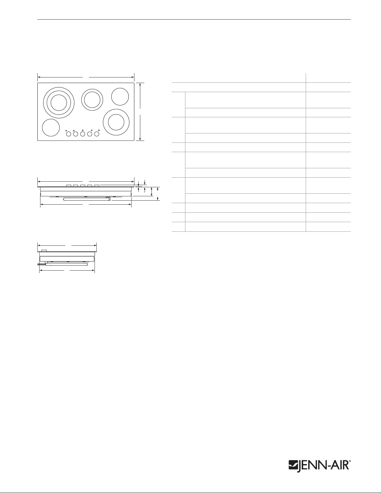
36" ELECTRIC RADIANT COOKTOP
JEC3536BS – 367⁄16" x 55⁄16" x 223⁄16"
JEC3536BB – 365⁄16" x 55⁄16" x 2111⁄16"
PRODUCT DIMENSIONS
MODEL # JEC3536B
Overall width
Euro-Style Stainless (including trim)
A
TOP VIEW
FRONT VIEW
B
A
D
F
G
C
Floating Glass 365⁄16 92.3
Overall depth
Euro-Style Stainless (including trim)
B
Floating Glass 2111⁄16 55.1
Width of recessed cooktop 347⁄16 8 7.5
C
Height of cooking surface
Euro-Style Stainless
D
Floating Glass
Height with knobs
Euro-Style Stainless
E
Floating Glass 15⁄16 3.3
Height of recessed cooktop 33⁄4 9.6
F
Recessed height including electrical conduit
G
Depth of recessed cooktop 201⁄4 51.5
H
1 of 4
in cm
367⁄16 92.6
223⁄16 56.4
5
⁄16
1
⁄4
17⁄16
0.8
0.6
3.6
55⁄16 13.5
SIDE VIEW
B
H
Product dimension, cutout and installation specifications are provided for planning purposes only. Before installing
any product, be sure to verify cutout dimensions and electrical/gas connections as actual product dimensions may vary.
7767CdZw713
Page 2
JENN-AIR® DETAILED PLANNING DIMENSIONS
D* G
E
A
B
B
C
e
F
Side
Cabinet
G
BB
H
Side
Cabinet
JENN-AIR® DETAILED PLANNING DIMENSIONS
36" ELECTRIC RADIANT COOKTOP
JEC3536BS – 367⁄16" x 55⁄16" x 223⁄16"
JEC3536BB – 365⁄16" x 55⁄16" x 2111⁄16"
2 of 4
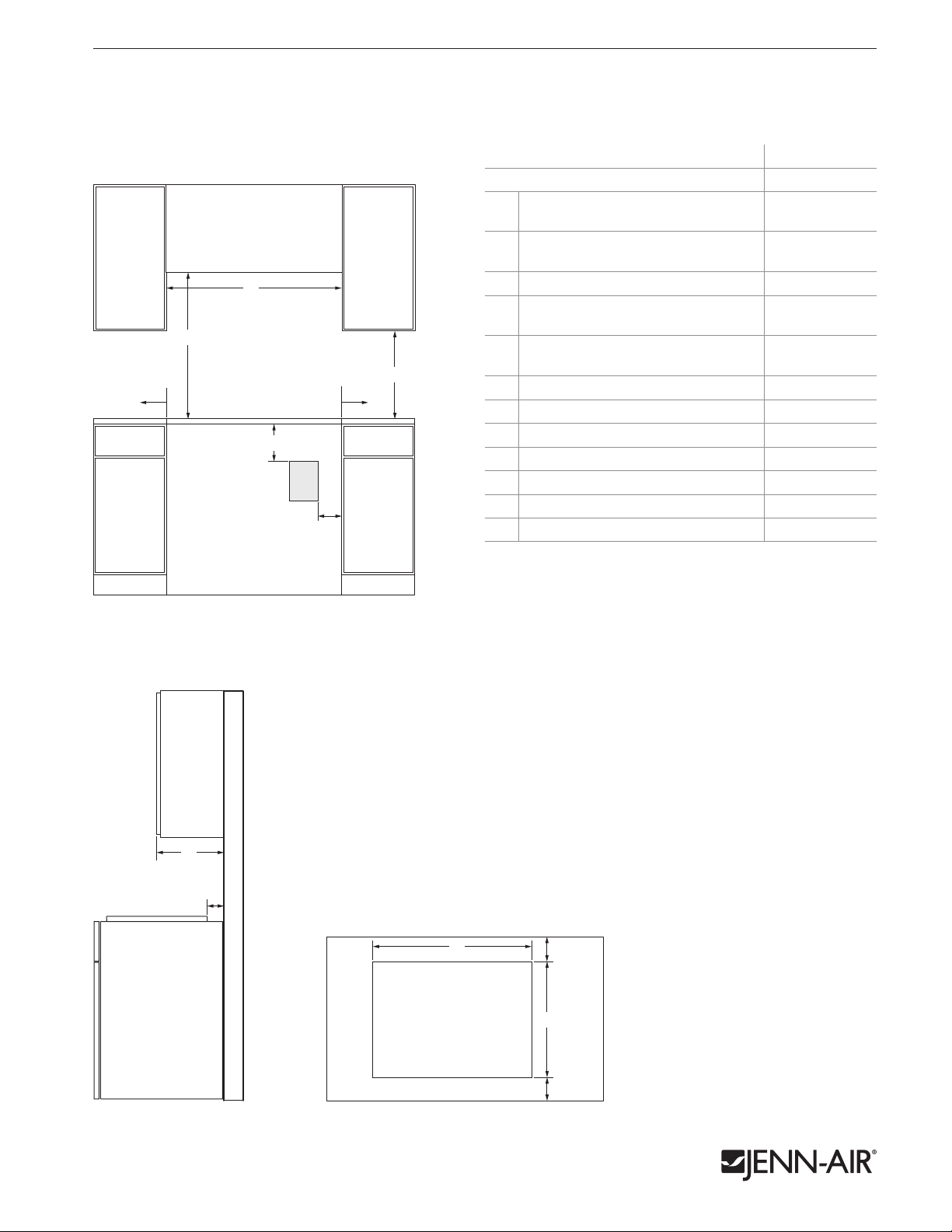
OPENING/CLEARANCE DIMENSIONS
A
D*
F
e
C
FRONT VIEW
MODEL # JEC3536B
in cm
Width of combustible area above
A
cooking surface (min.)
Width from cooktop to fixed wall or
B
other combustible material (min.)
Width to outer edge of outlet (max.) 9 23.0
C
Height to bottom of uncovered wood or
D*
metal cabinet above cooking surface (min.)
Height to bottom of uncovered wood or
E
E
metal cabinet (min.)
Height to top edge of outlet (min.) 7 17. 8
F
Depth of upper cabinet 13 33.0
G
Depth from cutout to wall (min.) 1 2.5
H
Width of cutout 351⁄2 90.2
I
Depth of cutout 201⁄2 52.0
J
Depth from cutout to front of countertop 25⁄8 6.7
K
e
Recommended electrical access location
* Dimension can be reduced by 6" (15.2 cm) when bottom of wood or metal
cabinet is covered by not less than 1⁄4" (0.6 cm) flame retardant millboard
covered with not less than No. 28 MSG sheet metal, 0.015" (0.4 mm)
stainless steel, 0.024" (0.6 mm) aluminum or 0.020" (0.5 mm) copper.
If installing a hood or microwave hood combination above the cooktop,
follow the hood or microwave hood combination instructions for
dimensional clearances above the cooking surface.
36 91.4
1 2.5
30 76.2
18 45.7
ELECTRICAL REQUIREMENTS
A 3-wire or 4-wire, single phase, 120/240 volt, 60 Hz., AC only electrical
supply is required on a separate, 40-amp circuit fused on both sides of
the line. 48" (121.9 cm) of 1⁄2" (1.3 cm) I.D. flexible cable is provided.
LOCATION REQUIREMENTS
• To ensure cooktop base clearance, cabinet side walls need to be wider
Side
Cabinet
G
H
than the cutout.
• If cabinet has a drawer, allow a 51⁄2" (14.0 cm) minimum clearance
between countertop and top of drawer.
COOKTOP OVER SINGLE WALL OVEN INSTALLATION
REQUIREMENTS
• For approved model number combinations, refer to the under counter
label on the bottom of the cooktop burner box.
• To install a cooktop over a single wall oven, refer to page 3.
I
TOP VIEWSIDE VIEW
H
J
K
Product dimension, cutout and installation specifications are provided for planning purposes only. Before installing
any product, be sure to verify cutout dimensions and electrical/gas connections as actual product dimensions may vary.
7767CdZw713
Page 3

JENN-AIR® DETAILED PLANNING DIMENSIONS
B
D
e
e
F
E
G
A
H
C
3
⁄4" (1.9 cm)
Side Cleat
3
⁄4" (1.9 cm)
Side Cleat
2" (5.1 cm)
Top Cleat
A
B
D
e
E
G
A
H
3
⁄4" (1.9 cm)
Side Cleat
3
⁄4" (1.9 cm)
Side Cleat
2" (5.1 cm)
Top Cleat
JENN-AIR® DETAILED PLANNING DIMENSIONS
SINGLE WALL OVEN AND COOKTOP COMBINATIONS
For the approved model number combinations, refer to the under counter label
located on top of the oven chassis and on the bottom of the cooktop burner box.
APPROVED MODEL NUMBER COMBINATIONS
3 of 4
SINGLE WALL OVENS
30-Inch: JJW3430W, JJW2430W, JJW2330W
27-Inch: JJW2427W, JJW2327W
INDUCTION COOKTOPS
36-Inch: JIC4536X
30-Inch: JIC4430X
OPENING/CLEARANCE DIMENSIONS
e
D
E
F
B
C C
FRONT VIEW –
UNDER COUNTER INSTALLATION
(with cooktop installed above)
SIDE VIEW –
UNDER COUNTER INSTALLATION
(with cooktop installed above)
H
GAS COOKTOPS
36-Inch: JGC7636B, JGC9536BD, JGC1536AD, JGC8536BD
30-Inch: JGC7530B, JGC9430BD, JGC1430AD
ELECTRIC COOKTOPS
36-Inch: JEC4536B, JEC3536B
30-Inch: JEC4430B, JEC3430B
JJW3430W
MODEL #
JJW2430W
JJW2330W
JJW2427W
JJW2327W
in cm in cm
Width of cabinet (min.) 30 76.2 27 68.6
e
A
Width of cutout
B
(recommended)
Oven trim overlap
C
Bottom of countertop to floor 341⁄2 87.6 341⁄2 87.6
D
281⁄2 72.4 251⁄2 64.8
5
⁄8 1.6
5
⁄8 1.6
Bottom of countertop to
G
gg
bottom of cutout
Induction cooktop
combination 307⁄8 78.4 307⁄8 78.4
E
Gas cooktop combination 297⁄8 75.9 297⁄8 75.9
Electric cooktop
combination
Height of cutout
F
(recommended)
297⁄8 75.9 297⁄8 75.9
273⁄4 70.5 273⁄4 70.5
Bottom of cutout to floor
Induction cooktop
combination 35⁄8 9.2 35⁄8 9.2
G
Gas cooktop combination 45⁄8 11.7 45⁄8 11.7
Electric cooktop
combination 45⁄8 11.7 45⁄8 11.7
Depth of cabinet (min.) 24 61.0 24 61.0
H
e
Recommended junction box location
g
Recommended gas supply line location for gas cooktop
NOTE: For under counter installation, the junction box should be located in
the adjacent right or left cabinet. Drill a 1" (2.5 cm) minimum diameter hole
in an upper corner of the side wall for access to the junction box.
CABINET REQUIREMENTS
NOTE: When using under counter installation, check cabinet manufacturer’s
specifications to verify fit.
Product dimension, cutout and installation specifications are provided for planning purposes only. Before installing
any product, be sure to verify cutout dimensions and electrical/gas connections as actual product dimensions may vary.
7767CdZw713
Page 4

JENN-AIR® DETAILED PLANNING DIMENSIONS
VENTILATION SELECTION CHART – COOKTOPS
4 of 4
ACCOLADE™
MODEL #
DOWNDRAFT
SYSTEM
JXD7836B JXD7036YS JXD7030YS JXW9048WP
TELESCOPING
DOWNDRAFT SYSTEM PRO-STYLE™ HOODS
JXW9036WP
JXU9136WP
INDUCTION COOKTOPS
36-INCH
JIC4536X – 5 Elements
n n
—
n n
30-INCH
JIC4430X – 4 Elements
n n n n n n n n n n n n n n n n
CONVENTIONAL GAS COOKTOPS
36-INCH (60,000 BTU total or more)
JGC7636B – 6 Burners
n
— —
n n
36-INCH (less than 60,000 BTU total)
JGC9536BD – 5 Burners
JGC1536AD – 5 Burners
JGC8536BD – 5 Burners
n n
n n
n n
—
—
—
n n
n n
n n
30-INCH (60,000 BTU total or more)
JGC7530B – 5 Burners
n n n n n n n n n n n n n n n
30-INCH (less than 60,000 BTU total)
JGC9430BD – 4 Burners
JGC1430AD – 4 Burners
n n n n n n n n n n n n n n n n
n n n n n n n n n n n n n n n n
CONVENTIONAL ELECTRIC COOKTOPS
36-INCH
JEC4536B – 5 Elements
JEC3536B – 5 Elements
n n
n n
—
—
n n
n n
30-INCH
JEC4430B – 4 Elements
JEC3430B – 4 Elements
A. Custom hood liners can be used with any of the following blower motors: UXB1200DYS, UXB0600DYS or UXI1200DYS.
n n n n n n n n n n n n n n n n
n n n n n n n n n n n n n n n n
GLASS
EURO-STYLE
ISLAND-MOUNT HOODS
JXW9030WP
JXU9130WP JXI8042WS JXI8036WS
—
n n n
EURO-STYLE
WALL-MOUNT HOODS
JXW8036WS
JXW8836WS JXW8030WS JXI5036WS JXW5036WS JXW5030WS JXP5032WS
—
COLLECTION
ISLAND-MOUNT
HOOD
n n
GLASS COLLECTION
WALL-MOUNT HOODS
—
PERIMETRIC
HOOD
n n n
CUSTOM
HOOD LINERS
UXL6048YSS
UXL6036YSS
A
A
— — — — — — — — — 1,200 CFM only —
—
—
—
—
—
n n n
n n n
n n n
n n n
n n n
—
—
—
—
—
n n
n n
n n
n n
n n
—
—
—
—
—
n n n
n n n
n n n
n n n
n n n
OVER-THE-
RANGE
MICROWAVE
OVENS
JMV9186W
JMV8208W
—
KEY
n
Recommended
Not Recommended
—
Product dimension, cutout and installation specifications are provided for planning purposes only. Before installing
any product, be sure to verify cutout dimensions and electrical/gas connections as actual product dimensions may vary.
7767CdZw713
 Loading...