

JENN-AIR JB36NXFXLW, JB36NXFXRW, JPK36BNXWPS, JPK36BNXWES, JF42NXFXDW Installation Instructions
...
JENN-AIR® BOTTOM MOUNT BUILT-IN REFRIGERATOR
REFRIGERADOR EMPOTRADO CON
CONGELADOR EN LA PARTE INFERIOR JENN-AIR
®
RÉFRIGÉRATEUR ENCASTRÉ AVEC CONGÉLATEUR
EN BAS JENN-AIR
®
INSTALLATION GUIDE
For questions about features, operation/performance, parts, accessories, or service, call:
1-800-JENNAIR (1-800-536-6247) or visit our website at www.jennair.com.
In Canada, call: 1-800-807-6777, or visit our website at www.jennair.ca.
MANUAL DE INSTALACIÓN
Si tiene preguntas respecto a las características, funcionamiento, rendimiento, partes, accesorios o servicio técnico, llame al:
1-800-JENNAIR (1-800-536-6247) o visite nuestro sitio de internet: www.jennair.com.
En Canadá, llame al: 1-800-807-6777, o visite nuestro sitio de internet: www.jennair.ca.
GUIDE D’INSTALLATION
Au Canada, pour assistance, installation ou service, composez le 1-800-807-6777 ou visitez notre site web à www.jennair.ca.
Table of Contents/Índice/Table des matières ......................................................................................2
W10231367A

TABLE OF CONTENTS
REFRIGERATOR SAFETY...........................................................................3
36" MODELS ................................................................................................4
Euro-Style and Pro-Style
42" FRENCH DOOR MODELS....................................................................5
Euro-Style and Pro-Style
INSTALLATION REQUIREMENTS .............................................................6
Tools and Parts.........................................................................................6
Location Requirements.............................................................................6
Electrical Requirements............................................................................7
Water Supply Requirements.....................................................................8
Product Dimensions .................................................................................8
Tipping Radius..........................................................................................9
Door Swing Dimensions ...........................................................................9
Cabinet and Panel Installation Options..................................................10
Fully Integrated Installation Requirements.............................................10
®
Door Handle Kits...........................................4
®
Door Handle Kits............................................5
ÍNDICE
SEGURIDAD DEL REFRIGERADOR........................................................23
MODELOS DE 36" .....................................................................................24
Juegos de manijas para puertas Euro-Style y Pro-Style
MODELOS DE DOS PUERTAS CON CONGELADOR
EN LA PARTE INFERIOR, DE 42" ............................................................25
Juegos de manijas para puertas Euro-Style y Pro-Style
REQUISITOS DE INSTALACIÓN ..............................................................26
Piezas y herramientas.............................................................................26
Requisitos de ubicación .........................................................................26
Requisitos eléctricos...............................................................................27
Requisitos del suministro de agua .........................................................28
Dimensiones del producto......................................................................28
Arco de vuelco........................................................................................29
Medidas de oscilación de las puertas....................................................29
Opciones para la instalación del armario y los paneles......................... 30
Requisitos para la instalación completamente incorporada.................. 30
®
.....................24
®
.....................25
Custom Overlay Panels .......................................................................... 11
Overlay Panel Dimensions...................................................................... 12
INSTALLATION INSTRUCTIONS .............................................................13
Unpack the Refrigerator .........................................................................13
Move the Refrigerator into House .......................................................... 13
Install Anti-Tip Boards ............................................................................ 13
Connect the Water Supply .....................................................................14
Plug in Refrigerator.................................................................................15
Move Refrigerator to Final Location....................................................... 16
Level and Align Refrigerator ................................................................... 16
Install Refrigerator and Overlay Panels .................................................. 17
Install Handles ........................................................................................ 21
Install Base Grille .................................................................................... 21
Complete Installation..............................................................................22
Water System Preparation ..................................................................... 22
Paneles recubiertos a la medida ............................................................31
Dimensiones de los paneles recubiertos ...............................................32
INSTRUCCIONES DE INSTALACIÓN...................................................... 33
Desempaque el refrigerador...................................................................33
Cómo introducir el refrigerador en la casa............................................. 33
Cómo instalar los tableros antivuelco .................................................... 33
Conexión del suministro de agua...........................................................34
Cómo enchufar el refrigerador ............................................................... 35
Cómo mover el refrigerador a su ubicación final ................................... 36
Nivelación y alineamiento del refrigerador ............................................. 36
Instalación del refrigerador y los paneles recubiertos ........................... 37
Instalación de las manijas.......................................................................41
Instalación de la rejilla de la base........................................................... 41
Cómo terminar la instalación..................................................................42
Preparación del sistema de agua...........................................................42
TABLE DES MATIÈRES
SÉCURITÉ DU RÉFRIGÉRATEUR ...........................................................43
MODÈLES DE 36"......................................................................................44
Ensembles de poignées de porte Euro-Style et Pro-Style
MODÈLES DE PORTE À DOUBLE BATTANT DE 42"............................45
Ensembles de poignées de porte Euro-Style et Pro-Style
EXIGENCES D’INSTALLATION................................................................46
Outillage et pièces ..................................................................................46
Exigences d'emplacement .....................................................................46
Spécifications électriques ......................................................................47
Spécifications de l’alimentation en eau..................................................48
Dimensions du produit............................................................................48
Rayon de basculement...........................................................................49
Dimensions pour l’ouverture des portes ................................................49
Options d’installation du placard et du panneau ...................................50
Exigences d’une installation intégrée.....................................................50
®
..................44
®
..................45
Panneaux décoratifs sur mesure............................................................ 51
Dimensions des panneaux décoratifs.................................................... 52
INSTRUCTIONS D’INSTALLATION .........................................................53
Déballage du réfrigérateur...................................................................... 53
Déplacement du réfrigérateur dans le domicile ..................................... 53
Installation de planches antibasculement..............................................54
Raccordement à l'alimentation en eau...................................................54
Brancher le réfrigérateur.........................................................................56
Déplacement du réfrigérateur à son emplacement définitif................... 56
Réglage de l'aplomb et alignement du réfrigérateur.............................. 56
Installation du réfrigérateur et des panneaux décoratifs .......................57
Installation des poignées........................................................................62
Installation de la grille de la base ...........................................................62
Achever l’installation...............................................................................63
Préparation du système d’eau ............................................................... 63
2
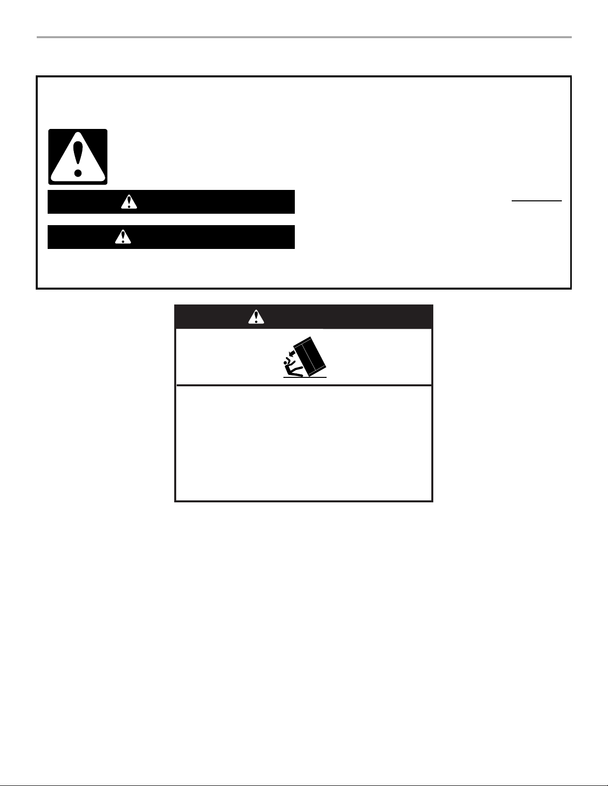
REFRIGERATOR SAFETY
Your safety and the safety of others are very important.
We have provided many important safety messages in this manual and on your appliance. Always read and obey all safety
messages.
This is the safety alert symbol.
This symbol alerts you to potential hazards that can kill or hurt you and others.
All safety messages will follow the safety alert symbol and either the word “DANGER” or “WARNING.”
These words mean:
You can be killed or seriously injured if you don't immediately
DANGER
WARNING
All safety messages will tell you what the potential hazard is, tell you how to reduce the chance of injury, and tell you what can
happen if the instructions are not followed.
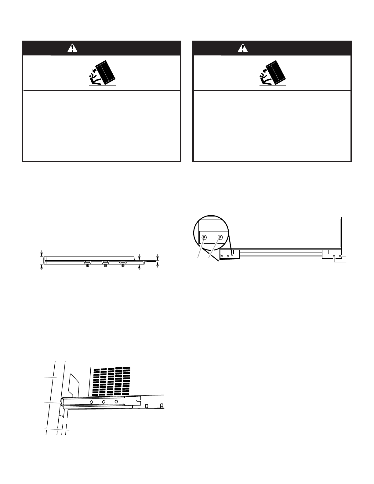
WARNING
follow instructions.
can be killed or seriously injured if you don't
You
instructions.
follow
Tip Over Hazard
Refrigerator is top heavy and tips easily when not
completely installed.
Keep doors taped closed until refrigerator is
completely installed.
Use two or more people to move and install
refrigerator.
Failure to do so can result in death or serious injury.
3
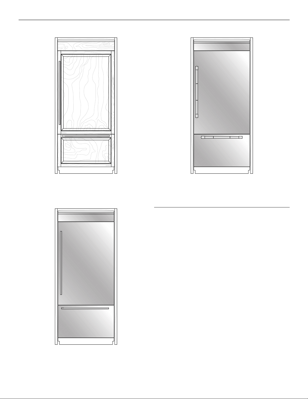
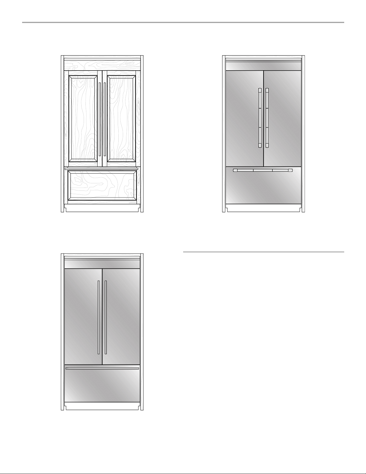
36" MODELS
Integrated Design
Features custom-made panels and custom hardware provided
by the cabinetmaker for a seamless appearance designed to
blend with existing kitchen cabinetry.
Base Model Numbers: JB36NXFXLW, JB36NXFXRW
Pro-Style® Stainless Design
Features stainless steel wrapped doors and Pro-Style® handles with
diamond-etched grip.
Base Model Numbers: JB36NXFXLW, JB36NXFXRW
Kit Model Numbers: JPK36BNXWPS
Euro-Style and Pro-Style
All factory parts are available through your Jenn-Air dealer or by
calling Jenn-Air at 1-800-JENNAIR (1-800-536-6247). In Canada,
call 1-800-807-6777.
Follow the kit instructions for installing the door handles.
Pro-Style
Euro-Style Stainless Steel - BM W10250635
®
Stainless Steel - BM W10250641
®
Door Handle Kits
Euro-Style Stainless Design
Features stainless steel wrapped doors and new Euro-style handles
designed to compliment the Jenn-Air Euro kitchen suite or enhance
any kitchen decor.
Base Model Numbers: JB36NXFXLW, JB36NXFXRW
Kit Model Number: JPK36BNXWES
4
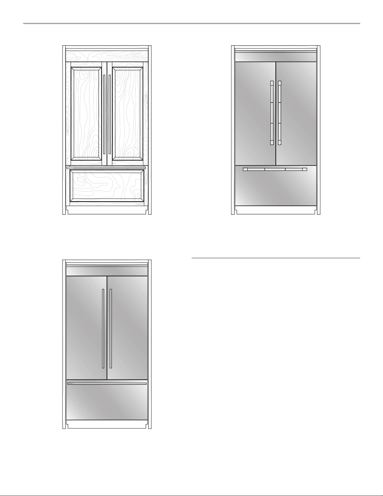
42" FRENCH DOOR MODELS
Integrated Design
Uses custom-made panels and custom hardware provided by the
cabinetmaker for a seamless appearance designed to blend with
existing kitchen cabinetry.
Base Model Number: JF42NXFXDW
®
Pro-Style
Features stainless steel wrapped doors and Pro-Style® handles with
diamond-etched grip.
Base Model Number: JF42NXFXDW
Kit Model Numbers: JPK42FNXWPS
Stainless Design
Euro-Style and Pro-Style® Door Handle Kits
All factory parts are available through your Jenn-Air dealer or by
calling Jenn-Air at 1-800-JENNAIR (1-800-536-6247). In Canada,
call 1-800-807-6777.
Follow the kit instructions for installing the door handles.
Pro-Style
Euro-Style Stainless Steel - FDBM W10250636
®
Stainless Steel - FDBM W10250642
Euro-Style Stainless Design
Features stainless steel wrapped doors and new Euro-style handles
designed to compliment the Jenn-Air Euro kitchen suite or enhance
any kitchen decor.
Base Model Number: JF42NXFXDW
Kit Model Number: JPK42FNXWES
5

INSTALLATION REQUIREMENTS
Tools and Parts
IMPORTANT:
■ Installer: Leave Installation Instructions with the homeowner.
■ Homeowner: Keep Installation Instructions for future
reference. Save these Installation Instructions for the local
electrical inspector’s use.
TOOLS NEEDED:
Gather the required tools and parts before starting installation.
Read and follow the instructions provided with any tools listed
here.
■ Cordless drill
■ Drill bits
■ Two adjustable
wrenches
■ Phillips screwdriver
■ Small level
■ Appliance dolly
■ ³⁄₃₂" Allen wrench
(panel kits only)
PARTS NEEDED:
■ Six #8 x 3" (7.6 cm) wood screws (longer screws may be needed)
■ One or two 2" x 4" x 32" (5 cm x 10 cm x 81 cm) wood board(s)
■ Integrated design - consult a qualified cabinetmaker or
carpenter to make the custom wood panels. See “Integrated
Series Custom Overlay Panels” for more information.
Stainless Steel design - the panel kit is shipped with the
refrigerator.
■ Flexible, codes approved water supply tubing, a ferrule, a
union and a ¹⁄₄" (6.35 mm) compression fitting.
■ ¹¹⁄₃₂" nut driver
■ ³⁄₈" and ¹⁄₂" open-end wrenches
■ ⁵⁄₃₂" and ³⁄₁₆" Allen wrench
■ ¹⁄₄" and ⁵⁄₁₆" socket drivers
■ Tap e m e as ure
■ Utility knife
■ Tape (painters)
Location Requirements
WARNING
Explosion Hazard
Keep flammable materials and vapors, such as
gasoline, away from refrigerator.
Failure to do so can result in death, explosion, or fire.
IMPORTANT:
■ Observe all governing codes and ordinances.
■ It is recommended that you do not install the refrigerator near
an oven, radiator, or other heat source.
■ Do not install in a location where the temperature will fall
below 55°F (13°C).
■ Floor must support the refrigerator weight, more than 600 lbs
(272 kg), door panels and contents of the refrigerator.
■ Ceiling height must allow for side tipping radius. See “Tipping
Radius.”
■ Location should permit door to open fully. See “Door Swing
Dimensions.”
■ Location must permit top grille removal. See “Opening
Dimensions.”
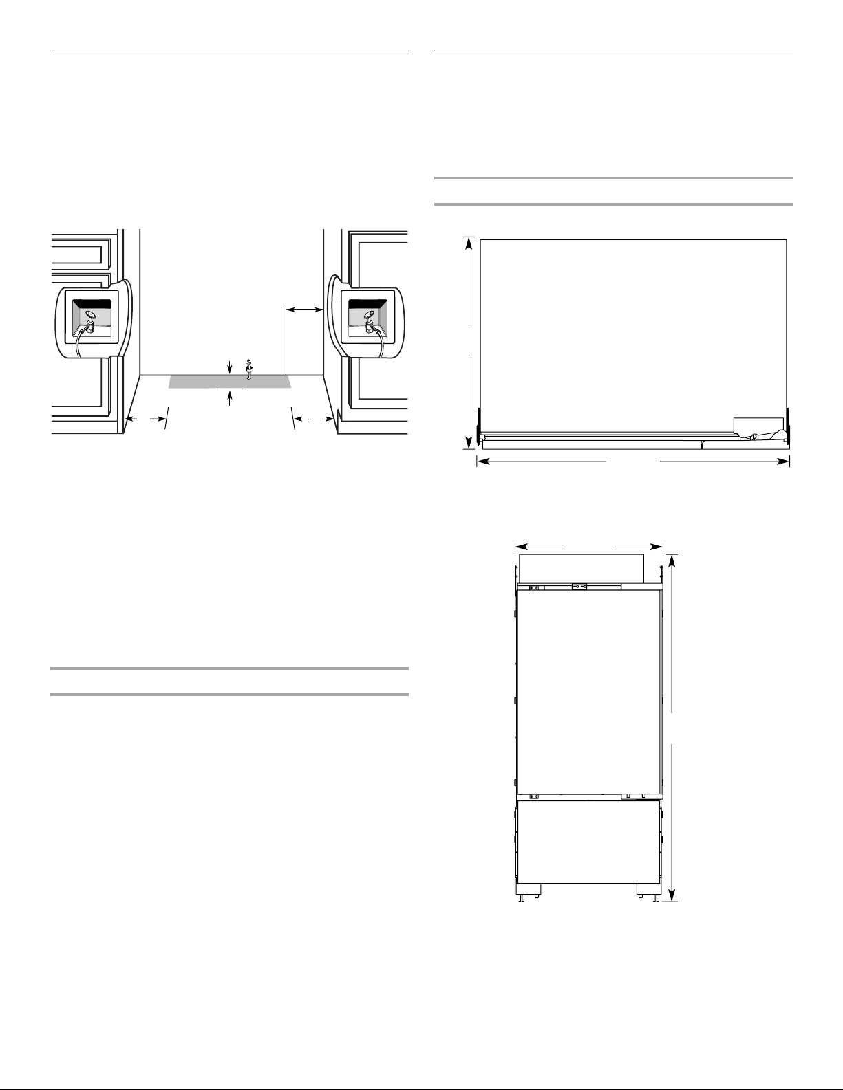
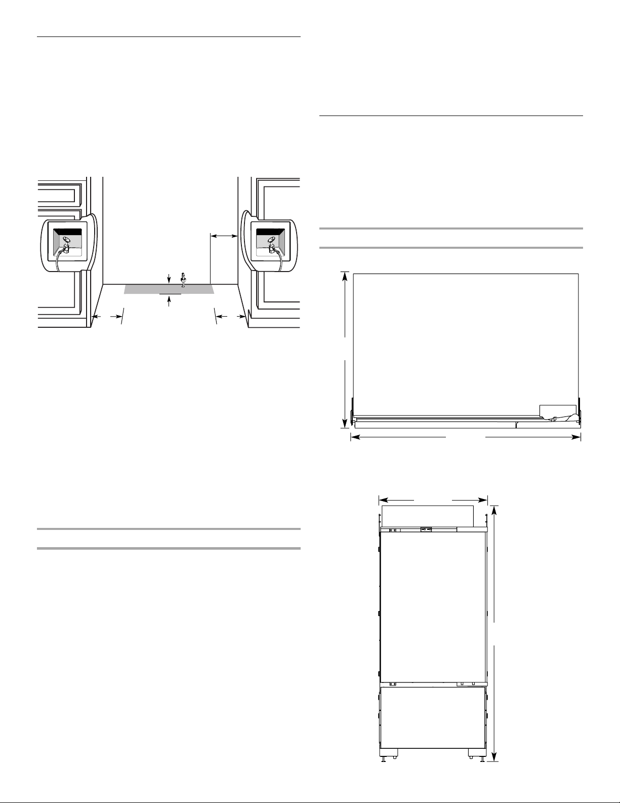
Opening Dimensions
■ A solid soffit or wall cabinet must be installed 84" (213.4 cm)
above the floor. If the solid soffit is higher than 84" (213.4 cm)
or one is not available, then the refrigerator must be braced.
If the anti-tip boards are needed, they must be attached to the
rear wall studs so that there is 84" (213.4 cm) from the bottom
of the anti-tip board to the floor. See “Install Anti-Tip Boards”
for more information.
■ For a fully integrated installation, a minimum of 6" (15.24 cm)
of open space above the refrigerator is required. See “Fully
Integrated Installation.” Anti-tip boards are required. See
“Install Anti-Tip Boards” for more information.
■ The width of the opening, from side to side, must be as
specified for your model, for at least 2" (5.08 cm) back from
the face of the cabinet. If your opening does not meet this
requirement, you will need to make modifications.
■ A grounded 3 prong electrical outlet should be placed within
4" (10.2 cm) of the right side cabinets or end panel. See
“Electrical Requirements” for more information.
6
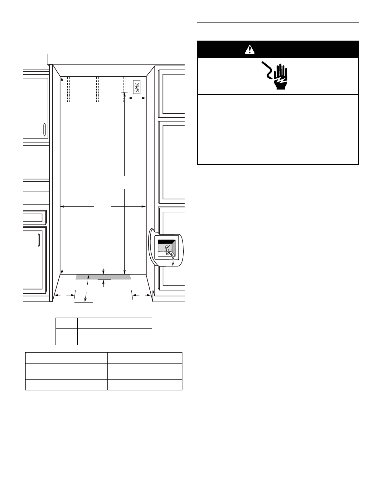
■ The water shutoff should be located in the base cabinet on
either side of the refrigerator or some other easily accessible
area. If the water shutoff valve is not in the cabinets, the
plumbing for the water line can come through the floor. See
“Water Supply Requirements” for more information.
80" - 90"
(203-229 cm)
84" (213.4 cm)
to bottom of solid soffit
(see chart following)
B
6"
(15.2 cm)
A
Width
1"
(2.54 cm)
4"
(10.2 cm)
77"
(196 cm)
6"
(15.2 cm)
Electrical Requirements
WARNING
Electrical Shock Hazard
Plug into a grounded 3 prong outlet.
Do not remove ground prong.
Do not use an adapter.
Do not use an extension cord.
Failure to follow these instructions can result in death,
fire, or electrical shock.
Before you move your refrigerator into its final location, it is
important to make sure you have the proper electrical connection.
Recommended Grounding Method
A 115 Volt, 60 Hz., AC only, 15- or 20-amp fused, grounded
electrical supply is required. It is recommended that a separate
circuit serving only your refrigerator be provided. Use an outlet
that cannot be turned off by a switch. Do not use an
extension cord.
IMPORTANT: If this product is connected to a GFCI (Ground Fault
Circuit Interrupter) protected outlet, nuisance tripping of the
power supply may occur, resulting in loss of cooling. Food quality
and flavor may be affected. If nuisance tripping has occurred, and
if the condition of the food appears poor, dispose of it.
NOTE: Before performing any type of installation, cleaning, or
removing a light bulb, remove the top grille and turn the master
power switch to OFF or disconnect power at the circuit breaker
box.
When you are finished, turn ON the master power switch or
reconnect power at the circuit breaker box. Then reset the control
to the desired setting.
Model Width A (as shown above)
36
42
36" (91.4 cm)
42" (106.7 cm)
Installation Type Depth B (as shown above)
Standard Flush
25" (63.5 cm) minimum
(new installation)
Retrofit Installations 24" (60.9 cm) minimum
IMPORTANT:
■ Flooring under refrigerator must be at same level as the
room. Face of cabinetry must be plumb.
■ The width of the opening (Width A), must be as specified
for your model, for at least 2" (5.08 cm) back from the face
of the cabinet. If your opening does not meet this
requirement, you will need to make modifications.
7
Water Supply Requirements
■ All installations must meet local plumbing code requirements.
■ The water supply line must come up through the floor in the
gray shaded area shown.
■ The water shutoff should be located in the base cabinet on
either side of the refrigerator or some other easily accessible
area. The right-hand side is recommended.
NOTE: There is not enough clearance to achieve a flush
installation if a water shutoff valve is located in the wall behind
the refrigerator.
6"
(15.2 cm)
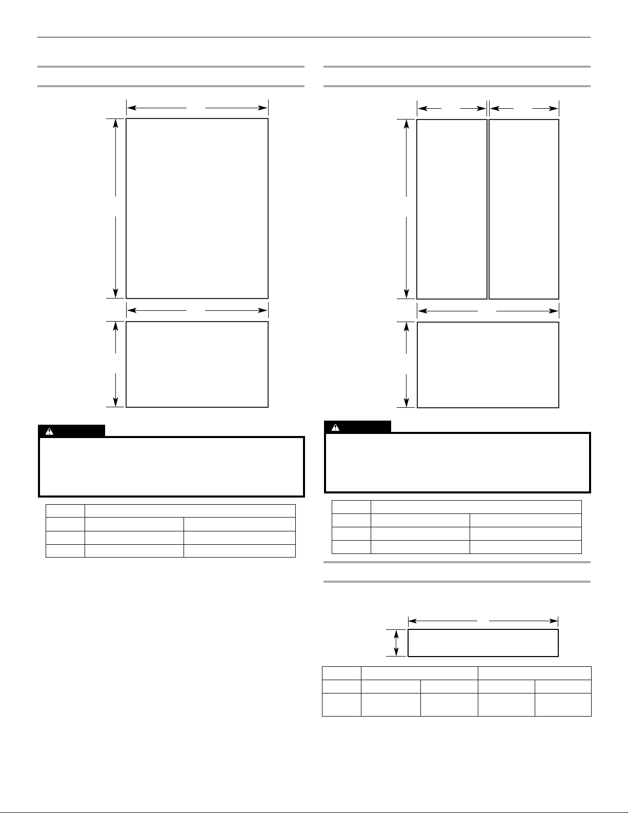
Product Dimensions
IMPORTANT:
■ The depth from the front face of the doors to the back of the
refrigerator cabinet is 24" (60.96 cm) without panels.
■ The power cord is 84" (213 cm) long.
■ The water supply line is located at the front of the refrigerator.
36" Bottom-Mount
Top Vi ew
24"
(61.0 cm)
6"
(15.2 cm)
■ A ¹⁄₂" (12.7 mm) hole for plumbing should be drilled at least 6"
1"
(2.54 cm)
6"
(15.2 cm)
(15.2 cm) from the right or left hand side cabinet or panel. On
the floor, the hole should be no more than 1" (2.54 cm) away
from the back wall. See “Connect the Water Supply.”
■ If additional tubing is needed, use copper tubing and check
for leaks. Install the copper tubing only in areas where the
household temperatures will remain above freezing.
■ Do not use a piercing-type or ³⁄₁₆" (4.76 mm) saddle valve
which reduces water flow and clogs more easily.
NOTE: Your refrigerator dealer has a kit available with a ¹⁄₄"
(6.35 mm) saddle-type shutoff valve, a union, and copper
tubing. Before purchasing, make sure a saddle-type valve
complies with your local plumbing codes.
Water Pressure
A cold water supply with water pressure between 30 and 120 psi
(207 and 827 kPa) is required to operate the water dispenser and
ice maker. If you have questions about your water pressure, call a
licensed, qualified plumber.
Reverse Osmosis Water Supply
IMPORTANT: The pressure of the water supply coming out of a
reverse osmosis system going to the water inlet valve of the
refrigerator needs to be between 30 and 120 psi
(207 and 827 kPa).
If a reverse osmosis water filtration system is connected to your
cold water supply, the water pressure to the reverse osmosis
system needs to be a minimum of 40 to 60 psi (276 to 414 kPa).
If the water pressure to the reverse osmosis system is less than
40 to 60 psi (276 to 414 kPa):
■ Check to see whether the sediment filter in the reverse
osmosis system is blocked. Replace the filter if necessary.
■ Allow the storage tank on the reverse osmosis system to refill
after heavy usage.
■ If your refrigerator has a water filter, it may further reduce the
water pressure when used in conjunction with a reverse
osmosis system. Remove the water filter cartridge.
If you have questions about your water pressure, call a licensed,
qualified plumber.
35³⁄₄"
(90.8 cm)
Front View
■ Width dimensions were measured from hinge edge to clip
edge.
35³⁄₄"
(90.8 cm)
84"
(213.4 cm)
8
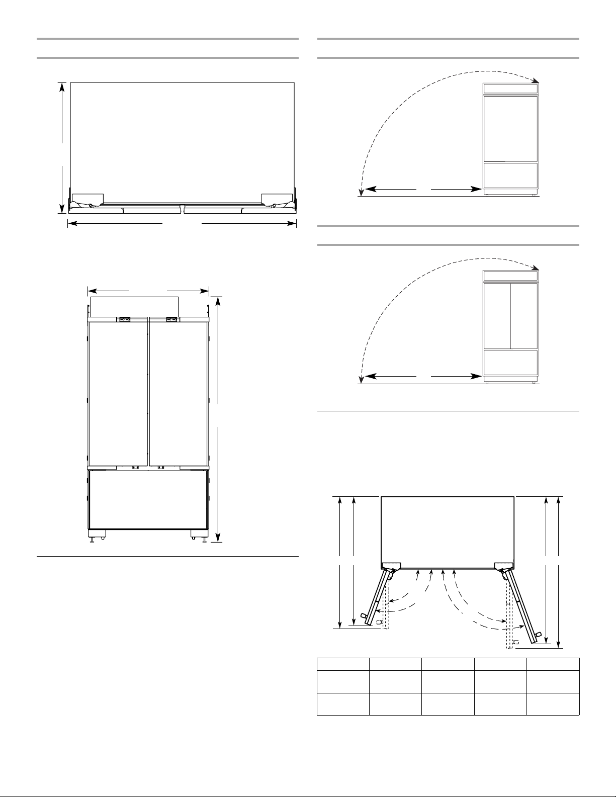
42" French-Door Bottom-Mount
Top Vi ew
24"
(61.0 cm)
41³⁄₄"
(106.1 cm)
Front View
■ Width dimensions were measured from hinge edge to hinge
edge.
41³⁄₄"
(106.1 cm)
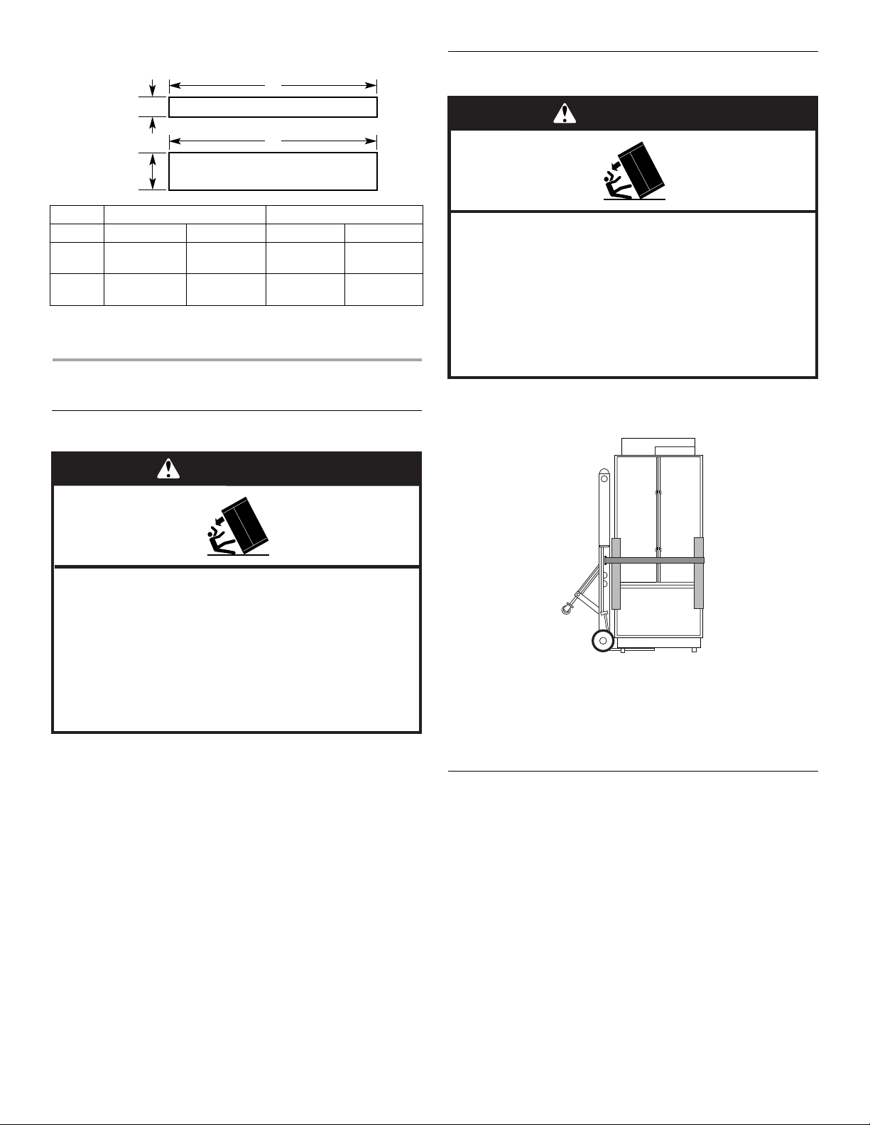
Side Tipping Radius (36" [91.4 cm] Models)
A
A. 88
⁷⁄₈
" (225.7 cm)
Side Tipping Radius (42" [106.7 cm] Models)
84"
(213.4 cm)
Tipping Radius
Be sure there is adequate ceiling height to stand the refrigerator
upright when it is moved into place.
■ The dolly wheel height must be added to the tipping radius
when a dolly is used.
■ If needed, the tipping radius can be reduced. See “Reduce
Tipping Radius.”
NOTE: Tip on side only.
A
A. 91
³⁄₈
" (232.1 cm)
Door Swing Dimensions
The location must permit both doors to open to a minimum of 90°.
Allow 4¹⁄₂" (11.4 cm) minimum space between the side of the
refrigerator and a corner wall.
NOTE: More clearance may be required if you are using overlay
panels, custom handles, or extended handles.
BA C D
90˚
110˚
Model A B C D
36 36"
(91.4 cm)
42 42"
(106.7 cm)
39³⁄₄"
(101.0 cm)
42"
(106.7 cm)
90˚
110˚
45³⁄₈"
(115.3 cm)
48⁵⁄₈
(123.5 cm)
46³⁄₄"
(118.8 cm)
50¹⁄₄
(127.6 cm)
9
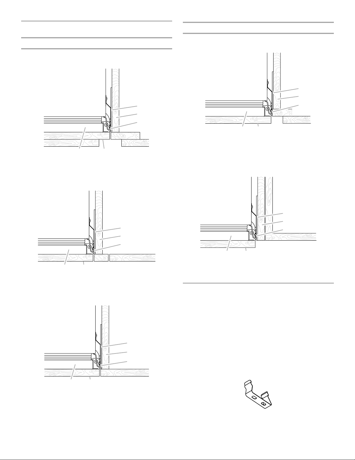
Cabinet and Panel Installation Options
Cabinet Depth - 25" (63.5 cm)
Framed Cabinetry
Top View - Overlay
E
D
C
A B
Cabinet Depth - 24" (60.9 cm)
Framed Cabinetry
Top V iew
A B
A. Refrigerator door
B. Overlay panel
C.Side trim
E
D
C
D. Adjacent cabinet
E. Grille bracket
A. Refrigerator door
B. Overlay panel
C. Side trim
Top View - Inset
A B
A. Refrigerator door
B. Overlay panel
C. Side trim
Frameless Cabinetry
D. Adjacent cabinet
E. Grille bracket
E
D
C
D. Adjacent cabinet
E. Grille bracket
E
D
C
Frameless Cabinetry
Top V iew
E
D
C
A B
A. Refrigerator door
B. Overlay panel
C. Side trim
D. Adjacent Cabinet
E. Grille bracket
Fully Integrated Installation Requirements
The refrigerator can be installed fully integrated if the adjacent
cabinetry meets the airflow venting requirements critical to
refrigerator performance.
IMPORTANT:
■ Both Standard and Fully Integrated installations can be
achieved with either a 24" (60.9 cm) or 25" (63.5 cm) deep
opening.
■ A full height grille is used to achieve a fully integrated
installation. Use the integrated bracket (provided) to attach the
full height grille.
NOTE: A top grille filler is not required with a full height grille.
Integrated Grille Bracket
10
A B
A. Refrigerator door
B. Overlay panel
C. Side trim
D. Adjacent cabinet
E. Grille bracket
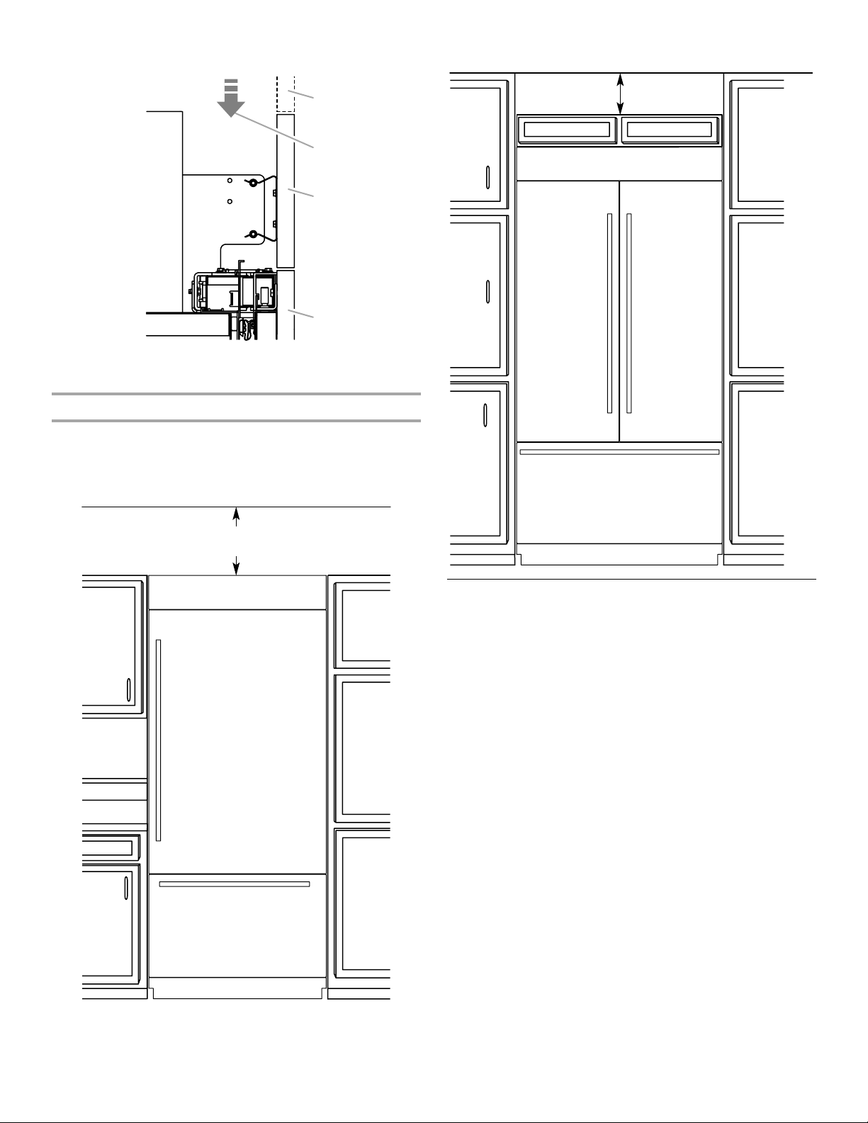
Fully Integrated Installation - Side View
A
B
C
D
Option 2 - False Front (cabinet face only)
6" (15.24 cm)
min.
A. False front (optional)
B. Airflow
C. Full height grille
D. Door panel
Airflow Venting Requirements
Fully integrated installations require a minimum of 6" (15.24 cm) of
open space above the refrigerator. This space must not be
blocked in any way, including soffits.
Option 1 - Open to Ceiling
6" (15.24 cm)
min.
Custom Overlay Panels
Custom overlay panels allow you to blend the exterior of your
refrigerator into the overall kitchen décor and to use custom
handles for additional design flexibility.
In some cases, your cabinet manufacturer may choose to work
with one panel routed for the different dimensions. Follow these
panel dimension and placement instructions to be sure that the
custom overlay panels will fit properly.
IMPORTANT:
■ For 36" (91.4 cm) models, the refrigerator door overlay panel
cannot exceed 60 lbs (27.2 kg) and the freezer drawer overlay
panel cannot exceed 25 lbs (11.3 kg).
■ For 42" (106.7 cm) models, the refrigerator door overlay panel
cannot exceed 40 lbs (18.1 kg) and the freezer drawer overlay
panel cannot exceed 30 lbs (13.6 kg).
■ The weight of the top grille overlay panel cannot exceed 7 lbs
(3.2 kg) for both models.
■ The required thickness for all panels is ³⁄₄" (1.91 cm).
■ This installation does not require filler or backer panels.
11
Overlay Panel Dimensions
36" (91.4 cm) Model - Door and Drawer Panels 42" (106.7 cm) Model - Door and Drawer Panels
52³⁄₈"
(133.03 cm)
20¹⁄₂"
(52.07 cm)
A
REFRIGERATOR DOOR PANEL
Maximum Weight: 60 lbs (27.2 kg)
B
FREEZER DRAWER PANEL
Maximum Weight: 25 lbs (11.34 kg)
52³⁄₈"
(133.03 cm)
20¹⁄₂"
(52.07 cm)
A
REFRIGERATOR
DOOR PANEL
Maximum Weight:
40 lbs (18.14 kg)
FREEZER DRAWER PANEL
Maximum Weight: 30 lbs (13.6 kg)
REFRIGERATOR
DOOR PANEL
Maximum Weight:
40 lbs (18.14 kg)
B
A
CAUTION
Pinch Hazard
Installation of door panels with less than a ³⁄₈" (0.95 cm) gap
between the door panel and the adjacent cabinet increases
the risk of potential pinching.
Model 36" Bottom-Mount
Reveal ³⁄₈" ¹⁄₈"
A 35¹⁄₄" (89.54 cm) 35³⁄₄" (90.81 cm)
B 35¹⁄₄" (89.54 cm) 35³⁄₄" (90.81 cm)
CAUTION
Pinch Hazard
Installation of door panels with less than a ³⁄₈" (0.95 cm) gap
between the door panel and the adjacent cabinet increases
the risk of potential pinching.
Model 42" French Door Bottom-Mount
Reveal ³⁄₈" ¹⁄₈"
A 20 ⁹⁄₁₆" (52.23 cm) 20¹³⁄₁₆" (52.86 cm)
B 41¹⁄₄" (104.76 cm) 41³⁄₄" (106.05 cm)
Grille Panel
Integrated Installation - Full Height Grille
C
⁵⁄₈"
6
(16.83 cm)
Model 36 42
Reveal ³⁄₈" ¹⁄₈" ³⁄₈" ¹⁄₈"
C 35¹⁄₄"
(89.54 cm)
35³⁄₄"
(90.81 cm)
Top Grille Panel
41¹⁄₄"
(104.76 cm)
41³⁄₄"
(106.05 cm)
12
Standard Installation - Flush Grille
D
1" (2.54 cm)
³⁄₄"
5
(14.55 cm)
Model 36 42
Reveal ³⁄₈" ¹⁄₈" ³⁄₈" ¹⁄₈"
D 35¹⁄₄"
(89.54 cm)
E 35¹⁄₄
(89.54 cm)
IMPORTANT: The grille panel height, shown in the Standard
Installation Flush Grille graphic, allows for an air gap critical to
refrigerator performance.
35³⁄₄"
(90.81 cm)
35³⁄₄"
(90.81 cm)
Top Grille Filler
E
Top Grille Panel
41¹⁄₄"
(104.76 cm)
41¹⁄₄"
(104.76 cm)
41³⁄₄"
(106.05 cm)
41³⁄₄"
(106.05 cm)
Move the Refrigerator into House
WARNING
Tip Over Hazard
Refrigerator is top heavy and tips easily when not
completely installed.
Keep doors taped closed until refrigerator is
completely installed.
Use two or more people to move and install
refrigerator.
Failure to do so can result in death or serious injury.
INSTALLATION INSTRUCTIONS
Unpack the Refrigerator
WARNING
Tip Over Hazard
Refrigerator is top heavy and tips easily when not
completely installed.
Keep doors taped closed until refrigerator is
completely installed.
Use two or more people to move and install
refrigerator.
Failure to do so can result in death or serious injury.
IMPORTANT:
■ Do not remove the film covering until the refrigerator is in its
operating location.
■ All four leveling legs must contact the floor to support and
stabilize the full weight of the refrigerator.
■ Keep the cardboard shipping piece or plywood under the
refrigerator until it is installed in the operating location.
1. Remove and save the literature package bag taped to the side
of the refrigerator and the parts bag behind the grille. Remove
the four brackets (two on each side) that attach the shipping
base to the refrigerator bottom.
NOTE: Do not remove tape and door bracing until the
refrigerator is in its final location.
2. If necessary, reduce the tipping radius. See “Tipping Radius”
for ceiling height requirements.
1. Place an appliance dolly under the left side of the refrigerator
as shown. Place the corner posts from the packing materials
over the trims as appropriate. Slowly tighten the strap.
2. Place pieces of the shipping carton on the floor when rolling
the dolly and refrigerator into the house. Move the refrigerator
close to the built-in opening.
3. Place top of cardboard carton or plywood under refrigerator.
4. Stand the refrigerator up. First, place the left bottom edge of
the refrigerator on the floor, stand the refrigerator upright and
then lower the right-hand side of the refrigerator to the floor.
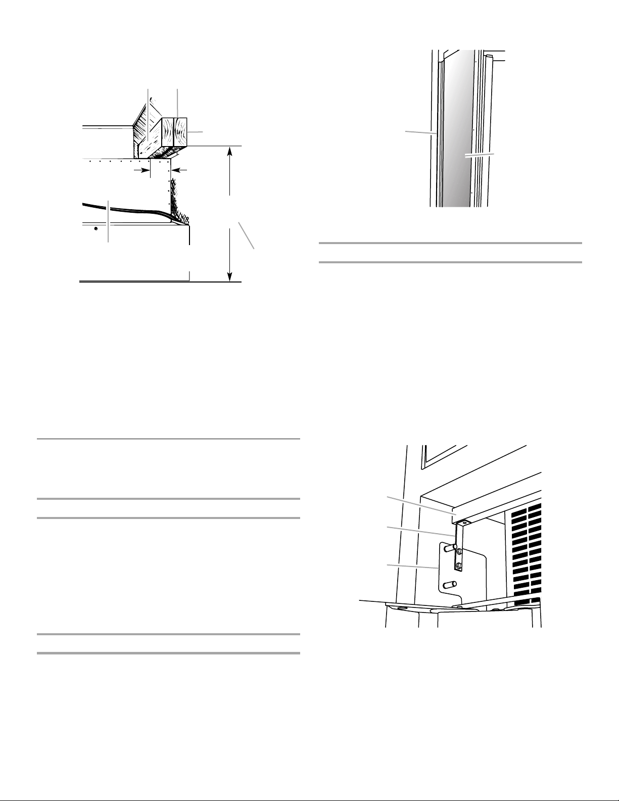
Install Anti-Tip Boards
IMPORTANT:
■ If a solid soffit is not available, an anti-tip board must be
installed.
■ It is recommended that board(s) be installed before the
refrigerator is installed.
■ Board(s) must be long enough to fully cover the width of the
compressor cover.
■ Locate the board(s) so the bottom surface(s) of the board(s)
is(are) 84" (213 cm) from the floor.
■ During installation, raise the refrigerator up so there is
¹⁄₄" (6.35 mm) maximum between the top of the refrigerator
and the bottom of the anti-tip board(s). Do not crush the
compressor cover when raising the rear leveling legs.
13
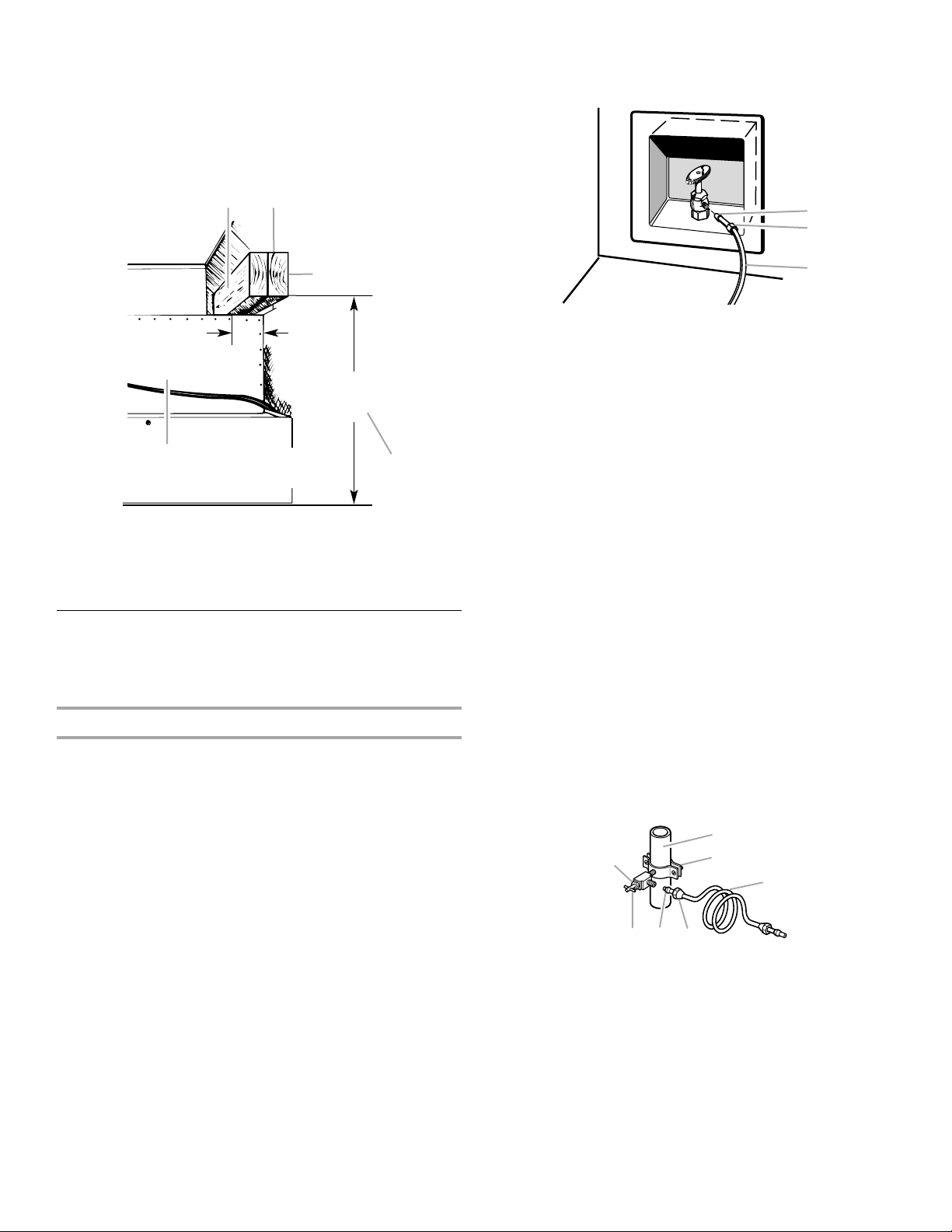
To Install Anti-tip Boards
E
A
B
C
1. Mark the stud locations on rear wall 80" to 90" (203 cm to
229 cm) above floor.
2. Securely attach one or two 2" x 4" x 32" (5 cm x 10 cm x
81 cm) boards to wall studs behind refrigerator. Use six
#8 x 3" (7.6 cm) (or longer) wood screws. The wood screws
must be screwed into the studs at least 1½" (3.8 cm). The
board(s) must overlap the compressor cover.
BA
C
¹⁄₄" (6 mm)
max.
2" (5 cm)
84"
(213.4 cm)
2. Connect the flexible, codes approved water supply line to the
water shutoff valve by threading the provided nut onto the
shutoff valve as shown.
A. Bulb
B. Nut
C. Water tubing
3. Place the end of the tubing into a bucket, and turn shutoff
valve ON.
4. Check for leaks. Tighten any nuts or connections (including
connections at the valve) that leak.
D
A. Center board
B. Two 2" x 4" x 32" (5 cm x 10 cm x 81 cm) boards
C. Attach to studs with six #8 x 3" (7.6 cm) screws
D. Compressor cover
E. Distance from bottom of anti-tip board to floor
¹⁄₄
" (6.35 mm) max. above refrigerator
Connect the Water Supply
Read all directions before you begin.
IMPORTANT: If you turn the refrigerator on before the water line is
connected, turn the ice maker OFF.
Connect to Water Line
Parts Needed:
■ Minimum 7 ft (2.13 m) flexible, codes approved water
supply line
Style 1 - Shutoff Valve Connection
NOTE: If your water line connection does not look like Style 1, see
“Style 2 - Copper Line Connection.”
1. Unplug refrigerator or disconnect power supply.
IMPORTANT: Before attaching the tubing to shutoff valve, flush
the main water supply line to remove particles and air in the water
line. Allow enough flow so that water becomes clear. Flushing the
water line may help avoid filters and/or water valves from
becoming clogged.
Style 2 - Copper Line Connection
NOTE: If there is a water supply line that meets the specifications
in “Water Supply Requirement” proceed to “Connecting to
Refrigerator.” If not, use the following instructions to connect to
the household cold water supply.
1. Unplug refrigerator or disconnect power.
2. Turn OFF main water supply. Turn ON nearest faucet long
enough to clear line of water.
3. Locate a ½" to 1¹⁄₄" (1.25 cm to 3.18 cm) vertical cold water
pipe near the refrigerator.
IMPORTANT:
■ Make sure it is a cold water pipe.
■ Horizontal pipe will work, but drill on the top side of the
pipe, not the bottom. This will help keep water away from
the drill and normal sediment from collecting in the valve.
4. Determine the length of copper tubing you need. Measure
from the connection on the lower left rear of refrigerator to the
water pipe. Add 7 ft (2.1 m) to allow for cleaning. Use ¹⁄₄"
(6.35 mm) O.D. (outside diameter) copper tubing. Be sure both
ends of copper tubing are cut square.
5. Using a cordless drill, drill a ¹⁄₄" (6.35 mm) hole in the cold
water pipe you have selected.
A
G
A. Cold water pipe
B. Pipe clamp
C. Copper tubing
D. Compression nut
B
C
DEF
E. Compression sleeve
F. S hu to f f v a lv e
G. Packing nut
14
6. Fasten the shutoff valve to the cold water pipe with the pipe
A
B
C
D
E
F
G
clamp. Be sure the outlet end is solidly in the ¹⁄₄" (6.35 mm)
drilled hole in the water pipe and that the washer is under the
pipe clamp. Tighten the packing nut. Tighten the pipe clamp
screws slowly and evenly so washer makes a watertight seal.
Do not overtighten.
IMPORTANT: Before attaching the tubing to shutoff valve, flush
the main water supply line to remove particles and air in the water
line. Allow enough flow so that water becomes clear. Flushing the
water line may help avoid filters and/or water valves from
becoming clogged.
7. Slip the compression sleeve and compression nut on the
copper tubing as shown. Insert the end of the tubing into the
outlet end squarely as far as it will go. Screw compression nut
onto outlet end with adjustable wrench. Do not overtighten the
clamp or the sleeve. This will crush the copper tubing.
8. Turn off the shutoff valve on the water pipe. Coil the copper
tubing.
9. Connect the flexible, codes approved water supply line to the
water shutoff valve by threading the provided nut onto the
shutoff valve.
10. Place the end of the tubing into a bucket, and turn shutoff
valve ON.
11. Check for leaks around the saddle valve. Tighten any nuts or
connections (including connections at the valve) that leak.
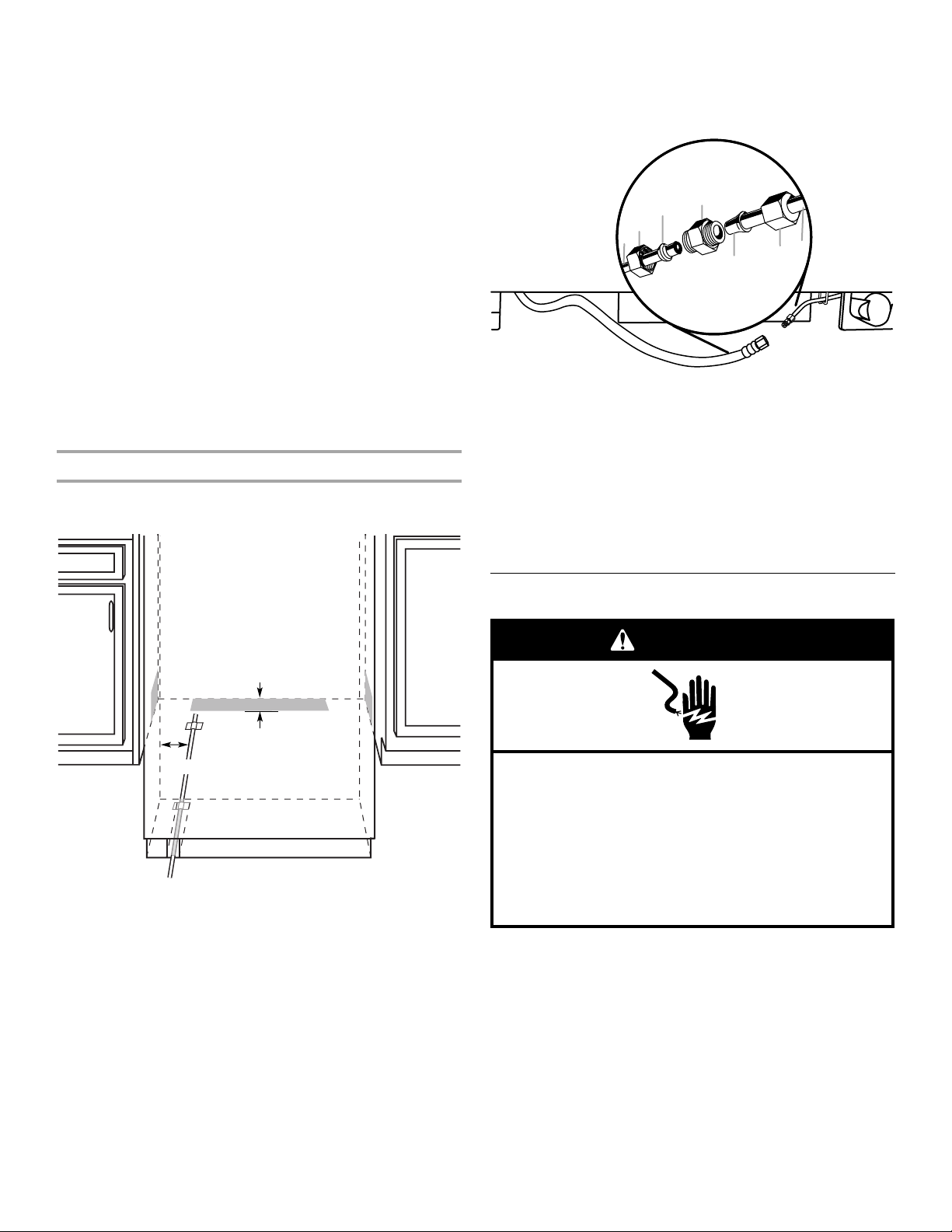
Connect to Refrigerator
Parts Supplied:
■ ¹⁄₄" to ¹⁄₄" (6.35 mm to 6.35 mm) male-to-male coupling
5. Connect the 7 ft (2.13 m) flexible codes approved water
supply line to the refrigerator.
NOTE: If the main water shutoff valve is behind the
refrigerator, a secondary water shutoff valve may be installed
in line with the water supply line at the front of the product.
A. Household water line
B. Nut (purchased)
C. Ferrule (purchased)
D. Coupling
6. Turn on the water supply valve and check all connections for
leaks.
7. Plug in the refrigerator or reconnect power.
8. Flush the water system. See “Water System Preparation.”
NOTE: Allow 24 hours to produce the first batch of ice.
Discard the first three batches of ice produced. Allow 3 days
to completely fill ice container.
E. Bulb
F. N u t
G. Refrigerator water tubing
Plug in Refrigerator
WARNING
1"
7"
(17.78 cm)
NOTE: The flexible, codes approved water supply line can
connect to the supply valve through the floor or through the side
cabinets, as indicated by the gray boxes above.
1. Unplug the refrigerator or disconnect power.
2. Connect the 7 ft (2.13 m) flexible codes approved water tube
to the water supply valve.
3. Flush the main water supply line to remove particles and air in
the water line. Allow enough flow so that water becomes clear.
4. Tape the 7 ft (2.13 m) flexible codes approved water supply
line to the floor, 7" (17.78 cm) from the left side of the
refrigerator. Tape along the length of the tubing, which will
allow it to pass beneath the refrigerator without interference.
NOTE: Allow a minimum of 26" (66.04 cm) of flexible codes
approved water supply line to be loose at the front of the
refrigerator for connecting to the refrigerator.
(2.54 cm)
Electrical Shock Hazard
Plug into a grounded 3 prong outlet.
Do not remove ground prong.
Do not use an adapter.
Do not use an extension cord.
Failure to follow these instructions can result in death,
fire, or electrical shock.
1. Set control switch at top of cabinet to the OFF position.
2. Plug into a grounded 3 prong outlet.
15
Move Refrigerator to Final Location
A
B
Level and Align Refrigerator
WARNING
Tip Over Hazard
Refrigerator is top heavy and tips easily when not
completely installed.
Keep doors taped closed until refrigerator is
completely installed.
Use two or more people to move and install
refrigerator.
Failure to do so can result in death or serious injury.
IMPORTANT:
■ To avoid floor damage, make sure levelers are raised (not
touching floor) and refrigerator is on rollers before moving.
■ Use the installation block, attached to the door hinge, as a
reference to make sure the refrigerator is pushed back far
enough into the opening, so that when the panels are installed
they will be flush with the adjacent cabinets.
■ After the refrigerator is leveled and aligned, remove the
installation block from the door hinge and use it to check the
spacing between the panels and adjacent cabinets.
NOTE: The installation block is designed to provide accurate
spacing for ³⁄₄" (1.9 cm), ³⁄₈" (9.53 mm) and ¹⁄₈" (3.18 mm).
WARNING
Tip Over Hazard
Refrigerator is top heavy and tips easily when not
completely installed.
Keep doors taped closed until refrigerator is
completely installed.
Use two or more people to move and install
refrigerator.
Failure to do so can result in death or serious injury.
IMPORTANT: All four leveling legs must contact the floor to
support and stabilize the full weight of refrigerator. Rollers are for
moving refrigerator and not for permanent support.
After moving the refrigerator to its final location:
1. Use a ⁵⁄₁₆" socket driver to turn the leveling bolts clockwise to
extend the legs to the floor as shown. The rollers should be off
the floor.
³⁄₄"
(1.9 cm)
³⁄₈"
(9.53 mm)
1. Place top of cardboard carton or plywood under refrigerator.
Remove dolly.
2. Move the refrigerator straight back and evenly into the
opening. Be sure that the water tubing is not kinked and the
power supply cord is on top of the refrigerator.
NOTE: If the power supply cord is behind the refrigerator, it
will not install properly.
3. Make sure the installation block is flush with the adjacent
cabinets.
NOTE: To achieve a flush installation, it is critical to verify a ³⁄₄"
(1.9 cm) depth from the front face of the adjacent cabinetry to
the refrigerator.
A
B
³⁄₄" (1.9 cm)
C
¹⁄₈"
(3.18 mm)
A B
A. Rear leveling bolt
B. Front leveling bolt
2. Adjust the leveling legs to level and align the refrigerator from
left to right and front to back so that the refrigerator is level
and aligned with the cabinets.
3. Continue adjusting all of the leveling legs to raise the
refrigerator until the top is within at least ¹⁄₄" (6.35 mm) of the
top soffit.
16
A. Adjacent cabinet or wall
B. Installation block
C. Face of refrigerator
NOTE: If an anti-tip board has been used, adjust the leveling
E
legs until the top of the refrigerator is within ¹⁄₄" (6.35 mm) of
the bottom of the anti-tip board as shown. Do not crush the
compressor cover.
BA
3. Slide the trim toward the back until it snaps into place.
C
¹⁄₄" (6 mm)
max.
2" (5 cm)
84"
(213.4 cm)
D
A. Center board
B. Two 2" x 4" x 32" (5 cm x 10 cm x 81 cm) boards
C. Attach to studs with six #8 x 3" (7.6 cm) screws
D. Compressor cover
E. Distance from bottom of anti-tip board to floor
¹⁄₄
" (6.35 mm) max. above refrigerator
IMPORTANT: Adjust in small increments to keep from
damaging the cabinet trim and causing problems with the
door alignment or top grille fit. To avoid damage to the cabinet
or leveling legs, do not apply more than 50 inch-pounds
(5.65 Nm) of torque to the leveling bolts. The leveling legs can
be extended to a maximum of 1¹⁄₄" (3.18 cm) below the rollers.
4. After leveling the refrigerator, use a straight edge or 4 foot
level going across the front of the refrigerator installation to
the cabinets to check that the refrigerator is still flush.
A
B
A. Cabinet side trim
B. Refrigerator door
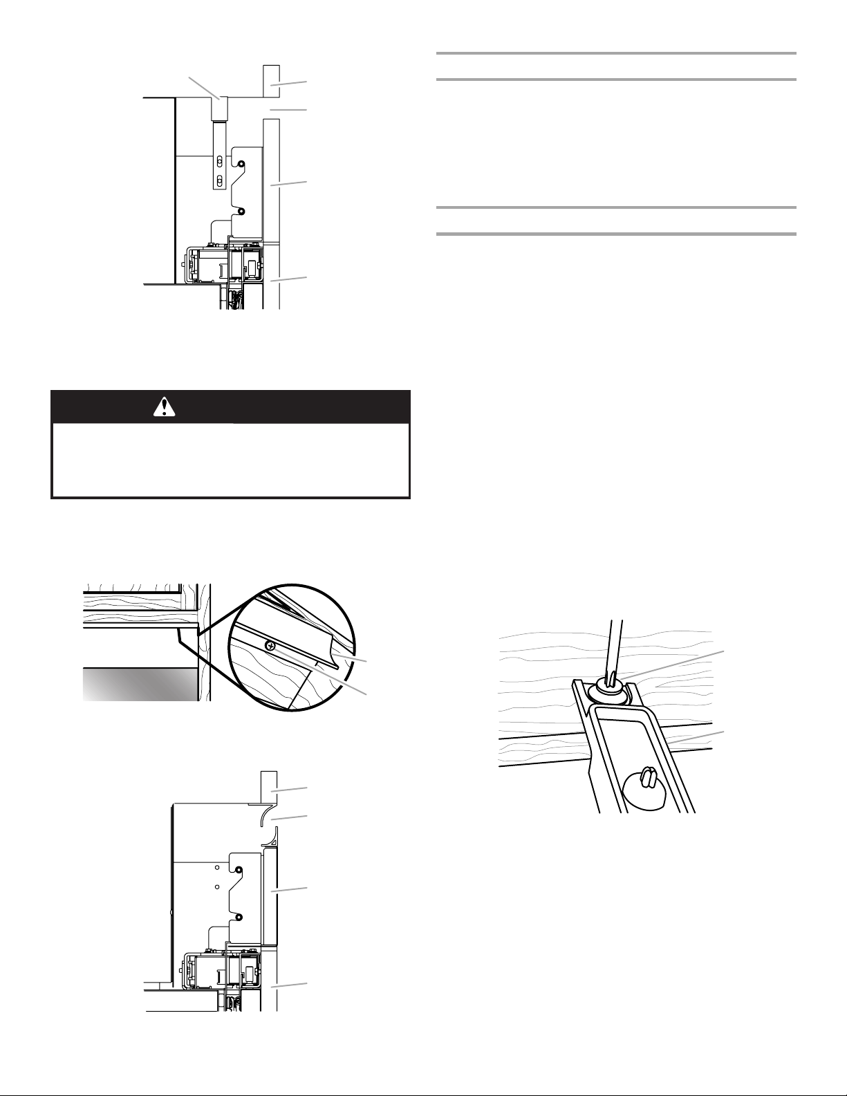
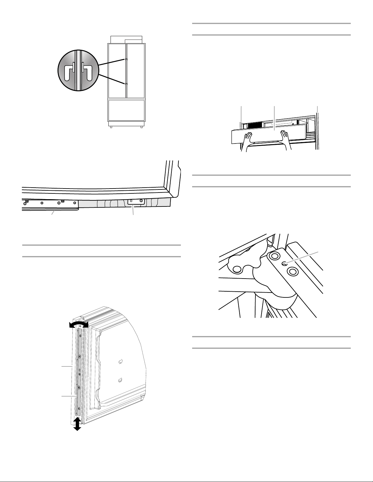
Install Top Grille Filler (standard installation only)
IMPORTANT: The grille panel height allows the necessary airflow
for refrigerator performance. The top grille filler hides the upper
compartment cover behind the top grille. If you choose to modify
the recommended grille panel dimensions, performance will be
compromised.
Custom Wood Panel Models
1. In the custom made (1" x width of grille panel) wood filler
piece, drill a hole
NOTE: Make sure the hole is centered in the 1" thickness of
the wood piece.
2. Using slotted hex head screws (provided), fasten an “L”
bracket to each end of the wood filler piece.
3. Using hex head blunt screws (provided), attach the “L”
brackets to the top grille mounting plates.
4. Adjust the “L” brackets, so that the wood filler piece is flush
with the bottom of the soffit. Completely tighten the screws.
¹¹⁄₁₆" from each edge.
Install Refrigerator and Overlay Panels
IMPORTANT: Jenn-Air is not responsible for the removal or
addition of molding or overlay panels that would not allow access
to the refrigerator for service.
Install Refrigerator to Adjacent Cabinets
1. Open the refrigerator door(s) and freezer drawer. On the hinge
side(s), locate the cabinet brackets in the space between the
door(s) and the refrigerator and the drawer and refrigerator.
2. Using the holes in the brackets as a template, predrill
pilot holes into the adjacent cabinet.
3. Using two round head screws (provided) for each bracket,
insert the screws through the cabinet brackets and into the
adjacent cabinetry to anchor the refrigerator.
4. Repeat steps 2 and 3 to anchor the other side of the
refrigerator to the adjacent cabinetry.
Install Cabinet Side Trims
Install cabinet side trims to hide the brackets fastening the
refrigerator to the adjacent cabinets.
1. Open the door(s) to a 90° angle.
2. With the lip edge of the trim toward the back wall, insert the
cabinet side trim between the side of the refrigerator and the
adjacent cabinetry.
NOTE: Keep the top edge of the trim piece flush with the top
of the refrigerator. Installing the trim higher than the
refrigerator top could cause damage to the trim when the door
is opened.
¹⁄₈" deep
A
B
C
A. Custom wood filler
B. “L” bracket
C. Grille mounting plate
17
Side View
B
C
D
A
B
A
B
C
D
A
B
A
E
A. Top grille filler
B. Soffit
C. Airflow
D. Grille panel
E. Door panel
Panel Kit Models
WARNING
Excessive Weight Hazard
Use two or more people to move and install panels.
Failure to do so can result in back or other injury.
1. Align top grille filler (provided in the door kit) with the bottom
edge of the soffit. Use as a template, and mark where to drill
the holes.
2. Using slotted hex head screws (provided), attach the top grille
filler to the soffit.
Drilling Templates (custom wood panels only)
IMPORTANT: The template can be used for either a ³⁄₈" (0.95 cm)
or a ¹⁄₈" (0.32 cm) reveal installation.
■ The drilling templates are double-sided.
■ On the template, locate the diagram of your refrigerator. Then,
follow the letters and colored arrows to correctly place the
drilling template on the panels.
■ The drilling holes are precut into the template.
Prepare Custom Overlay Panels
IMPORTANT:
■ The process for installing overlay panels on the refrigerator is
the same for both custom panels and panel kits.
■ The drilling templates are used only for custom wood overlay
panels.
■ The panels included in the panel kits are predrilled for the
mounting brackets only. See “Complete Installation” later in
this section, for instructions on drilling additional holes in the
door panels.
NOTE: For 36" model door panels which are right-hand swing
and left-hand swing specific use the following instructions:
■ Hinge on right-hand side - Use the holes, located on the
back side of the door panel, that are circled in red.
■ Hinge on left-hand side - Use the holes, located on the
back side of the door panel, that are circled in blue.
■ The film covering on stainless steel door panels must be
removed before installing brackets.
1. Place panels on a firm, flat surface with the front facing down.
2. Using the templates (provided), predrill ¹⁄₈" pilot holes into the
wood rails bordering the door(s), drawer and top grille panels.
Follow the instructions printed on the template.
3. Using the installation block as a guide for depth, screw the
door studs (provided) into the predrilled door panel (two door
studs per door).
Side View
18
A. Top grille filler
B. Hex head screw (provided)
A. Soffit
B. Airflow
C. Grille panel
D. Door panel
A. Door stud
B. Installation block
4. Insert the hex head pointed screws (provided) into the wood at
the top of the door panels where they were predrilled.
NOTE: It is critical to use the ⁵⁄₈" screw, the longest length
provided, to attach the bracket to the top of the door panel.
These hex head pointed screws are used only to attach this
mounting bracket.
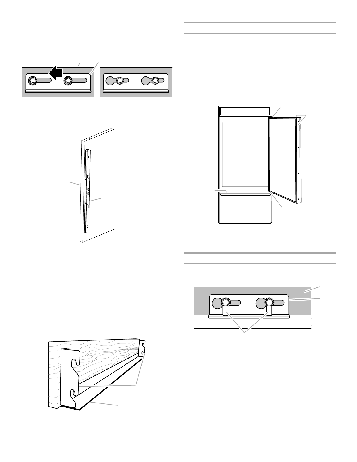
5. Attach a mounting bracket to the top edge of the door panel(s)
B
A
B
by placing the large ends of the keyhole slots over the screws
and sliding the bracket so that the screws are centered in the
slots.
NOTE: Start with the screws in the center of the slots as
shown, then move the door panel, as necessary, to align.
AB
Remove Trim Pieces
1. Remove all tape and door bracing from the refrigerator and
freezer doors.
2. Open the refrigerator and freezer doors.
3. Remove the hinge cover pieces from the top and bottom of
the door to expose the holes in the hinges.
NOTES:
■ It is not necessary to remove the hinge side trims as they
will not interfere with the installation
■ Leave the freezer drawer trims in place for installation.
A. Door panel B. Mounting bracket
6. Using the Phillips head flat screws (provided), fasten a
mounting bracket to each side of the drawer panel, as shown.
A
B
A. Drawer panel
B. Drawer panel mounting bracket
7. Using the slotted hex head screws provided, attach a
mounting bracket to each side of the grille panel.
NOTES:
■ See the Parts Provided insert sheet to select the brackets
designated for your installation.
■ Use the Integrated Grille brackets for an Integrated
Installation with a full height grille.
■ Use the Standard Grille brackets for a Standard
Installation with a flush grille, as shown.
8. Using round head screws (provided), attach the grille trim
piece to the bottom of the grill panel.
A
C
A
A. Hinge cover pieces
B. Handle-side door trim
C. Drawer trim
Install Door Panels
1. Lower the panel mounting bracket onto the adjustment pins at
the top of the door.
C
A. Door panel
B. Mounting bracket
C. Adjustment pins
2. Slide the studs, on the back side of the door panel, into the
“J” pockets in the front of the door.
A. Top grille brackets
B. Grille trim piece
A
B
19
NOTE: French door models, repeat steps 1 and 2 to install the
second door panel.
3. Using a slotted hex head screw (provided), attach the
mounting bracket (factory installed), located at the bottom of
the refrigerator door(s), to the respective door panel(s). Do not
fully tighten the screw.
A B
A. Bottom hinge
B. Mounting bracket
Install Top Grille Panel
Standard Installation - Flush Grille
1. Hook the panel brackets onto the mounting bolts extending
from the top of the refrigerator.
2. Pull the grille panel down slightly to lock into place.
Integrated Installation - Full Height Grille
1. Align the bracket with the mounting bolts.
2. Push the grille panel forward until the bracket snaps into
place.
B BA
A. Top grille panel
B. Cabinet sides
Door Swing Adjustment
It may be necessary to adjust the swing of the door(s). Make sure
the refrigerator door(s) can open freely. If the door(s) opens too
wide, install the door stop pin (provided).
1. Hold the door open to a position that is less than 90°.
2. Insert the door stop pin into the top hinge in the hole shown.
3. Using a ⁵⁄₃₂" Allen wrench, tighten the door stop pin.
Install Drawer Panel
1. Align the slots in the mounting brackets, located on each side
of the drawer panel, with the holes that go through the drawer
trim and into the drawer.
2. Using Phillips head flat screws (provided), attach the brackets
to the drawer.
3. Move the drawer panel up and down or from side to side to
align. Do not fully tighten the screws.
A
B
A
A. Door stop pin hole
Complete Installation
1. Use the installation block to measure the gaps between the
overlay panels and adjacent cabinets.
20
A. Drawer overlay panel
B. Panel mounting bracket

■ Stainless steel panels require a ³⁄₈" (0.95 cm) gap between
C
A
B
the stainless panel and the cabinets and a ¹⁄₈" (0.32 cm)
gap between the freezer and refrigerator door, and the
doors and top grille.
A
B
A. Adjacent cabinet
B. Installation block
C. Overlay panel on door
2. Adjust the panel to achieve the required spacing, or to align.
IMPORTANT: If adjustments are needed, adjust the panel not
the door.
■ Slide the overlay panel from side to side in the keyhole
slot.
■ Use an Allen wrench to raise or lower the adjustment pins
which allows the door panel to swivel.
5. If necessary, adjust the drawer panel to align and fully tighten
all drawer panel screws.
A
B
A. Drawer overlay panel
B. Panel mounting bracket
6. Using slotted hex head screws (provided) for each side, attach
the door panels to the hinge-side door trims.
7. Using Phillips head flat screws (provided), install the handle
side door trim.
8. Completely tighten the screws attaching the mounting
brackets, located at the bottom of the doors, to the overlay
panels.
9. Reinstall the top door trim and hinge cover.
10. Snap the adjustment pin cover (provided) into place.
C
A. Door panel
B. Mounting bracket
C. Adjustment pins
3. Predrill ¹⁄₈" pilot holes in the door panel(s) through the open
holes in both the bottom and top hinges.
4. Using the slotted hex head screws (provided), attach the top
and bottom hinges to the door panels. Fully tighten all door
panel screws.
NOTE: For 36" models, there is an additional bracket at the
top to fasten the overlay panel to the door. Insert the screws
through the bracket into the door panel.
BA
DC E
A. Top hinge
B. Adjustable mounting bracket
C. Holes for screws
D. Adjustment door pins
E. 36" Models only -
Holes for screws
Install Handles
(Panel Kit Models Only)
IMPORTANT: Install the handles after the door panels have been
installed.
Tools Needed: ³⁄₃₂" Allen wrench
1. Locate the holes in the door panels where the handle
mounting studs are to be installed.
2. Fasten the handle mounting studs to the door panels.
3. Install the handles to the handle mounting studs and tighten
the setscrews.
NOTE: Depending on the handle, the setscrews may be either
a separate part, or a component of the mounting stud.
Install Base Grille
There are two pieces to the base grille to allow for a custom fit: the
base grille itself and the skirt. The skirt can be added to the base
grille in order to extend it all the way to the floor.
1. To see whether the skirt is needed, place the base grille into
position. Do not attach the base grille to the refrigerator.
Measure the distance between the bottom of the base grille
and the floor. The gap must be a minimum of ¹⁄₂" (1.27 cm) in
order to add the skirt.
NOTE: If the gap measures less than ¹⁄₂" (1.27 cm), skip
steps 3 and 4 of the instructions, and install the base grille
only.
2. Remove the film from the base grille.
21

3. Snap the skirt onto the base grille.
A
B
A. Base grille
B. Skirt
4. Trim the skirt by scoring the proper “V” groove with a utility
knife. Break the skirt at the score line.
4. Install the shelves and bins in the refrigerator and freezer
compartments.
5. The controls are preset at the factory to the midpoint setting.
Check that the compressor is operating properly and that all
the lights are working.
6. Flush the water system before use. See “Water System
Preparation.”
To get the most efficient use from your new built-in refrigerator,
read the Use & Care Guide. Keep Installation Instructions and Use
& Care Guide near the built-in refrigerator for easy reference.
Water System Preparation
Please read before using the water system.
Immediately after installation, follow the steps below to make sure
that the water system is properly cleaned.
1. Open the freezer door and turn off the ice maker. For Style 1,
lift up the wire shutoff arm as shown. For Style 2, move the
switch to the OFF (right) setting as shown. The On/Off switch
is located on the top right side of the freezer compartment.
Style 1 – Non-Dispenser Models
Style 2 – Dispenser Models
A
A. “V” groove
5. Using the two screws, attach the base grille assembly to the
refrigerator as shown.
NOTE: Drive in the right side screw first.
A
A. Screws (2)
Complete Installation
1. Turn the water supply line valve to the “Open” position.
2. Turn the refrigerator switch to the ON position. See “Power
On/Off Switch” in the Use & Care Guide for instructions. Wait
a few minutes. Check the water line connections for leaks.
3. Remove all boxes, parts packages and packing materials from
the interior of the refrigerator. See the “Cleaning” section in
the Use & Care Guide for instructions. Remove the film and
cardboard from the grille and doors or door frame, depending
on your model.
NOTE: If your model has a base grille filter system, make sure the
base grille filter is properly installed and the cap is in the horizontal
position.
Do not use with water that is microbiologically unsafe or
of unknown quality without adequate disinfection before
or after the system. Systems certified for cyst reduction
may be used on disinfected waters that may contain
filterable cysts.
2. Use a sturdy container to depress and hold the water
dispenser lever for 5 seconds, then release it for 5 seconds.
Repeat until water begins to flow. Once water begins to flow,
continue depressing and releasing the dispenser lever
(5 seconds on, 5 seconds off) for an additional 2 minutes. This
will flush air from the filter and water dispensing system.
Additional flushing may be required in some households.
NOTE: As air is cleared from the system, water may spurt out
of the dispenser.
3. Open the freezer door and turn on the ice maker. For Style 1,
lower the wire shutoff arm. For Style 2, move the switch to the
ON (left) position.
■ Allow 24 hours to produce the first batch of ice.
■ Discard the first three batches of ice produced.
■ Depending on your model, you may want to select the
maximum ice feature to increase the production of ice.
22

SEGURIDAD DEL REFRIGERADOR
Su seguridad y la seguridad de los demás es muy importante.
Hemos incluido muchos mensajes importantes de seguridad en este manual y en su electrodoméstico. Lea y obedezca siempre
todos los mensajes de seguridad.
Este es el símbolo de advertencia de seguridad.
Este símbolo le llama la atención sobre peligros potenciales que pueden ocasionar la muerte o una lesión a
usted y a los demás.
Todos los mensajes de seguridad irán a continuación del símbolo de advertencia de seguridad y de la palabra
“PELIGRO” o “ADVERTENCIA”. Estas palabras significan:
PELIGRO
ADVERTENCIA
Todos los mensajes de seguridad le dirán el peligro potencial, le dirán cómo reducir las posibilidades de sufrir una lesión y lo que
puede suceder si no se siguen las instrucciones.
Si no sigue las instrucciones de inmediato, usted puede
morir o sufrir una lesión grave.
Si no sigue las instrucciones, usted puede morir o sufrir
una lesión grave.
ADVERTENCIA
Peligro de Vuelco
El refrigerador puede volcarse cuando está siendo
instalado debido a que la parte superior es pesada.
Mantenga las puertas cerradas con cinta hasta que el
refrigerador esté completamente instalado.
Use dos o más personas para mover e instalar el
refrigerador.
No seguir estas instrucciones puede ocasionar
la muerte o herida seria.
23

MODELOS DE 36"
Diseño incorporado
Presenta paneles y piezas hechos a la medida provistos por el
fabricante de armarios, para dar una apariencia perfecta,
diseñada para armonizar con los armarios de cocina existentes.
Números de modelos base: JB36NXFXLW, JB36NXFXRW
Diseño de acero inoxidable Pro-Style
Equipado con puertas con cobertura de acero inoxidable y manijas
con grabado en forma de diamante Pro-Style
Números de modelos base: JB36NXFXLW, JB36NXFXRW
Número de modelo del juego: JPK36BNXWPS
®
®
.
Juegos de manijas para puertas
Euro-Style y Pro-Style
Todas las piezas de fábrica están disponibles a través de su
distribuidor de Jenn-Air o llamando a Jenn-Air al 1-800-JENNAIR
(1-800-536-6247). En Canadá, llame al 1-800-807-6777.
Siga las instrucciones del juego para la instalación de las manijas de
las puertas.
Diseño Pro-Style
Diseño Euro-Style de acero inoxidable - BM W10250635
®
de acero inoxidable - BM W10250641
®
Diseño Euro-Style de acero inoxidable
Equipado con puertas con cobertura de acero inoxidable y las
nuevas manijas Euro-Style, diseñadas para complementar los
electrodomésticos de cocina Jenn-Air Euro kitchen suite o para
realzar la decoración de cualquier cocina.
Números de modelos base: JB36NXFXLW, JB36NXFXRW
Número de modelo del juego: JPK36BNXWES
24
MODELOS DE DOS PUERTAS CON CONGELADOR
EN LA PARTE INFERIOR, DE 42"
Diseño incorporado
Presenta paneles y piezas hechos a la medida provistos por el
fabricante de armarios, para dar una apariencia perfecta,
diseñada para armonizar con los armarios de cocina existentes.
Números de modelos base: JF42NXFXDW
Diseño de acero inoxidable Pro-Style
Equipado con puertas con cobertura de acero inoxidable y manijas
con grabado en forma de diamante Pro-Style
Números de modelos base: JF42NXFXDW
Número de modelo del juego: JPK42FNXWPS
®
®
.
Juegos de manijas para puertas
Euro-Style y Pro-Style
Todas las piezas de fábrica están disponibles a través de su
distribuidor de Jenn-Air o llamando a Jenn-Air al 1-800-JENNAIR
(1-800-536-6247). En Canadá, llame al 1-800-807-6777.
Siga las instrucciones del juego para la instalación de las manijas de
las puertas.
Diseño Pro-Style
Diseño Euro-Style de acero inoxidable - FDBM W10250636
®
de acero inoxidable - FDBM W10250642
®
Diseño Euro-Style de acero inoxidable
Equipado con puertas con cobertura de acero inoxidable y las
nuevas manijas Euro-Style, diseñadas para complementar los
electrodomésticos de cocina Jenn-Air Euro kitchen suite o para
realzar la decoración de cualquier cocina.
Números de modelos base: JF42NXFXDW
Número de modelo del juego: JPK42FNXWES
25

REQUISITOS DE INSTALACIÓN
Piezas y herramientas
IMPORTANTE:
■ Instalador: Deje las Instrucciones de instalación con el
propietario.
■ Propietario: Conserve las Instrucciones de instalación para
referencia futura. Guarde estas Instrucciones de instalación
para tenerlas a disposición del inspector de electricidad local.
HERRAMIENTAS NECESARIAS:
Reúna las herramientas y piezas necesarias antes de comenzar la
instalación. Lea y siga las instrucciones provistas con cualquiera
de las herramientas enlistadas aquí.
■ Taladro inalámbrico
■ Brocas
■ Dos llaves ajustables
■ Destornillador Phillips
■ Nivel pequeño
■ Plataforma rodante para
electrodomésticos
■ Llave Allen de ³⁄₃₂"
(sólo para los juegos de
paneles)
PIEZAS NECESARIAS:
■ 6 tornillos de madera #8 x 3" (7,6 cm) (pudieran necesitarse
tornillos más largos)
■ Uno o dos tableros de madera de 2" x 4" x 32" (5 cm x 10 cm x
81 cm)
■ Diseño incorporado - Consulte con un fabricante de armarios
o carpintero calificado para hacer paneles de madera a la
medida. Vea “Paneles recubiertos a la medida para Integrated
Series”.
Diseño de acero inoxidable – El juego de paneles se envía con
el refrigerador.
■ Tubería de suministro de agua flexible aprobada por los
códigos, una férula, una unión y un accesorio de compresión
de ¹⁄₄" (6,35 mm).
■ Llave para tuercas de ¹¹⁄₃₂"
■ Llaves de boca de ³⁄₈" y ¹⁄₂"
■ Llave Allen de ⁵⁄₃₂" y ³⁄₁₆"
■ Llaves de cubo de ¹⁄₄" y ⁵⁄₁₆"
■ Cinta para medir
■ Cuchillo para uso general
■ Cinta adhesiva (para pintores)
Requisitos de ubicación
ADVERTENCIA
Peligro de Explosión
Mantenga los materiales y vapores inflamables,
tales como gasolina, alejados del refrigerador.
No seguir esta instrucción puede ocasionar la muerte,
explosión, o incendio.
IMPORTANTE:
■ Observe todos los códigos y reglamentos aplicables.
■ No se recomienda instalar el refrigerador cerca de un horno,
radiador u otra fuente de calor.
■ No instale en un lugar donde la temperatura puede ser menor
de 55°F (13°C).
■ El piso debe soportar el peso del refrigerador: más de 600 lb
(272 kg), paneles de puerta y contenido del refrigerador.
■ La altura del techo deberá permitir que haya un arco de
vuelco lateral. Vea “Arco de vuelco”.
■ La ubicación debe permitir que la puerta se abra totalmente.
Vea “Medidas de oscilación de las puertas”.
■ La ubicación debe permitir que se quite la rejilla superior. Vea
“Medidas de la abertura”.
Dimensiones de la abertura
■ Deberá instalarse un sofito o armario de pared 84" (213,4 cm)
por encima del piso. Si el sofito sólido está a una altura de
más de 84" (213,4 cm) o no hay ninguno disponible, el
refrigerador deberá tener un soporte.
Si se necesitan tableros anti-vuelco, deberán estar sujetos a
los pies derechos de la pared posterior, de modo que haya
una distancia de 84" (213,4 cm) desde la base del tablero antivuelco hasta el piso. Vea “Cómo instalar los tableros antivuelco” para obtener más información.
■ Para una instalación completamente incorporada, se
necesitará un espacio abierto mínimo de 6" (15,24 cm) por
encima del refrigerador. Vea “Instalación completamente
incorporada”. Se necesitarán tableros anti-vuelco. Vea “Cómo
instalar los tableros anti-vuelco” para obtener más
información.
■ El ancho de la abertura de lado a lado deberá ser el
especificado para su modelo, por lo menos a una distancia de
2" (5,08 cm) hacia atrás desde la cara del armario. Si la
abertura no cumple con este requisito, deberá hacer
modificaciones.
■ Un contacto de tres terminales con conexión a tierra debe ser
ubicado a no más de 4" (10,2 cm) del lado derecho de los
armarios o del panel del extremo. Vea “Requisitos eléctricos”
para obtener información adicional.
26

■ El cierre del agua deberá estar localizado en el armario
inferior, a cualquier lado del refrigerador o en algún otro lugar
de fácil acceso. Si la válvula de cierre del agua no está en los
armarios, la tubería para la línea del agua puede llegar a través
del piso. Vea “Requisitos del suministro de agua” para
obtener más información.
80" - 90"
(203-229 cm)
84" (213,4 cm)
a la base del sofito sólido
4"
(10,2 cm)
Requisitos eléctricos
ADVERTENCIA
Peligro de Choque Eléctrico
Conecte a un contacto de pared de conexión a tierra de
3 terminales.
No quite la terminal de conexión a tierra.
No use un adaptador.
No use un cable eléctrico de extensión.
No seguir estas instrucciones puede ocasionar
la muerte, incendio o choque eléctrico.
77"
(196 cm)
A
Ancho
(vea el cuadro siguiente)
B
1"
6"
(15,2 cm)
(2,54 cm)
6"
(15,2 cm)
Modelo Ancho A (como se muestra arriba)
36
42
36" (91,4 cm)
42" (106,7 cm)
Antes de mover el refrigerador a su posición definitiva, es
importante asegurarse que Ud. tiene la conexión eléctrica
adecuada.
Método de conexión a tierra recomendado
Se requiere una fuente de energía eléctrica de 115 Voltios, 60 Hz.,
CA solamente y con fusibles de 15 ó 20 amp, debidamente
conectada a tierra. Se recomienda que se use un circuito
separado sólo para su refrigerador. Use un tomacorriente que no
se puede apagar con un interruptor. No use un cable eléctrico de
extensión.
IMPORTANTE: Si este producto está conectado a un
tomacorriente protegido por un interruptor del circuito de falla
eléctrica de puesta a tierra (GFCI - Ground Fault Circuit
Interrupter), puede ocurrir un disparo brusco del suministro de
corriente, lo que resultará en una pérdida de enfriamiento. Esto
puede afectar la calidad y el sabor de los alimentos. Si ha
ocurrido un disparo brusco, y el alimento aparenta estar en malas
condiciones, deshágase del mismo.
NOTA: Antes de realizar cualquier tipo de instalación, limpieza o
quitar un foco, quite la rejilla superior y ponga el interruptor
principal de energía en la posición OFF (Apagado) o desconecte
el suministro de energía eléctrica en la caja de disyuntores.
Cuando haya terminado, ENCIENDA el interruptor principal de
energía o reconecte el suministro de energía en la caja de
disyuntores. Luego vuelva a ajustar el control en la posición
deseada.
Tipo de instalación Profundidad B (como se
muestra arriba)
Alineamiento estándar
25"(63,5 cm) como mínimo
(instalación nueva)
Instalaciones para adiciones
24"(60,9 cm) como mínimo
posteriores
IMPORTANTE:
■ El piso que está debajo del refrigerador deberá estar al
mismo nivel que la habitación. El frente de los armarios
debe estar a plomo.
■ El ancho de la abertura (Ancho A) deberá ser el
especificado para su modelo, por lo menos a una
distancia de 2" (5,08 cm) hacia atrás desde la cara del
armario. Si la abertura no cumple con este requisito,
deberá hacer modificaciones.
27
Requisitos del suministro de agua
■ Todas las instalaciones deben hacerse de acuerdo a los
requerimientos locales de plomería.
■ La línea de suministro de agua deberá pasar a través del piso,
en el área sombreada de gris, como se muestra.
■ El cierre del agua deberá estar localizado en el armario
inferior, a cualquier lado del refrigerador o en algún otro lugar
de fácil acceso. Recomendamos el lado derecho.
NOTA: No habrá espacio suficiente para lograr una instalación
alineada si la válvula de cierre de agua está ubicada en la
pared que está detrás del refrigerador.
6"
(15,2 cm)
■ Deje que se vuelva a llenar el tanque de almacenaje del
sistema de ósmosis inversa después del uso intenso.
■ Si su refrigerador tiene un filtro de agua, se podrá reducir la
presión aún más si se usa en conjunto con un sistema de
ósmosis inversa. Quite el cartucho del filtro de agua.
Si tiene preguntas acerca de la presión del agua, llame a un
plomero competente autorizado.
Dimensiones del producto
IMPORTANTE:
■ La profundidad desde la cara frontal de las puertas hasta la
parte posterior de la carcasa del refrigerador es de 24"
(60,96 cm) sin paneles.
■ El cable de suministro de energía es de 84" (213 cm) de largo.
■ La línea de suministro de agua está ubicada en el frente del
refrigerador.
36", congelador en la parte inferior
Vista superior
6"
(15,2 cm)
■ Deberá taladrarse un orificio de ½" (12,7 mm) para la plomería
1"
(2,54 cm)
6"
(15,2 cm)
a por lo menos 6" (15,2 cm) del lado derecho o izquierdo del
armario o panel. En el piso, el orificio no debe estar a más de
1" (2,54 cm) de la pared trasera. Vea “Conexión del suministro
de agua”.
■ Si necesita tubería adicional, use tuberías de cobre y revise si
hay fugas. Instale la tubería de cobre sólo en áreas donde la
temperatura vaya a permanecer por encima del punto de
congelación.
■ No use una válvula perforadora o una válvula de montura de
³⁄₁₆" (4,76 mm) que reduce el flujo de agua y se obstruye con
más facilidad.
NOTA: El distribuidor de su refrigerador tiene disponible un
juego con una válvula de cierre tipo montura de
¹⁄₄" (6,35 mm),
una unión y tubería de cobre. Antes de comprar, asegúrese
que la válvula tipo montura cumpla con los códigos de
plomería de su localidad.
Presión del agua
Se necesita un suministro de agua fría con presión de agua entre
30 y 120 lbs/pulg² (207 y 827 kPa) para hacer funcionar el
despachador de agua y la fábrica de hielo. Si usted tiene
preguntas acerca de la presión de agua, llame a un plomero
competente autorizado.
Suministro de agua de ósmosis inversa
IMPORTANTE: La presión del suministro de agua que sale de un
sistema de ósmosis inversa y va a la válvula de entrada de agua
del refrigerador necesitará ser entre 30 y 120 lbs/pulg²
(207 y 827 kPa).
Si se conecta un sistema de filtración de agua de ósmosis inversa
al suministro de agua fría, la presión de agua al sistema de
ósmosis inversa necesitará ser de un mínimo de 40 a 60 lbs/pulg²
(276 a 414 kPa).
Si la presión del agua al sistema de ósmosis inversa es menor de
40 a 60 lbs/pulg² (276 a 414 kPa):
■ Fíjese si el filtro de sedimentos en el sistema de ósmosis
inversa está bloqueado y reemplácelo si fuera necesario.
24"
(61,0 cm)
35³⁄₄"
(90,8 cm)
Vista frontal
■ Las medidas de ancho fueron tomadas desde el borde de la
bisagra hasta el borde del sujetador.
35³⁄₄"
(90,8 cm)
84"
(213,4 cm)
28

42", dos puertas, congelador en la parte inferior
Vista superior
24"
(61,0 cm)
41³⁄₄"
(106,1 cm)
Vista frontal
■ Las medidas de anchura fueron tomadas desde un extremo
de la bisagra al otro extremo de la bisagra.
41³⁄₄"
(106,1 cm)
Arco de vuelco lateral (modelos de 36" [91,4 cm])
A
A. 88
⁷⁄₈
" (225,7 cm)
Arco de vuelco lateral (modelos de 42" [106,7 cm])
84"
(213,4 cm)
Arco de vuelco
Asegúrese de que el techo sea lo suficientemente alto para
colocar el refrigerador en posición vertical cuando se mueva a su
lugar.
■ Si se utiliza una plataforma rodante, se debe agregar la altura
de sus ruedas al arco de vuelco.
■ Si es necesario, se puede reducir el arco de vuelco. Vea
“Cómo reducir el arco de vuelco”.
NOTA: Incline solamente de lado.
A
³⁄₈
" (232,1 cm)
A. 91
Medidas de oscilación de las puertas
La ubicación debe permitir que ambas puertas se abran a un
mínimo de 90°. Deje un espacio mínimo de 4½" (11,4 cm) entre el
lado del refrigerador y una esquina de la pared.
NOTA: Es posible que se necesite más espacio si va a utilizar
paneles recubiertos, manijas a la medida o manijas extendidas.
BA C D
90˚
110˚
Modelo A B C D
36 36"
(91,4 cm)
42 42"
(106,7 cm)
39³⁄₄"
(101,0 cm)
42"
(106,7 cm)
90˚
110˚
45³⁄₈"
(115,3 cm)
48⁵⁄₈
(123,5 cm)
46³⁄₄"
(118,8 cm)
50¹⁄₄
(127,6 cm)
29

Opciones para la instalación
del armario y los paneles
Profundidad del armario - 25" (63,5 cm)
Armarios con marcos
Vista superior - Recubierto
Profundidad del armario - 24" (60,9 cm)
Armarios con marcos
Vista superior
E
D
C
E
D
C
A. Puerta del refrigerador
B. Panel recubierto
C.Moldura lateral
A B
D. Armario adyacente
E. Soporte de la rejilla
A B
A. Puerta del refrigerador
B. Panel recubierto
C. Moldura lateral
Vista superior - Recuadro
A B
A. Puerta del refrigerador
B. Panel recubierto
C. Moldura lateral
Armarios sin marco
A B
A. Puerta del refrigerador
B. Panel recubierto
C. Moldura lateral
D. Armario adyacente
E. Soporte de la rejilla
E
D
C
D. Armario adyacente
E. Soporte de la rejilla
E
D
C
D. Armario adyacente
E. Soporte de la rejilla
Armarios sin marco
Vista superior
E
D
C
A B
A. Puerta del refrigerador
B. Panel recubierto
C. Moldura lateral
D. Armario adyacente
E. Soporte de la rejilla
Requisitos para la instalación
completamente incorporada
El refrigerador puede instalarse completamente incorporado si los
armarios adyacentes cumplen con los requisitos de ventilación y
flujo de aire, críticos para el funcionamiento del mismo.
IMPORTANTE:
■ Tanto las instalaciones estándar como las instalaciones
incorporadas por completo pueden lograrse con una abertura
de una profundidad de 24" (60,9 cm) o 25" (63,5 cm).
■ Se usará una rejilla de altura completa para lograr una
instalación completamente incorporada. Use el soporte
incorporado (provisto) para fijar la rejilla de altura completa.
NOTA: No se necesitará una cubierta para la rejilla superior
con la rejilla de altura completa.
Soporte incorporado de rejilla
30

Instalación completamente incorporada - Vista lateral
A
B
C
D
Opción 2 - Frente falso (solamente la cara del armario)
6" (15,24 cm)
min.
A. Frente falso (opcional)
B. Flujo de aire
C. Rejilla de altura completa
D. Panel de la puerta
Requisitos de flujo de aire y ventilación
Para instalaciones completamente incorporadas se necesitará un
espacio abierto mínimo de 6" (15,24 cm) por encima del
refrigerador. El espacio no deberá estar obstruido de ninguna
manera, incluyendo los sofitos.
Opción 1 - Abierto hacia el techo
6" (15,24 cm)
min.
Paneles recubiertos a la medida
Los paneles a la medida recubiertos le permiten armonizar el
exterior de su refrigerador con la decoración de la cocina y usar
las manijas a la medida para mayor flexibilidad en el diseño.
En algunos casos, su fabricante de armarios puede elegir trabajar
con un panel trazado para las diferentes medidas. Siga estas
medidas de panel e instrucciones de instalación para asegurarse
de que los paneles a la medida recubiertos encajarán
adecuadamente.
IMPORTANTE:
■ Para los modelos de 36" (91,4 cm), el peso del panel
recubierto de la puerta del refrigerador no puede ser mayor de
60 lb (27,2 kg), y el peso del panel recubierto del cajón del
congelador no puede ser mayor de 25 lb (11,3 kg).
■ Para los modelos de 42" (106,7 cm), el peso del panel
recubierto de la puerta del refrigerador no puede ser mayor de
40 lb (18,1 kg), y el peso del panel recubierto del cajón del
congelador no puede ser mayor de 30 lb (13,6 kg).
■ El peso del panel recubierto de la rejilla superior no puede ser
mayor de 7 lb (3,2 kg) para ambos modelos.
■ El espesor necesario para todos los paneles es de ³⁄₄"
(1,91 cm).
■ Esta instalación no requiere paneles de cubierta ni de soporte.
31

Dimensiones de los paneles recubiertos
Modelo de 36" (91,4 cm)
Paneles de la puerta y del cajón
52³⁄₈"
(133,03 cm)
20¹⁄₂"
(52,07 cm)
PANEL DE LA PUERTA DEL
REFRIGERADOR
Peso máximo: 60 lbs (27,2 kg)
PANEL DEL CAJÓN DEL
CONGELADOR
Peso máximo: 25 lbs (11,34 kg)
Modelo de 42" (106,7 cm)
Paneles de la puerta y del cajón
A
52³⁄₈"
(133,03 cm)
B
20¹⁄₂"
(52,07 cm)
A
PANEL DE LA
PUERTA DEL
REFRIGERADOR
Peso máximo:
40 lbs (18,14 kg)
B
PANEL DEL CAJÓN DEL
CONGELADOR
Peso máximo: 30 lbs (13,6 kg)
A
PANEL DE LA
PUERTA DEL
REFRIGERADOR
Peso máximo:
40 lbs (18,14 kg)
CUIDADO
Peligro de pellizcos
Si se instalan los paneles de la puerta con un espacio menor
de ³⁄₈" (0,95 cm) entre el panel de la puerta y el armario
adyacente, aumentará el riesgo de pellizcos potenciales.
Modelo Congelador en la parte inferior, de 36"
Mocheta ³⁄₈" ¹⁄₈"
A 35¹⁄₄" (89,54 cm) 35³⁄₄" (90,81 cm)
B 35¹⁄₄" (89,54 cm) 35³⁄₄" (90,81 cm)
CUIDADO
Peligro de pellizcos
Si se instalan los paneles de la puerta con un espacio menor
de ³⁄₈" (0,95 cm) entre el panel de la puerta y el armario
adyacente, aumentará el riesgo de pellizcos potenciales.
Modelo Dos puertas, congelador en la parte inferior,
de 42"
Mocheta ³⁄₈" ¹⁄₈"
A 20 ⁹⁄₁₆" (52,23 cm) 20¹³⁄₁₆" (52,86 cm)
B 41¹⁄₄" (104,76 cm) 41³⁄₄" (106,05 cm)
Panel de la rejilla
Instalación incorporada - Rejilla de altura completa
C
⁵⁄₈"
6
(16,83 cm)
Modelo 36 42
Moche-
³⁄₈" ¹⁄₈" ³⁄₈" ¹⁄₈"
ta
C 35¹⁄₄"
(89,54 cm)
Panel para la rejilla superior
35³⁄₄"
(90,81 cm)
41¹⁄₄"
(104,76 cm)
41³⁄₄"
(106,05 cm)
32

Instalación estándar - Rejilla alineada
D
1" (2,54 cm)
Cubierta de la rejilla superior
Cómo introducir el refrigerador
en la casa
E
³⁄₄"
5
(14,55 cm)
Modelo 36 42
Mocheta
D 35¹⁄₄"
E 35¹⁄₄"
IMPORTANTE: La altura del panel de la rejilla, que se muestra en
la ilustración de la Instalación estándar - Rejilla alineada, permite
un espacio de aire que es crítico para el funcionamiento del
refrigerador.
³⁄₈" ¹⁄₈" ³⁄₈" ¹⁄₈"
(89,54 cm)
(89,54 cm)
Panel para la rejilla superior
35³⁄₄"
(90,81 cm)
35³⁄₄"
(90,81 cm)
41¹⁄₄"
(104,76 cm)
41¹⁄₄"
(104,76 cm)
41³⁄₄"
(106,05 cm)
41³⁄₄"
(106,05 cm)
INSTRUCCIONES DE
INSTALACIÓN
Desempaque el refrigerador
ADVERTENCIA
ADVERTENCIA
Peligro de Vuelco
El refrigerador puede volcarse cuando está siendo
instalado debido a que la parte superior es pesada.
Mantenga las puertas cerradas con cinta hasta que el
refrigerador esté completamente instalado.
Use dos o más personas para mover e instalar el
refrigerador.
No seguir estas instrucciones puede ocasionar
la muerte o herida seria.
1. Coloque una plataforma rodante para electrodomésticos
debajo del lado izquierdo del refrigerador, como se muestra.
Coloque los esquinales de los materiales de empaque sobre
las cubiertas, según sea necesario. Apriete el fleje lentamente.
Peligro de Vuelco
El refrigerador puede volcarse cuando está siendo
instalado debido a que la parte superior es pesada.
Mantenga las puertas cerradas con cinta hasta que el
refrigerador esté completamente instalado.
Use dos o más personas para mover e instalar el
refrigerador.
No seguir estas instrucciones puede ocasionar
la muerte o herida seria.
IMPORTANTE:
■ No quite la película de su refrigerador hasta que esté en su
ubicación para el funcionamiento.
■ Las cuatro patas niveladoras deberán hacer contacto con el
piso para soportar y estabilizar el peso total del refrigerador.
■ Ponga la pieza de cartón de empaque o de madera
contrachapada debajo del refrigerador hasta que lo instale en
su ubicación para el funcionamiento.
1. Quite y guarde la bolsa de material impreso adherida al
costado del refrigerador y la bolsa de piezas que está detrás
de la rejilla. Quite los cuatro soportes (dos de cada lado) que
sujetan la base de empaque al fondo del refrigerador.
NOTA: No quite la cinta y los refuerzos de las puertas hasta
que el refrigerador esté en su ubicación final.
2. Si es necesario, reduzca el arco de vuelco. Vea “Arco de
vuelco” para los requisitos de altura del techo.
2. Coloque unos tramos de cartón de empaque en el piso
cuando haga rodar la plataforma rodante y el refrigerador al
interior de la casa. Acerque el refrigerador a la abertura donde
se va a empotrar.
3. Coloque la parte superior del empaque de cartón o madera
contrachapada debajo del refrigerador.
4. Coloque el refrigerador en posición vertical. En primer lugar,
coloque el borde inferior izquierdo del refrigerador en el piso,
coloque el refrigerador en posición vertical y después baje el
lado derecho del refrigerador hacia el piso.
Cómo instalar los tableros antivuelco
IMPORTANTE:
■ Si no hay disponible un sofito sólido, deberá instalarse el
tablero anti-vuelco.
■ Se recomienda que el (los) tablero(s) se instale(n) antes de la
instalación del refrigerador.
■ El (Los) tablero(s) deberá(n) ser suficientemente largo(s) para
poder cubrir totalmente el ancho de la cubierta del compresor.
33

■ Ubique el (los) tablero(s) de manera que la superficie inferior
E
A
B
C
del (de los) tablero(s) esté a 84" (213 cm) del piso.
■ Durante la instalación, eleve el refrigerador de manera que
haya un máximo de ¹⁄₄" (6,35 mm) entre la parte superior del
refrigerador y el fondo del (de los) tablero(s) antivuelco. No
aplaste la cubierta del compresor al levantar las patas
niveladoras traseras.
Cómo instalar los tableros antivuelco
1. Señale las ubicaciones para los montantes en la pared
trasera, de 80" a 90" (203 a 229 cm) por encima del piso.
2. Afiance con seguridad uno o dos de los tableros de
2" x 4" x 32" (5 cm x 10 cm x 81 cm) a los montantes de
pared detrás del refrigerador. Use 6 tornillos para madera #8 x
3" (7,6 cm) (o más largos). Los tornillos para madera deberán
atornillarse un mínimo de 1½" (3,8 cm) en los montantes. El
(Los) tablero(s) debe(n) quedar superpuesto(s) encima de la
cubierta del compresor.
BA
C
2. Conecte la línea flexible de suministro de agua aprobada por
los códigos a la válvula de cierre de agua enroscando la
tuerca provista sobre la válvula de cierre, como se muestra.
A. Bulbo
B. Tuerca
C. Tubería de agua
3. Coloque el extremo de la tubería en un balde y ABRA la
válvula de cierre.
4. Revise si hay fugas. Apriete aquellas tuercas o conexiones
que tengan fugas (incluidas las conexiones en la válvula).
¹⁄₄" (6 mm)
max.
2" (5 cm)
84"
(213,4 cm)
D
A. Tablero central a ¹⁄₄" (6,35 mm) máximo por encima
del refrigerador
B. Dos tableros de 2" x 4" x 32" (5 cm x 10 cm x 81 cm)
C. Afiance a los montantes con 6 tornillos #8 x 3" (7,6 cm)
D. Cubierta del compresor
E. Distancia desde la parte inferior del tablero anti-vuelco hasta el piso
Conexión del suministro de agua
Lea todas las instrucciones antes de comenzar.
IMPORTANTE: Si enciende el refrigerador antes de conectar la
tubería de agua, ponga la fábrica de hielo en la posición OFF
(Apagado).
Conexión a la línea de agua
Piezas necesarias:
■ Línea flexible de suministro de agua, con un mínimo de 7 pies
(2,13 m), aprobada por los códigos
Estilo 2 – Conexión de la tubería de cobre
NOTA: Si existe una línea de suministro de agua que cumpla con
las especificaciones en “Requisitos del suministro de agua”,
proceda con “Conexión al refrigerador”. Si no es así, siga las
instrucciones a continuación para conectarla al suministro de
agua fría de la casa.
1. Desenchufe el refrigerador o desconecte el suministro de
energía.
2. CIERRE el suministro principal de agua. ABRA la llave de agua
más cercana el tiempo suficiente para que la tubería de agua
se vacíe.
3. Busque una tubería vertical de agua fría de ½" a 1¹⁄₄" (1,25 cm
a 3,18 cm) cercana al refrigerador.
IMPORTANTE:
■ Asegúrese de que sea una tubería de agua fría.
■ Una tubería horizontal funcionará, pero taladre por el lado
de arriba de la tubería, no por debajo. Esto ayudará a
mantener el agua alejada del taladro. Esto también evita
que se junte sedimento normal en la válvula.
4. Determine la longitud de la tubería de cobre que necesite.
Mida desde la conexión de la parte baja trasera izquierda del
refrigerador hasta la tubería de agua. Agregue 7 pies (2,1 m)
para poder mover el refrigerador para limpiarlo. Use tubería de
cobre de ¹⁄₄" (6,35 mm) de diámetro externo. Asegúrese que
ambos extremos de la tubería de cobre están cortados rectos.
5. Usando un taladro inalámbrico, perfore un orificio de ¹⁄₄"
(6,35 mm) en la tubería de agua fría que usted ha
seleccionado.
A
G
B
C
Estilo 1 - Conexión de la válvula de cierre
NOTA: Si la conexión de la tubería de agua de su casa no se
parece al Estilo 1, vea “Estilo 2 - Conexión de la tubería de cobre”.
1. Desenchufe el refrigerador o desconecte el suministro de
energía.
IMPORTANTE: Antes de fijar la tubería a la válvula de cierre,
enjuague la línea principal de suministro de agua para quitar las
partículas y el aire de la tubería de agua. Deje correr bastante
agua para que ésta se vea cristalina. El enjuagar la línea de agua
puede ayudar a evitar que los filtros y/o las válvulas de agua se
obstruyan.
34
A. Tubería de agua fría
B. Abrazadera para tubería
C. Tubería de cobre
D. Tuerca de compresión
DEF
E. Manga de compresión
F. Válvula de cierre
G. Tuerca de presión

6. Afiance la válvula de cierre a la tubería de agua fría con una
A
B
C
D
E
F
G
abrazadera para tubería. Asegúrese que el extremo de salida
esté firmemente insertado en el orificio taladrado de ¹⁄₄"
(6,35 mm) en la tubería de agua y que la arandela esté por
debajo de la abrazadera para tubería. Apriete la tuerca de
presión. Apriete los tornillos de la abrazadera para tubería
lentamente y en forma pareja de manera que la arandela
provea un cierre hermético. No apriete demasiado.
IMPORTANTE: Antes de fijar la tubería a la válvula de cierre,
enjuague la línea principal de suministro de agua para quitar las
partículas y el aire de la tubería de agua. Deje correr bastante
agua para que ésta se vea cristalina. El enjuagar la tubería de
agua puede ayudar a evitar que los filtros y/o las válvulas de agua
se obstruyan.
7. Deslice la manga de compresión y la tuerca de compresión
sobre la tubería de cobre como se muestra. Inserte el extremo
de la tubería en el extremo de salida en ángulo recto hasta
donde sea posible. Atornille la tuerca de compresión en el
extremo de salida usando la llave inglesa ajustable. No apriete
demasiado la abrazadera o la manga. Se puede quebrar la
tubería de cobre.
8. Cierre la válvula de cierre del tubo de agua. Enrolle la tubería
de cobre.
9. Conecte la línea flexible de suministro de agua aprobada por
los códigos a la válvula de cierre de agua enroscando la
tuerca provista sobre la válvula de cierre.
10. Coloque el extremo de la tubería en un balde y ABRA la
válvula de cierre.
11. Busque fugas alrededor de la válvula tipo montura. Apriete
aquellas tuercas o conexiones que tengan fugas (incluidas las
conexiones en la válvula).
Conexión al refrigerador
Piezas suministradas:
■ Acoplamiento macho y macho, de ¹⁄₄" a ¹⁄₄" (6,35 mm a
6,35 mm)
4. Pegue con cinta al piso la línea flexible de suministro de agua
de 7 pies (2,13 m) aprobada según los códigos, a 7"
(17,78 cm) del lado izquierdo del refrigerador. Pegue con cinta
a lo largo de la longitud de la tubería, lo que permitirá que ésta
pase por debajo del refrigerador, sin hacer interferencia.
NOTA: Deje un mínimo de 26" (66,04 cm) de línea flexible de
suministro de agua aprobada según los códigos para que
quede floja en la parte frontal del refrigerador, para conectarla
al refrigerador.
5. Conecte la línea flexible de suministro de agua de 7 pies
(2,13 m), aprobada según los códigos, al refrigerador.
NOTA: Si la válvula principal de cierre de agua está detrás del
refrigerador, puede instalarse una válvula secundaria de cierre
de agua alineada con la línea de suministro de agua, al frente
del producto.
A. Línea de agua de la casa
B. Tuerca (adquirida)
C. Férula (adquirida)
D. Acoplamiento
E. Bulbo
F. Tuerca
G. Tubería de agua del
refrigerador
6. Abra la válvula de suministro de agua y verifique todas las
conexiones para ver si hay fugas.
7. Enchufe el refrigerador o reconecte el suministro de energía.
8. Enjuague el sistema de agua. Vea “Preparación del sistema de
agua”.
NOTA: Deje transcurrir 24 horas para la producción del primer
lote de hielo. Deshágase de los tres primeros lotes de hielo
producidos. Deje transcurrir 3 días para que se vuelva a llenar
de hielo el recipiente.
Cómo enchufar el refrigerador
ADVERTENCIA
1"
7"
(17,78 cm)
NOTA: La línea flexible de suministro de agua aprobada según los
códigos puede conectarse a la válvula de suministro a través del
piso o a través de los armarios laterales, según se indica en las
cajas grises más arriba.
1. Desenchufe el refrigerador o desconecte el suministro de
energía.
2. Conecte el tubo flexible de agua de 7 pies (2,13 m) aprobado
según los códigos a la válvula de suministro de agua.
3. Enjuague la línea principal de suministro de agua para quitar
las partículas y el aire de la misma. Deje correr bastante agua
para que ésta se vea cristalina.
(2,54 cm)
Peligro de Choque Eléctrico
Conecte a un contacto de pared de conexión a tierra de
3 terminales.
No quite la terminal de conexión a tierra.
No use un adaptador.
No use un cable eléctrico de extensión.
No seguir estas instrucciones puede ocasionar
la muerte, incendio o choque eléctrico.
1. Coloque el interruptor de control en la parte superior del
armario en la posición OFF (Apagado).
2. Conecte a un contacto de pared de conexión a tierra de
3terminales.
35

Cómo mover el refrigerador a su
A
B
ubicación final
NOTA: Para lograr una instalación alineada, será fundamental
verificar que haya una profundidad de ³⁄₄" (1,9 cm) entre la
cara frontal de los armarios adyacentes y el refrigerador.
ADVERTENCIA
Peligro de Vuelco
El refrigerador puede volcarse cuando está siendo
instalado debido a que la parte superior es pesada.
Mantenga las puertas cerradas con cinta hasta que el
refrigerador esté completamente instalado.
Use dos o más personas para mover e instalar el
refrigerador.
No seguir estas instrucciones puede ocasionar
la muerte o herida seria.
IMPORTANTE:
■ Antes de mover el refrigerador y para evitar daños al piso,
asegúrese que las patas niveladoras están levantadas (no
están tocando el piso) y que el refrigerador se encuentra
sobre los rodillos.
■ Use el bloque de instalación, que está sujeto a la bisagra de la
puerta, como referencia para asegurarse de que el
refrigerador se empuje hacia atrás lo suficiente dentro de la
abertura, de modo que cuando estén instalados los paneles,
estarán alineados con los armarios adyacentes.
■ Después de que el refrigerador esté nivelado y alineado, retire
el bloque de instalación de la bisagra de la puerta y úselo para
revisar el espacio entre los paneles y los armarios adyacentes.
NOTA: El bloque de instalación ha sido diseñado para proveer
un espacio adecuado para ³⁄₄" (1,9 cm), ³⁄₈" (9,53 mm) y ¹⁄₈"
(3,18 mm).
³⁄₄"
(1,9 cm)
³⁄₈"
(9,53 mm)
1. Coloque la parte superior del empaque de cartón o madera
contrachapada debajo del refrigerador. Quite la plataforma
rodante.
2. Empuje el refrigerador directamente hacia atrás y en forma
pareja hacia el interior de la abertura. Asegúrese de que la
tubería de agua no esté torcida y que el cable de suministro
de energía esté encima del refrigerador.
NOTA: Si el cable de suministro de energía está detrás del
refrigerador, no se instalará como es debido.
3. Cerciórese de que el bloque de instalación esté alineado con
los armarios adyacentes.
¹⁄₈"
(3,18 mm)
A
B
³⁄₄" (1,9 cm)
C
A. Armario o pared adyacente
B. Bloque de instalación
C. Cara del refrigerador
Nivelación y alineamiento del
refrigerador
ADVERTENCIA
Peligro de Vuelco
El refrigerador puede volcarse cuando está siendo
instalado debido a que la parte superior es pesada.
Mantenga las puertas cerradas con cinta hasta que el
refrigerador esté completamente instalado.
Use dos o más personas para mover e instalar el
refrigerador.
No seguir estas instrucciones puede ocasionar
la muerte o herida seria.
IMPORTANTE: Las cuatro patas niveladoras deberán hacer
contacto con el piso para soportar y estabilizar el peso total del
refrigerador. Los rodillos se usan para mover el refrigerador y no
para un soporte permanente.
Después de mover el refrigerador a su ubicación final:
1. Use una llave de cubo de ⁵⁄₁₆" para girar los pernos
niveladores hacia la derecha y extender las patas hasta el
piso, como se muestra. Los rodillos no deberán hacer
contacto con el piso.
36
A B
A. Perno nivelador trasero
B. Perno nivelador frontal
2. Ajuste las patas niveladoras para nivelar y alinear el
refrigerador de izquierda a derecha y de adelante hacia atrás
de modo tal que el refrigerador esté nivelado y alineado con
los armarios.

3. Continúe ajustando todas las patas niveladoras para levantar
E
el refrigerador hasta que la parte superior esté al menos
dentro de ¼" (6,35 mm) del plafón superior.
NOTA: Si se ha utilizado un tablero anti-vuelco, ajuste las
patas niveladoras hasta que la parte superior del refrigerador
esté dentro de ¹⁄₄" (6,35 mm) de la parte inferior del tablero
anti-vuelco, como se muestra. No aplaste la tapa del
compresor.
BA
C
¹⁄₄" (6 mm)
max.
2" (5 cm)
1. Abra la(s) puerta(s) a un ángulo de 90°.
2. Con el borde del labio de la cubierta mirando hacia la pared
posterior, inserte la cubierta lateral del armario entre el lado
del refrigerador y los armarios adyacentes.
NOTA: Mantenga el borde superior de la cubierta alineado
con la parte superior del refrigerador. Si instala la cubierta más
alta que la parte superior del refrigerador, podría causar daños
a la misma cuando se abra la puerta.
3. Deslice la cubierta hacia atrás hasta que encaje a presión en
su lugar.
A
84"
(213,4 cm)
D
A. Tablero central
B. Dos tableros de 2" x 4" x 32" (5 cm x 10 cm x 81 cm)
C. Ajuste a los pies derechos con seis tornillos #8 x 3" (7,6 cm)
D. Tapa del compresor
E. Distancia desde la parte inferior del tablero anti-vuelco hasta el piso
¹⁄₄
" (6,35 mm) máximo arriba del refrigerador
IMPORTANTE: Ajuste en pequeños incrementos para evitar
dañar el adorno del armario y causar problemas con el
alineamiento de la puerta o el ajuste de la rejilla superior. Para
evitar daños al armario o las patas niveladoras, no aplique
más de 50 pulg-lbs (5,65 Nm) de torque a los pernos
niveladores. Las patas niveladoras pueden extenderse hasta
un máximo de 1¹⁄₄" (3,18 cm) por debajo de los rodillos.
4. Después de nivelar el refrigerador, use una regla o un nivel de
4 pies que atraviese la parte frontal de la instalación del
refrigerador a los armarios, para verificar que el refrigerador
todavía esté alineado.
Instalación del refrigerador y
los paneles recubiertos
IMPORTANTE: Jenn-Air no es responsable de la remoción o
adición de molduras o paneles recubiertos que pudieran impedir
el acceso al refrigerador para darle servicio.
Instalación del refrigerador en armarios adyacentes
1. Abra la(s) puerta(s) del refrigerador y el cajón del congelador.
Ubique los soportes del armario del lado (de los lados) de la
bisagra, en el espacio entre la(s) puerta(s) y el refrigerador, y el
cajón y el refrigerador.
2. Usando los orificios en los soportes como plantilla, taladre
previamente orificios guía de
adyacente.
3. Inserte los tornillos a través de los soportes del armario y
dentro de los armarios adyacentes, usando dos tornillos de
cabeza redonda (provistos) por cada soporte para fijar el
refrigerador.
4. Repita los pasos 2 y 3 para fijar el otro lado del refrigerador a
los armarios adyacentes.
¹⁄₈" de profundidad en el armario
B
A. Cubierta lateral del armario
B. Puerta del refrigerador
Instalación de la cubierta de la rejilla superior (solamente
para instalación estándar)
IMPORTANTE: La altura del panel de la rejilla permite el flujo de
aire necesario para que el refrigerador funcione. La cubierta de la
rejilla superior oculta la cubierta del compartimiento superior
detrás de la rejilla superior. Si usted decide modificar las medidas
recomendadas para el panel de la rejilla, comprometerá su
funcionamiento.
Modelos con panel de madera a la medida
1. En la pieza de madera a la medida para cubrir de (1" x ancho
del panel de la rejilla), taladre un orificio de
borde.
NOTA: Cerciórese de que el orificio esté centrado en el
espesor de 1" de la pieza de madera.
2. Usando los tornillos de cabeza ranurada hexagonal
(provistos), fije un soporte en “L” a cada extremo de la pieza
de madera para cubrir.
3. Usando los tornillos de cabeza hexagonal romos (provistos),
sujete los soportes en “L” a las placas de montaje de la rejilla
superior.
4. Ajuste los soportes en “L” de modo que la pieza de madera
para cubrir esté alineada con la parte inferior del sofito.
Apriete por completo los tornillos.
A
B
C
¹¹⁄₁₆" desde cada
Instalación de las cubiertas laterales del armario
Instale cubiertas laterales en el armario para ocultar los soportes
que sujetan el refrigerador a los armarios adyacentes.
A. Cubierta de madera a la medida
B. Soporte en “L”
C. Placa de montaje
de la rejilla
37
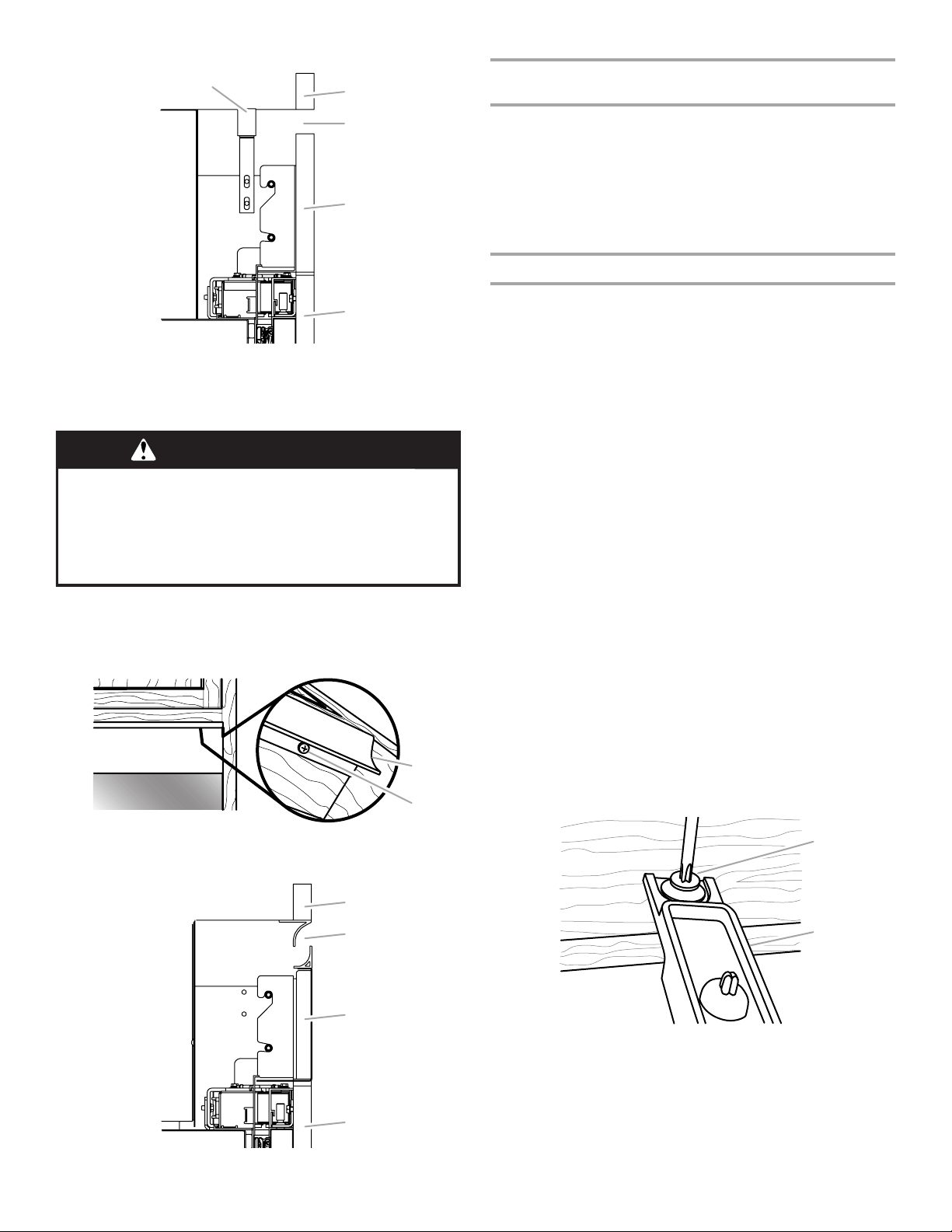
Vista lateral
B
C
D
A
B
A
B
C
D
A
B
A
Plantillas para el taladrado (solamente para los paneles
de madera a la medida)
IMPORTANTE: La plantilla puede usarse ya sea para una
instalación con mocheta de ³⁄₈" (0,95 cm) o de ¹⁄₈" (0,32 cm).
■ Las plantillas de taladrado tienen dos lados.
■ Ubique el diagrama de su refrigerador en la plantilla. Después
siga las letras y las flechas de colores para colocar
correctamente la plantilla de taladrado sobre los paneles.
■ Los orificios para taladrar se han cortado previamente en la
plantilla.
Preparación de los paneles recubiertos a la medida
E
A. Cubierta de la rejilla superior
B. Sofito
C. Flujo de aire
D. Panel de la rejilla
E. Panel de la puerta
Modelos con juego de paneles
ADVERTENCIA
Peligro de Peso Excesivo
Use dos o más personas para mover e instalar
los paneles.
No seguir esta instrucción puede ocasionar una lesión
en la espalda u otro tipo de lesiones.
1. Alinee la cubierta de la rejilla superior (provista con el juego de
puerta) con el borde inferior del sofito. Úsela como plantilla y
marque los lugares en donde se van a taladrar los orificios.
2. Usando los tornillos de cabeza ranurada hexagonal
(provistos), fije la cubierta de la rejilla superior al sofito.
A. Cubierta de la rejilla superior
B. Tornillo de cabeza hexagonal (provisto)
Vista lateral
IMPORTANTE:
■ El procedimiento para instalar los paneles recubiertos sobre el
refrigerador es el mismo para los paneles a la medida y para
los juegos de paneles.
■ Las plantillas de taladrado se usan solamente para los
paneles recubiertos de madera a la medida.
■ Los paneles que se incluyen en los juegos de paneles han
sido previamente taladrados solamente para los soportes de
montaje. Vea “Complete la instalación” más adelante en esta
sección para obtener instrucciones acerca de cómo taladrar
orificios adicionales en los paneles de la puerta.
NOTA: Para los paneles de las puertas del modelo de 36",
que se abren específicamente hacia la derecha y hacia la
izquierda, siga las instrucciones a continuación:
■ Manija del lado derecho - Use los orificios, ubicados en el
lado posterior del panel de la puerta, que están marcados
con un círculo rojo.
■ Manija del lado izquierdo - Use los orificios, ubicados en
el lado posterior del panel de la puerta, que están
marcados con un círculo azul.
■ La película protectora que cubre los paneles de acero
inoxidable de la puerta deberá quitarse antes de instalar los
soportes.
1. Coloque los paneles sobre una superficie firme y plana, con la
parte frontal mirando hacia abajo.
2. Usando las plantillas (provistas), taladre previamente orificios
piloto de ¹⁄₈" de profundidad en los rieles de madera que
bordean la(s) puerta(s), el cajón y los paneles de la rejilla
superior. Siga las instrucciones impresas en la plantilla.
3. Usando el bloque de instalación como guía para la
profundidad, atornille los pernos prisioneros (provistos) en el
panel de la puerta previamente taladrado (dos pernos
prisioneros por puerta).
38
A. Sofito
B. Flujo de aire
C. Panel de la rejilla
D. Panel de la puerta
A. Perno prisionero para puerta
B. Bloque de instalación
4. Inserte los tornillos puntiagudos de cabeza hexagonal
(provistos) en la madera que se encuentra en la parte superior
de los paneles de la puerta donde se taladraron previamente.
NOTA: Es fundamental usar el tornillo de ⁵⁄₈", el más largo que
se haya provisto, para fijar el soporte a la parte superior del
panel de la puerta. Estos tornillos puntiagudos de cabeza
hexagonal se usan solamente para fijar este soporte de
montaje.

5. Fije un soporte de montaje al extremo superior del (de los)
B
A
B
panel(es) de la puerta, colocando el extremo grande de la
bocallave sobre los tornillos, y deslizando el soporte para que
los tornillos queden centrados en las ranuras.
NOTA: Comience con los tornillos que están en el centro de
las ranuras, como se muestra; luego mueva el panel de la
puerta cuando sea necesario para alinearlo.
AB
A. Panel de la puerta B. Soporte de montaje
6. Usando los tornillos Phillips de cabeza plana (provistos),
sujete un soporte de montaje a cada lado del panel del cajón,
como se muestra.
A
B
2. Abra las puertas del refrigerador y del congelador.
3. Saque las piezas de la cubierta de la bisagra de la parte
superior e inferior de la puerta, para descubrir los orificios en
las bisagras.
NOTAS:
■ No es necesario quitar las cubiertas del lado de la bisagra,
ya que no van a interferir con la instalación.
■ Deje las cubiertas del cajón del congelador en su lugar
para la instalación.
A
C
A
A. Panel del cajón
B. Soporte de montaje del panel del cajón
7. Usando los tornillos de cabeza ranurada hexagonal provistos,
fije un soporte de montaje a cada lado del panel de la rejilla.
NOTAS:
■ Vea la hoja separada de Piezas provistas para seleccionar
los soportes designados para su instalación.
■ Use los soportes de la Rejilla incorporada para una
Instalación incorporada con una rejilla de altura completa.
■ Use los soportes estándar de la rejilla para una instalación
estándar con una rejilla alineada, como se muestra.
8. Usando los tornillos de cabeza redonda (provistos), sujete la
pieza de cubierta de la rejilla a la parte inferior del panel de la
misma.
A. Piezas de la cubierta de la bisagra
B. Cubierta de la puerta del lado de la manija
C. Cubierta del cajón
Cómo instalar los paneles de la puerta
1. Baje el soporte de montaje del panel sobre los pasadores de
ajuste en la parte superior de la puerta.
C
A. Panel de la puerta
B. Soporte de montaje
C.Pasadores de ajuste
2. Deslice los pernos prisioneros, ubicados en el lado posterior
del panel de la puerta, dentro de las cavidades en “J” que
están al frente de la puerta.
NOTA: Para los modelos de dos puertas con congelador en la
parte inferior, repita los pasos 1 y 2 para instalar el panel de la
segunda puerta.
A
B
A. Soportes de la rejilla superior
B. Pieza de cubierta de la rejilla
Saque las piezas de la cubierta
1. Quite toda la cinta y los refuerzos de las puertas del
refrigerador y del congelador.
39

3. Usando un tornillo de cabeza ranurada hexagonal (provisto),
C
fije el soporte de montaje (instalado de fábrica), ubicado en la
parte inferior de la(s) puerta(s) del refrigerador, a su(s)
panel(es) de puerta respectivo(s). No apriete el tornillo por
completo.
A B
A. Bisagra inferior
B. Soporte de montaje
Instalación del panel del cajón
1. Alinee las ranuras que están en los soportes de montaje,
ubicadas a cada lado del panel del cajón, con los orificios en
el cajón que atraviesan la cubierta del mismo.
2. Usando los tornillos Phillips de cabeza plana (provistos), fije
los soportes al cajón.
3. Mueva el panel del cajón hacia arriba y hacia abajo o de lado
a lado para alinearlo. No apriete los tornillos por completo.
B BA
A. Panel de la rejilla superior
B. Lados del armario
Cómo ajustar la oscilación de las puertas
Tal vez sea necesario ajustar la abertura de la(s) puerta(s).
Verifique que la(s) puerta(s) del refrigerador se pueda(n) abrir con
toda libertad. Si la(s) puerta(s) se abre(n) demasiado, instale el
pasador para el tope de la puerta (provisto).
1. Detenga la puerta abierta en un ángulo menor de 90°.
2. Inserte el pasador para el tope de la puerta en la bisagra
superior, en el orificio que se muestra.
3. Usando una llave Allen de ⁵⁄₃₂", apriete el pasador del tope de
la puerta.
A
A
B
A. Panel de revestimiento del cajón
B. Soporte de montaje del panel
Instalación del panel para la rejilla superior
Instalación estándar - Rejilla alineada
1. Enganche los soportes del panel sobre los pernos de montaje
que se extienden desde la parte superior del refrigerador.
2. Jale el panel de la rejilla levemente hacia abajo para
asegurarlo en su lugar.
Instalación incorporada - Rejilla de altura completa
1. Alinee el soporte con los pernos de montaje.
2. Empuje hacia delante el panel de la rejilla hasta que el soporte
encaje a presión en su lugar.
A. Orificio del pasador del tope de la puerta
Complete la instalación
1. Use el bloque de instalación para medir los espacios entre los
paneles recubiertos y los armarios adyacentes.
■ Los paneles de acero inoxidable requieren un espacio de
³⁄₈" (0,95 cm) entre el panel de acero inoxidable y los
armarios, y un espacio de ¹⁄₈" (0,32 cm) entre la puerta del
congelador y la del refrigerador, y las puertas y la rejilla
superior.
A
B
40
A. Armario adyacente
B. Bloque de instalación
C. Panel recubierto sobre la puerta

2. Ajuste el panel para lograr el espacio requerido o para
A
B
A
B
alinearlo.
IMPORTANTE: Si se necesita algún ajuste, ajuste el panel y
no la puerta.
■ Deslice el panel recubierto de un lado a otro en la
bocallave.
■ Use una llave Allen para levantar o bajar los pasadores de
ajuste, lo que permite que gire el panel de la puerta.
C
A. Panel de la puerta
B. Soporte de montaje
C. Pasadores de ajuste
3. Taladre previamente orificios piloto de ¹⁄₈" en el (los) panel(es)
de la puerta a través de los orificios abiertos en las bisagras
inferior y superior.
4. Usando los tornillos de cabeza ranurada hexagonal
(provistos), fije las bisagras superior e inferior a los paneles de
la puerta. Apriete por completo todos los tornillos del panel de
la puerta.
NOTA: Para los modelos de 36", hay un soporte adicional en
la parte superior para ajustar el panel recubierto a la puerta.
Inserte los tornillos a través del soporte y dentro del panel de
la puerta.
BA
DC E
A. Bisagra superior
B. Soporte de montaje regulable
C. Orificios para tornillos
D. Pasadores de ajuste de la puerta
E. Solamente para los modelos de
36" - Orificios para tornillos
5. Si es necesario, ajuste el panel del cajón para alinear y apretar
por completo todos los tornillos del panel del cajón.
6. Usando los tornillos de cabeza ranurada hexagonal (provistos)
para cada lado, fije los paneles de la puerta a las cubiertas de
la puerta del lado de la bisagra.
7. Usando los tornillos Phillips de cabeza plana (provistos),
instale la cubierta de la puerta del lado de la manija.
8. Apriete los tornillos por completo fijando los soportes de
montaje, ubicados en la base de las puertas, a los paneles
recubiertos.
9. Vuelva a instalar la cubierta de la puerta superior y la cubierta
de la bisagra.
10. Encaje a presión la cubierta del pasador de ajuste (provista)
en su lugar.
Instalación de las manijas
(Sólo para modelos con juego de paneles)
IMPORTANTE: Instale las manijas después de haber instalado los
paneles de la puerta.
Herramientas necesarias: Llave Allen de ³⁄₃₂"
1. Ubique los orificios en los paneles de la puerta en donde se
instalarán los pernos de montaje de las manijas.
2. Sujete los pernos de montaje de las manijas a los paneles de
la puerta.
3. Instale las manijas en los pernos de montaje y apriete los
tornillos opresores.
NOTA: Según la manija, los pernos opresores pueden ser una
pieza separada o un componente del perno de montaje.
Instalación de la rejilla de la base
La rejilla de base está formada por dos piezas para permitir un
encaje a la medida: la rejilla de la base misma y el faldón. Se
puede agregar el faldón a la rejilla de la base para extenderla
hasta el piso.
1. Para ver si se necesita el faldón, coloque la rejilla de la base
en su posición. No fije la rejilla de la base al refrigerador. Mida
la distancia entre la parte inferior de la rejilla de la base y el
piso. El espacio debe ser de ½" (1,27 cm) como mínimo para
agregar el faldón.
NOTA: Si el espacio mide menos de ½" (1,27 cm), saltee los
pasos 3 y 4 de las instrucciones e instale solamente la rejilla
de la base.
2. Saque la película protectora de la rejilla de la base.
3. Encaje a presión el faldón sobre la rejilla de la base.
A
B
A. Panel recubierto del cajón
B. Soporte de montaje del panel
A. Rejilla de la base
B. Faldón
41

4. Recorte el faldón trazando la muesca en forma de “V”
apropiada con un cuchillo para uso general. Parta el faldón en
la línea trazada.
A
A. Muesca en “V”
5. Usando los dos tornillos, fije el ensamblaje de la rejilla de la
base al refrigerador, como se muestra.
NOTA: Atornille primero el tornillo del lado derecho.
A
A. Tornillos (2)
Preparación del sistema de agua
Sírvase leer antes de usar el sistema de agua.
Inmediatamente después de la instalación, siga los pasos a
continuación para asegurarse de que el sistema de agua esté
debidamente limpio.
1. Abra la puerta del congelador y apague la fábrica de hielo.
Para el Estilo 1, levante el brazo de control de alambre como
se muestra. Para el Estilo 2, mueva el interruptor a la posición
OFF (Apagado - hacia la derecha) como se muestra. El
interruptor de On/Off (Encendido/Apagado) se encuentra en el
lado derecho superior del compartimiento del congelador.
Estilo 1 – Modelos sin despachador
Estilo 2 – Modelos con despachador
Cómo terminar la instalación
1. Gire la válvula de la tubería de alimentación de agua a la
posición “Abierta”.
2. Gire el interruptor del refrigerador a la posición ON
(Encendido). Vea la sección “Interruptor de Encendido/
Apagado” en el Manual de uso y cuidado, para las
instrucciones. Espere unos minutos. Busque fugas en las
conexiones de la tubería de agua.
3. Quite todas las cajas, paquetes de partes y materiales de
empaque del interior del refrigerador. Vea la sección
“Limpieza” en el Manual de uso y cuidado, para las
instrucciones. Quite la película y el cartón protector de la rejilla
y de las puertas o marco de la puerta, según su modelo.
4. Instale los estantes y recipientes en el refrigerador y en los
compartimientos del congelador.
5. Los controles están prefijados de fábrica en su posición
intermedia. Verifique que el compresor esté funcionando
correctamente y que todas las luces funcionan.
6. Enjuague el sistema de agua antes de utilizarlo. Vea
“Preparación del sistema de agua”.
Para obtener el uso más eficiente de su nuevo refrigerador
empotrado, lea el Manual de uso y cuidado. Conserve a mano las
Instrucciones de instalación y el Manual de uso y cuidado del
refrigerador empotrado para una consulta fácil.
NOTA: Si su modelo tiene un sistema de filtro de la rejilla de la
base, asegúrese de que el filtro de la rejilla de la base esté
instalado adecuadamente y que la tapa esté en la posición
horizontal.
No use con agua que no sea microbiológicamente segura
o que sea de calidad desconocida sin desinfectarla
adecuadamente antes o después del sistema. Pueden
usarse sistemas certificados para la reducción de quistes
en aguas desinfectadas que puedan contener quistes
filtrables.
2. Use un recipiente resistente para oprimir y sostener la barra
del despachador por 5 segundos, luego suéltela por
5 segundos. Repita hasta que el agua comience a correr. Una
vez que el agua comenzó a correr, continúe presionando y
soltando la barra del despachador (5 segundos activado,
5 segundos desactivado) por otros 2 minutos. Este proceso
eliminará el aire en el filtro y en el sistema de despacho de
agua. En algunas casas se podrá requerir enjuague adicional.
NOTA: A medida que sale aire del sistema, es posible que
salgan chorros de agua repentinos del despachador.
3. Abra la puerta del congelador y ponga la fábrica de hielo a
funcionar. Para el Estilo 1, baje el brazo de control de
alambre. Para el Estilo 2, mueva el interruptor a la posición de
ON (Encendido - hacia la izquierda).
■ Deje transcurrir 24 horas para la producción de la primera
tanda de hielo.
■ Deshágase de las tres primeras tandas de hielo
producido.
■ Dependiendo de su modelo, puede ser que Ud. desee
elegir la característica máxima de hielo para incrementar
la producción de hielo.
42

SÉCURITÉ DU RÉFRIGÉRATEUR
Votre sécurité et celle des autres est très importante.
Nous donnons de nombreux messages de sécurité importants dans ce manuel et sur votre appareil ménager. Assurez-vous de
toujours lire tous les messages de sécurité et de vous y conformer.
Voici le symbole d’alerte de sécurité.
Ce symbole d’alerte de sécurité vous signale les dangers potentiels de décès et de blessures graves à vous
et à d’autres.
Tous les messages de sécurité suivront le symbole d’alerte de sécurité et le mot “DANGER” ou
“AVERTISSEMENT”. Ces mots signifient :
Risque possible de décès ou de blessure grave si vous ne
DANGER
AVERTISSEMENT
Tous les messages de sécurité vous diront quel est le danger potentiel et vous disent comment réduire le risque de blessure et
ce qui peut se produire en cas de non-respect des instructions.
AVERTISSEMENT
suivez pas immédiatement les instructions.
Risque possible de décès ou de blessure grave si vous
ne suivez pas les instructions.
Risque de basculement
Le réfrigérateur est lourd au sommet et bascule
facilement lorsqu'il n'est pas complètement installé.
Garder les portes fermées avec un ruban adhésif
jusqu'à l'installation complète du réfrigérateur.
Utiliser deux ou plus de personnes pour déplacer et
installer le réfrigérateur.
Le non-respect de ces instructions peut causer un
décès ou une blessure grave.
43

MODÈLES DE 36"
Conception intégrée
Comporte du matériel et des panneaux personnalisés fournis
par l’ébéniste pour une apparence harmonieuse conçue pour
s’intégrer aux meubles de cuisine existants.
Numéros de modèles de base : JB36NXFXLW, JB36NXFXRW
Conception en acier inoxydable Pro-Style
Portes habillage en acier inoxydable et poignées Pro-Style® avec
surface de saisie à texture gravée (losanges).
Numéros de modèles de base : JB36NXFXLW, JB36NXFXRW
Numéro de modèle d’ensemble : JPK36BNXWPS
®
Ensembles de poignées de porte
Euro-Style et Pro-Style
Toutes les pièces d’usine sont disponibles chez votre marchand
Jenn-Air ou en appelant Jenn-Air au 1-800-JENNAIR
(1-800-536-6247). Au Canada, composer le 1-800-807-6777.
Suivre les instructions de l'ensemble pour l’installation des poignées
de porte.
Acier inoxydable Pro-Style
Réfrigérateur avec congélateur en bas W10250641
Acier inoxydable Euro-Style - Réfrigérateur avec congélateur en
bas W10250635
®
-
®
Conception en acier inoxydable Euro-Style
Portes avec habillage en acier inoxydable et nouvelles poignées
Euro-Style assorties aux produits Euro kitchen suite de Jenn-Air et
qui rehaussent tout décor de cuisine.
Numéros de modèles de base : JB36NXFXLW, JB36NXFXRW
Numéro de modèle d’ensemble : JPK36BNXWES
44

MODÈLES DE PORTE À DOUBLE BATTANT DE 42"
Conception intégrée
Comporte du matériel et des panneaux personnalisés fournis par
l’ébéniste pour une apparence harmonieuse conçue pour s’intégrer
aux meubles de cuisine existants.
Numéro de modèle de base : JF42NXFXDW
Conception en acier inoxydable Pro-Style
Portes habillage en acier inoxydable et poignées Pro-Style® avec
surface de saisie à texture gravée (losanges).
Numéro de modèle de base : JF42NXFXDW
Numéro de modèle d’ensemble : JPK42FNXWPS
®
Ensembles de poignées de porte
Euro-Style et Pro-Style
Toutes les pièces d’usine sont disponibles chez votre marchand
Jenn-Air ou en appelant Jenn-Air au 1-800-JENNAIR
(1-800-536-6247). Au Canada, composer le 1-800-807-6777.
Suivre les instructions de l'ensemble pour l’installation des poignées
de porte.
Acier inoxydable Pro-Style
Porte du congélateur monté en bas W10250642
Acier inoxydable Euro-Style Porte du congélateur monté en bas W10250636
®
-
®
Conception en acier inoxydable Euro-Style
Portes avec habillage en acier inoxydable et nouvelles poignées
Euro-Style assorties aux produits Euro kitchen suite de Jenn-Air et
qui rehaussent tout décor de cuisine.
Numéro de modèle de base : JF42NXFXDW
Numéro de modèle d’ensemble : JPK42FNXWES
45

EXIGENCES D’INSTALLATION
Outillage et pièces
IMPORTANT :
■ Installateur : Remettre les instructions d'installation au
propriétaire.
■ Propriétaire : Conserver les instructions d'installation pour
référence ultérieure. Conserver ces instructions d'installation
pour consultation par l'inspecteur local des installations
électriques.
OUTILLAGE REQUIS :
Rassembler les outils et pièces nécessaires avant de commencer
l'installation. Lire et suivre les instructions fournies avec les outils
indiqués ici :
■ Perceuse sans fil
■ Forets
■ Deux clés à molette
■ Tournevis Phillips
■ Petit niveau
■ Chariot pour appareil
ménager
■ Clé Allen de ³⁄₃₂" (ensembles
de panneaux uniquement)
PIÈCES NÉCESSAIRES :
■ Six vis à bois n° 8 x 3" (7,6 cm) (il peut être nécessaire
d'utiliser des vis plus longues)
■ Une ou deux planche(s) de bois de 2" x 4" x 32" (5 cm x
10 cm x 81 cm)
■ Conception intégrée - consulter un ébéniste ou un menuisier
qualifié pour la réalisation des panneaux de bois
personnalisés. Voir “Panneaux décoratifs personnalisés de
série intégrée” pour plus d'informations.
Conception en acier inoxydable - l'ensemble de panneaux est
livré avec le réfrigérateur.
■ Tuyau d’alimentation en eau flexible approuvé par les codes
en vigueur, une virole, un raccord et un raccord de
compression de ¹⁄₄" (6.35 mm) .
■ Tourne-écrou de ¹¹⁄₃₂"
■ Clés plates de ³⁄₈" et ½"
■ Clé Allen de ⁵⁄₃₂" et ³⁄₁₆"
■ Clé à douille, avec douilles
de ¹⁄₄" et ⁵⁄₁₆"
■ Mètre-ruban
■ Couteau utilitaire
■ Ruban de masquage
(pour peinture)
Exigences d'emplacement
AVERTISSEMENT
Risque d'explosion
Garder les matériaux et les vapeurs inflammables, telle
que l'essence, loin du réfrigérateur.
Le non-respect de cette instruction peut causer
un décès, une explosion ou un incendie.
IMPORTANT :
■ Respecter les dispositions de tous les codes et règlements en
vigueur.
■ Il est conseillé de ne pas installer le réfrigérateur près d'un
four, d'un radiateur ou de toute autre source de chaleur.
■ Ne pas installer l'appareil en un endroit où la température
pourrait descendre en-dessous de 55°F (13°C).
■ Le plancher doit pouvoir supporter le poids du réfrigérateur,
soit plus de 272 kg (600 lb), en plus des panneaux de porte et
du contenu du réfrigérateur.
■ La hauteur libre sous plafond doit être suffisante pour
permettre le basculement de chaque côté. Voir “Rayon de
basculement” plus loin dans cette section.
■ L’emplacement doit permettre l’ouverture complète de la
porte. Voir “Dimensions pour le pivotement des portes”.
■ L'emplacement d'installation doit permettre la dépose de la
grille supérieure. Voir “Dimensions d’ouverture
d’encastrement”.
Dimensions de l’ouverture d’encastrement
46
■ Un soffite ou placard robuste doit être installé à 84" (213,4 cm)
au-dessus du plancher. Si le soffite en matériau robuste est
d’une hauteur supérieure à 84" (213,4 cm) ou s’il n’y en a pas,
le réfrigérateur doit être arrimé.
Si les planches anti-basculement sont nécessaires, elles
doivent être fixées aux goujons du mur arrière de façon à ce
qu’il y ait 84" (213,4 cm) entre le bas de la planche antibasculement et le plancher. Voir “Installation des planches
anti-basculement” pour plus d’informations.
■ Pour une installation intégrée, une ouverture d’encastrement
de 6" (15,24 cm) au minimum au dessus du réfrigérateur est
nécessaire. Voir la section “Installation intégrée”. Des
planches anti-basculement sont requises. Voir “Installation
des planches anti-basculement” pour plus d’informations.
■ La largeur de l’ouverture d’encastrement d’un côté à l’autre
doit être telle que spécifiée par le modèle concerné, pour au
moins 2" (5,08 cm) en retrait de l’avant du meuble. Si
l’ouverture d’encastrement ne respecte pas cette condition,
des modifications devront être apportées.
■ Une prise électrique à trois broches avec mise à la terre doit
être placée à moins de 4" (10,2 cm) des meubles de droite ou
du panneau d’extrémité de droite. Voir la section “Exigences
électriques” pour plus d’informations.

■ Le robinet d’arrêt d’eau doit être situé dans le meuble inférieur
d’un côté ou de l'autre du réfrigérateur, ou à un autre endroit
facilement accessible. Si le robinet d’arrêt ne se trouve pas
dans les meubles, la plomberie d’arrivée d’eau peut provenir
du plancher. Voir la section “Exigences de l’alimentation en
eau” pour plus d’informations.
Spécifications électriques
AVERTISSEMENT
80" - 90"
(203-229 cm)
84" (213,4 cm)
jusqu’au bas du soffite plein
A
Largeur
(voir le tableau suivant)
B
1"
6"
(15,2 cm)
(2,54 cm)
Modèle Largeur A (telle
qu’indiquée ci-dessus)
4"
(10,2 cm)
77"
(196 cm)
(15,2 cm)
Risque de choc électrique
Brancher sur une prise à 3 alvéoles reliée à la terre.
Ne pas enlever la broche de liaison à la terre.
Ne pas utiliser un adaptateur.
Ne pas utiliser un câble de rallonge.
Le non-respect de ces instructions peut causer
un décès, un incendie ou un choc électrique.
Avant de placer le réfrigérateur à son emplacement final, il est
important de vous assurer d'avoir la connexion électrique
appropriée.
Méthode recommandée de mise à la terre
Une source d'alimentation de 115 volts, 60 Hz, type 15 ou 20 amp
CA seulement, protégée par fusible et adéquatement mise à la
terre est nécessaire. Il est recommandé d'utiliser un circuit distinct
pour alimenter uniquement votre réfrigérateur. Utiliser une prise
murale qui ne peut être mise hors circuit à l'aide d'un
commutateur. Ne pas utiliser de cordon de rallonge.
IMPORTANT : Si ce produit est connecté à une prise protégée
par un disjoncteur de fuite à la terre, un déclenchement
intempestif peut se produire et causer une perte de
refroidissement. La qualité et la saveur des aliments risquent
d'être affectées. Si un déclenchement intempestif se produit et si
les aliments semblent de piètre qualité, jeter le tout.
REMARQUE : Avant d'exécuter tout type d'installation, nettoyage
ou remplacement d'une ampoule d'éclairage, enlever la grille
supérieure et mettre l'interrupteur général d'alimentation à OFF
(arrêt) ou déconnecter la source de courant électrique au boîtier
de disjoncteurs.
6"
Lorsque vous avez terminé, mettre l'interrupteur général
d'alimentation à ON (marche) ou reconnecter la source de courant
électrique au boîtier de disjoncteurs. Puis remettre la commande
au réglage désiré.
36
42
36" (91,4 cm)
42" (106,7 cm)
Type d’installation Profondeur B (telle
qu’illustrée ci-dessus)
Standard - Affleurement
25" (63,5 cm) minimum
(nouvelle installation)
Modernisations 24" (60,9 cm) minimum
IMPORTANT :
■ Le revêtement de sol sous le réfrigérateur doit se trouver
au même niveau que le sol de la pièce. L’avant des
placards doit être d’aplomb.
■ La largeur de l’ouverture d’encastrement (largeur A) doit
être telle que spécifiée pour le modèle concerné, pour au
moins 2" (5,08 cm) en retrait de l’avant du meuble. Si
l’ouverture d’encastrement ne respecte pas cette
condition, des modifications devront être apportées.
47

Spécifications de l’alimentation en eau
■ Toutes les installations doivent être conformes aux exigences
des codes locaux de plomberie.
■ La canalisation d’alimentation en eau doit traverser le
plancher à l’endroit de la zone grisée, tel qu’illustré.
■ Le robinet d'arrêt doit se trouver dans le placard inférieur, d'un
côté ou de l'autre du réfrigérateur ou à un autre endroit
facilement accessible. Le côté droit est recommandé.
REMARQUE : Si un robinet d’arrêt se trouve dans un mur
situé derrière le réfrigérateur, il n’y a pas suffisamment
d’espace pour une installation en affleurement.
6"
(15,2 cm)
■ Laisser le réservoir du système d'osmose inverse se remplir
après une utilisation intense.
■ Si votre réfrigérateur a une cartouche de filtre à eau, celle-ci
peut réduire encore plus la pression de l'eau lorsqu'elle est
utilisée avec un système d'osmose inverse. Retirer la
cartouche du filtre à eau.
Si vous avez des questions au sujet de la pression de votre eau,
appeler un plombier qualifié agréé.
Dimensions du produit
IMPORTANT :
■ La profondeur entre l'avant des portes et l’arrière de la caisse
du réfrigérateur est de 24" (60,96 cm) sans les panneaux.
■ Le cordon d'alimentation mesure 84'' (213 cm) de long.
■ La canalisation d’alimentation en eau se trouve à l’avant du
réfrigérateur.
Réfrigérateur de 36" avec congélateur en bas
Vue de dessus
6"
(15,2 cm)
■ Un trou de ½" (12,7 mm) pour la plomberie doit être percé à 6"
1"
(2,54 cm)
6"
(15,2 cm)
(15,2 cm) minimum du placard de gauche ou de droite ou du
panneau. Sur le plancher, le trou ne doit pas se trouver à plus
de 1" (2,54 cm) du mur arrière. Voir “Raccordement de la
canalisation d'eau”.
■ Si un tube supplémentaire est nécessaire, utiliser un tube en
cuivre et vérifier s’il y a des fuites. Installer les tuyaux en cuivre
seulement là où les températures du domicile resteront audessus du point de congélation.
■ Ne pas employer de robinet d’arrêt à étrier de ³⁄₁₆" (4,76 mm)
ou de type à percer, ce qui réduit le débit d’eau et cause une
obstruction plus facilement.
REMARQUE : Votre marchand de réfrigérateurs offre une
trousse avec un robinet d’arrêt à étrier de ¹⁄₄" (6,35 mm), un
raccord et un tube en cuivre. Avant l’achat, s’assurer que le
robinet d’arrêt à étrier est conforme aux codes locaux de
plomberie.
Pression de l'eau
Une alimentation en eau froide avec une pression entre 30 et
120 lb/po
le distributeur d'eau et la machine à glaçons. Si vous avez des
questions au sujet de la pression de votre eau, appeler un
plombier qualifié agréé.
2
(207 et 827 kPa) est nécessaire pour faire fonctionner
Alimentation en eau par osmose inverse
IMPORTANT : La pression de l'alimentation en eau entre le
système d'osmose inverse et la valve d'arrivée d'eau du
réfrigérateur doit être entre 30 et 120 lb/po² (207 à 827 kPa).
Si un système de purification de l'eau par osmose inverse est
raccordé à votre alimentation en eau froide, la pression de l'eau
au système doit être d'un minimum de 40 à 60 lb/po² (276 à
414 kPa).
Si la pression de l'eau au système d'osmose inverse est inférieure
à 40 à 60 lb/po
■ Vérifier pour voir si le filtre du système d'osmose inverse est
bloqué et le remplacer si nécessaire.
2
(276 à 414 kPa) :
24"
(61,0 cm)
35³⁄₄"
(90,8 cm)
Vue de face
■ Les dimensions de largeur ont été relevées du rebord d’une
charnière au rebord de l’attache.
35³⁄₄"
(90,8 cm)
84"
(213,4 cm)
48

Réfrigérateur de 42"
avec congélateur en bas et porte à double battant
Top Vi ew
24"
(61,0 cm)
41³⁄₄"
(106,1 cm)
Vue de face
■ Les dimensions de largeur ont été relevées du rebord d’une
charnière au rebord de l’autre.
41³⁄₄"
(106,1 cm)
Rayon de basculement latéral
(modèles de 36" [91,4 cm])
A
A. 88
⁷⁄₈
" (225,7 cm)
Rayon de basculement latéral
(modèles de 42" [106,7 cm])
84"
(213,4 cm)
Rayon de basculement
Avant d'apporter le réfrigérateur dans le domicile, s'assurer que la
hauteur du plafond est suffisante pour mettre le réfrigérateur en
position verticale.
■ Si le réfrigérateur est installé sur un chariot à roulettes, on doit
ajouter la hauteur du chariot au rayon de basculement.
■ Si nécessaire, le rayon de basculement peut être réduit. Voir
“Réduction du rayon de basculement”.
REMARQUE : Ne faire basculer que latéralement.
A
A. 91
³⁄₈
" (232,1 cm)
Dimensions pour l’ouverture des portes
L’emplacement d'installation doit permettre l’ouverture des deux
portes à un angle minimal de 90°. Laisser un espace libre d'au
moins 4¹⁄₂" (11,4 cm) entre le côté du réfrigérateur et un mur
d'angle.
REMARQUE : Un dégagement plus grand peut être nécessaire si
l’on utilise des panneaux décoratifs, des poignées personnalisées
ou des poignées de plus grande profondeur.
BA C D
90˚
110˚
90˚
110˚
Modèle A B C D
36 36"
(91,4 cm)
42 42"
(106,7 cm)
39³⁄₄"
(101,0 cm)
42"
(106,7 cm)
45³⁄₈"
(115,3 cm)
48⁵⁄₈
(123,5 cm)
46³⁄₄"
(118,8 cm)
50¹⁄₄
(127,6 cm)
49

Options d’installation du placard
et du panneau
Profondeur de placard - 25" (63,5 cm)
Meubles à encadrement
Vue du dessus - Apparent
Profondeur de placard - 24" (60,9 cm)
Meubles à encadrement
Vue du dessus
E
D
C
E
D
C
A. Porte du réfrigérateur
B. Panneau décoratif
C. Garniture latérale
A B
D. Placard adjacent
E. Support de grille
A B
A. Porte du réfrigérateur
B. Panneau décoratif
C. Garniture latérale
Vue du dessus - Intégré
A B
A. Porte du réfrigérateur
B. Panneau décoratif
C. Garniture latérale
Meubles sans encadrement
A B
A. Porte du réfrigérateur
B. Panneau décoratif
C. Garniture latérale
D. Placard adjacent
E. Support de grille
E
D
C
D. Placard adjacent
E. Support de grille
E
D
C
D. Placard adjacent
E. Support de grille
Meubles sans encadrement
Vue du dessus
E
D
C
A B
A. Porte du réfrigérateur
B. Panneau décoratif
C. Garniture latérale
D. Placard adjacent
E. Support de grille
Exigences d’une installation intégrée
Le réfrigérateur peut être intégralement encastré si les meubles
adjacents satisfont les conditions de circulation d'air essentielles
au bon fonctionnement du réfrigérateur.
IMPORTANT :
■ Les installations standard et intégrée peuvent être réalisées
avec un dégagement de 24" (60,9 cm) ou 25" (63,5 cm) de
profondeur.
■ Une grille de pleine hauteur est utilisée pour réaliser une
installation totalement intégrée. Utiliser le support intégré
(fourni) pour fixer la grille de pleine hauteur.
REMARQUE : Un panneau de remplissage de la grille
supérieure n’est pas nécessaire avec une grille de pleine
hauteur.
Support de grille intégrée
50

Installation intégrée - Vue latérale
A
B
C
D
Option 2 - Avant décoratif (façade de meuble uniquement)
6" (15,24 cm)
min.
A. Avant décoratif (facultatif)
B. Circulation d'air
C. Grille de pleine hauteur
D. Panneau de porte
Exigences de circulation d'air pour l'aération
Les installations intégrées exigent un dégagement de 6"
(15,24 cm) au moins au-dessus du réfrigérateur. Cet espace doit
être totalement dégagé, notamment d’éventuels soffites.
Option 1 - Ouverture vers le plafond
6" (15,24 cm)
min.
Panneaux décoratifs sur mesure
Les panneaux décoratifs sur mesure vous permettent
d’harmoniser l'extérieur de votre réfrigérateur avec l'ensemble du
décor de la cuisine et d'utiliser des poignées personnalisées pour
une plus grande souplesse de design.
Dans certains cas, le fabricant des placards peut préférer travailler
avec un seul panneau usiné pour différentes dimensions. Suivre
les instructions relatives aux dimensions et au placement du
panneau pour s’assurer que les panneaux décoratifs sur mesure
conviendront parfaitement.
IMPORTANT :
■ Pour les modèles de 36" (91,4 cm), le panneau décoratif de la
porte du réfrigérateur ne doit pas excéder 60 lb (27,2 kg) et le
panneau décoratif du tiroir du congélateur ne doit pas excéder
25 lb (11,3 kg).
■ Pour les modèles de 42" (106,7 cm), le panneau décoratif de
la porte du réfrigérateur ne doit pas excéder 40 lb (18,1 kg) et
le panneau décoratif du tiroir du congélateur ne doit pas
excéder 30 lb (13,6 kg).
■ Pour les deux modèles, le poids du panneau décoratif de la
grille supérieure ne doit pas excéder 7 lb (3,2 kg).
■ L’épaisseur nécessaire pour tous les panneaux est de ³⁄₄"
(1,91 cm).
■ Cette installation ne nécessite pas de panneaux de
remplissage ni de panneaux d’appui.
51

Dimensions des panneaux décoratifs
Modèle de 36" (91,4 cm) - Panneaux de porte et de tiroir 42" Modèle de 42" (106,7 cm)
Panneaux de porte et de tiroir
52³⁄₈"
(133,03 cm)
20¹⁄₂"
(52,07 cm)
A
PANNEAU DE PORTE DU
RÉFRIGÉRATEUR
Poids maximal : 60 lbs (27,2 kg)
B
PANNEAU TIROIR DU
CONGÉLATEUR
Poids maximal : 25 lb (11,34 kg)
52³⁄₈"
(133,03 cm)
20¹⁄₂"
(52,07 cm)
A
PANNEAU DE
PORTE DU
RÉFRIGÉRATEUR
Poids maximal :
40 lbs (18,14 kg)
PANNEAU TIROIR DU
CONGÉLATEUR
Poids maximal : 30 lb (13,6 kg)
RÉFRIGÉRATEUR
Poids maximal :
40 lbs (18,14 kg)
B
A
PANNEAU DE
PORTE DU
MISE EN GARDE
Risque de pincement
L'installation de panneaux de porte avec un espacement de
moins de ³⁄₈" (0,95 cm) entre le panneau de porte et le
placard adjacent augmente le risque de pincement potentiel.
Modèle 36" avec congélateur en bas
Retrait ³⁄₈" ¹⁄₈"
A 35¹⁄₄" (89,54 cm) 35³⁄₄" (90,81 cm)
B 35¹⁄₄" (89,54 cm) 35³⁄₄" (90,81 cm)
MISE EN GARDE
Risque de pincement
L'installation de panneaux de porte avec un espacement de
moins de ³⁄₈" (0,95 cm) entre le panneau de porte et le
placard adjacent augmente le risque de pincement potentiel.
Modèle 42" avec congélateur en bas et
porte à double battant
Retrait ³⁄₈" ¹⁄₈"
A 20 ⁹⁄₁₆" (52,23 cm) 20¹³⁄₁₆" (52,86 cm)
B 41¹⁄₄" (104,76 cm) 41³⁄₄" (106,05 cm)
Panneau de la grille
Installation intégrée - Grille de pleine hauteur
C
⁵⁄₈"
6
(16,83 cm)
Mo-
dèle
Retrait ³⁄₈" ¹⁄₈" ³⁄₈" ¹⁄₈"
C 35¹⁄₄"
(89,54 cm)
Panneau de la grille supérieure
36 42
35³⁄₄"
(90,81 cm)
41¹⁄₄"
(104,76 cm)
41³⁄₄"
(106,05 cm)
52

Installation standard - Grille affleurante
D
1" (2,54 cm)
5
(14,55 cm)
Planche de remplissage de la grille supérieure
E
³⁄₄"
Panneau de la grille supérieure
2. Si nécessaire, réduire le rayon de basculement. Au sujet des
critères à respecter pour la hauteur sous plafond, voir “Rayon
de basculement”.
Déplacement du réfrigérateur
dans le domicile
AVERTISSEMENT
Mo-
dèle
Retrait ³⁄₈" ¹⁄₈" ³⁄₈" ¹⁄₈"
D 35¹⁄₄"
(89,54 cm)
E 35¹⁄₄
(89,54 cm)
IMPORTANT : La hauteur du panneau de grille, illustré dans
l’image de la section Installation standard - Grille affleurante,
assure une circulation d’air essentielle au bon fonctionnement du
réfrigérateur.
36 42
35³⁄₄"
(90,81 cm)
35³⁄₄"
(90,81 cm)
41¹⁄₄"
(104,76 cm)
41¹⁄₄"
(104,76 cm)
41³⁄₄"
(106,05 cm)
41³⁄₄"
(106,05 cm)
INSTRUCTIONS
D’INSTALLATION
Déballage du réfrigérateur
AVERTISSEMENT
Risque de basculement
Le réfrigérateur est lourd au sommet et bascule
facilement lorsqu'il n'est pas complètement installé.
Garder les portes fermées avec un ruban adhésif
jusqu'à l'installation complète du réfrigérateur.
Utiliser deux ou plus de personnes pour déplacer et
installer le réfrigérateur.
Le non-respect de ces instructions peut causer un
décès ou une blessure grave.
1. Introduire un chariot de manipulation sous le côté gauche du
réfrigérateur, tel qu'illustré. À cette fin, placer les coins de
protection de l'emballage sur les garnitures comme il
convient. Serrer lentement la sangle.
Risque de basculement
Le réfrigérateur est lourd au sommet et bascule
facilement lorsqu'il n'est pas complètement installé.
Garder les portes fermées avec un ruban adhésif
jusqu'à l'installation complète du réfrigérateur.
Utiliser deux ou plus de personnes pour déplacer et
installer le réfrigérateur.
Le non-respect de ces instructions peut causer un
décès ou une blessure grave.
IMPORTANT :
■ Ne pas ôter la pellicule avant que le réfrigérateur ne soit à la
position de service.
■ Les quatre pieds de réglage de l'aplomb doivent toucher le
plancher pour supporter et stabiliser le poids total du
réfrigérateur.
■ Garder la pièce de carton ou de contreplaqué d’expédition
sous le réfrigérateur jusqu’à son installation à l’emplacement
de service.
1. Retirer et conserver le sachet de documents fixé à l’aide de
ruban adhésif sur le côté du réfrigérateur et le sachet de
pièces derrière la grille. Enlever les quatre brides (deux de
chaque côté) fixant la base utilisée pour l’expédition au bas du
réfrigérateur.
REMARQUE : Ne pas enlever les rubans adhésifs et articles
d'arrimage des portes avant que le réfrigérateur ne soit placé
à sa position finale.
2. Placer des bouts du carton d’expédition sur le plancher
lorsqu’on fait rouler le chariot et le réfrigérateur pour les faire
entrer dans le domicile. Approcher le réfrigérateur près de
l'ouverture d’encastrement.
3. Placer le dessus du carton ou du contreplaqué sous le
réfrigérateur.
4. Mettre le réfrigérateur en position verticale. Placer d'abord le
bord inférieur gauche du réfrigérateur sur le plancher, puis
mettre le réfrigérateur debout et abaisser ensuite le côté droit
du réfrigérateur sur le plancher.
53

Installation de planches antibasculement
E
A
B
C
IMPORTANT :
■ Si aucun soffite plein n’est disponible, une planche anti-
basculement doit être installée.
■ On recommande la mise en place d’une ou de plusieurs
planches avant l'installation du réfrigérateur.
■ Il faut que la ou les planches soit(soient) assez longue(s) pour
recouvrir complètement le couvercle du compresseur sur
toute la largeur.
■ Positionner la ou les planches de telle manière que la surface
inférieure soit à 84" (213 cm) du plancher.
■ Durant l'installation, soulever le réfrigérateur pour que la
distance résiduelle entre le sommet du réfrigérateur et la
surface inférieure de la ou des planche(s) antibasculement soit
de ¹⁄₄" (6,35 mm) maximum. Veiller à ne pas écraser le
couvercle du compresseur lors du soulèvement des pieds de
réglage de l'aplomb arrière.
Installation des planches antibasculement
1. Marquer la position des poteaux de colombage sur le mur
arrière de 80" à 90" (203 à 229 cm) au-dessus du plancher.
2. Fixer solidement une ou deux planches de 2" x 4" x 32"
(5 cm x 10 cm x 81 cm) sur les poteaux de colombage
derrière le réfrigérateur. Utiliser 6 vis à bois n
(ou plus longues). Les vis à bois doivent pénétrer dans les
poteaux d'au moins 1½" (3,8 cm). La ou les planche(s) doit
(doivent) être placée(s) en chevauchement sur le couvercle du
compresseur.
o
8 x 3" (7,6 cm)
Raccordement à l'alimentation en eau
Lire toutes les instructions avant de commencer.
IMPORTANT : Si l'on doit mettre en marche le réfrigérateur avant
que la canalisation d'eau ne soit connectée, placer la machine à
glaçons à OFF (arrêt).
Raccordement à la canalisation d'eau
Pièces nécessaires :
■ Canalisation flexible d'alimentation en eau approuvée par les
codes en vigueur de 7 pi (2,13 m)
Style 1 – Connexion avec robinet d'arrêt
REMARQUE : Si le raccordement de la canalisation d’eau ne
ressemble pas au Style 1, voir “Style 2 – Raccordement de la
canalisation en cuivre”.
1. Débrancher le réfrigérateur ou déconnecter la source de
courant électrique.
IMPORTANT : Avant de raccorder le tube au robinet d’arrêt, rincer
la canalisation d'eau principale pour éliminer l'air et les débris qui
s'y trouvent. Laisser s'écouler une quantité d'eau suffisante,
jusqu'à ce qu’elle soit limpide. Le rinçage de la canalisation d’eau
peut permettre d'éviter l’obstruction des filtres et/ou celle des
robinets.
2. Raccorder la canalisation flexible d'alimentation en eau
approuvée par les codes en vigueur au robinet d'arrêt en
enfilant l'écrou fourni sur le robinet d'arrêt, tel qu'illustré.
BA
C
¹⁄₄" (6 mm)
max.
2" (5 cm)
84"
(213,4 cm)
D
A. Centrer la planche à un maximum de ¹⁄₄" (6,35 mm) au-dessus du
réfrigérateur.
B. Deux planches de 2" x 4" x 32" (5 cm x 10 cm x 81 cm)
C. Fixer aux poteaux avec 6 vis n
D. Couvercle du compresseur
E. Distance entre le bas de la planche anti-basculement et le plancher
o
8 x 3" (7,6 cm)
A. Renflement
B. Écrou
C. Tuyau d'eau
3. Placer l'extrémité du tube dans un seau et OUVRIR le robinet
d'arrêt.
4. Vérifier qu'il n'y a pas de fuites. Si des fuites sont identifiées,
resserrer tous les écrous ou connexions concernés (y compris
les connexions au niveau du robinet).
Style 2 – Raccordement de la canalisation d’eau en cuivre
REMARQUE : S'il y a une canalisation d'alimentation en eau qui
satisfait aux exigences de “Exigences d'alimentation en eau”,
passer à “Raccordement au réfrigérateur”. Si ce n'est pas le cas,
utiliser les instructions suivantes pour le raccordement à
l'alimentation d'eau froide du domicile.
1. Débrancher le réfrigérateur ou déconnecter la source de
courant électrique.
2. FERMER le robinet principal d’alimentation en eau. OUVRIR le
robinet le plus proche pendant une période suffisante pour
purger toute l'eau de la canalisation.
54

3. Identifier une canalisation d'eau froide verticale de ½" à 1¹⁄₄"
A
B
C
D
E
F
G
(1,25 cm à 3,18 cm) à proximité du réfrigérateur.
IMPORTANT :
■ Vérifier qu'il s'agit d'une canalisation d'eau froide.
■ On peut aussi utiliser une canalisation horizontale; dans ce
cas, on devra percer sur la face supérieure du tuyau et
non pas au-dessous. Ceci permet de tenir la perceuse à
l'écart de l'eau et d'empêcher les sédiments qu'on trouve
normalement dans l'eau de s'accumuler dans le robinet
d'arrêt.
4. Déterminer la longueur de tube de cuivre à utiliser. Mesurer
depuis le point de connexion (angle inférieur arrière gauche du
réfrigérateur) et la canalisation d'eau. Ajouter 7 pi (2,1 m) pour
permettre les opérations de nettoyage. Utiliser un tube en
cuivre de ¹⁄₄" (6,35 mm) de diamètre extérieur. Veiller à ce que
le tube soit coupé d’équerre aux deux extrémités.
5. À l'aide d'une perceuse sans fil, percer un trou de ¹⁄₄"
(6,35 mm) dans la canalisation d'eau froide choisie.
A
G
B
C
DEF
A. Canalisation d'eau froide
B. Bride de tuyau
C. Tube en cuivre
D. Écrou de compression
E. Bague de compression
F. Robinet d'arrêt
G. Écrou de serrage
6. Fixer le robinet d’arrêt sur la canalisation d'eau froide avec la
bride de tuyau. Vérifier que l'extrémité du raccord du robinet
est bien engagée dans le trou de ¹⁄₄" (6,35 mm) percé dans la
canalisation et que la rondelle d'étanchéité se trouve sous la
bride du tuyau. Serrer l'écrou de serrage. Serrer lentement et
uniformément les vis fixant la bride de tuyau sur le tuyau afin
d'assurer l'étanchéité du joint. Ne pas serrer excessivement.
IMPORTANT : Avant de raccorder le tube au robinet d’arrêt, rincer
la canalisation d'eau principale pour éliminer l'air et les débris qui
s'y trouvent. Laisser s'écouler une quantité d'eau suffisante,
jusqu'à ce qu’elle soit limpide. Le rinçage de la canalisation d’eau
peut permettre d'éviter l’obstruction des filtres et/ou celle des
robinets.
7. Enfiler la bague et l'écrou de compression sur le tube en
cuivre tel qu'illustré. Insérer l'extrémité du tube directement
dans l'extrémité de sortie, aussi loin que possible. Visser
l'écrou de compression sur l'extrémité de sortie du raccord à
l'aide d'une clé à molette. Ne pas serrer excessivement la
bride ou la bague. Ceci provoquera l’écrasement du tube de
cuivre.
8. Fermer le robinet d'arrêt de la canalisation d'eau. Lover le
tube de cuivre.
9. Raccorder la canalisation flexible d'alimentation en eau
approuvée par les codes en vigueur au robinet d'arrêt en
enfilant l'écrou fourni sur le robinet d'arrêt.
10. Placer l'extrémité du tube dans un seau et OUVRIR le robinet
d'arrêt.
11. Inspecter pour rechercher des fuites au niveau du robinet
d'arrêt à étrier. Si des fuites sont identifiées, resserrer tous les
écrous ou connexions concernés (y compris les connexions
au niveau du robinet).
1"
7"
(17,78 cm)
(2,54 cm)
REMARQUE : La canalisation flexible d'alimentation en eau
approuvée par les codes en vigueur peut être raccordée au
robinet d'alimentation en eau par le plancher ou par les placards
latéraux, tel qu'indiqué dans les encadrés gris ci-dessus.
1. Débrancher le réfrigérateur ou déconnecter la source de
courant électrique.
2. Raccorder le tube flexible de 7 pi (2,13 m) approuvé par les
codes en vigueur au robinet d'alimentation en eau.
3. Rincer la canalisation d'alimentation en eau principale pour
éliminer les particules et l'air présents dans la canalisation
d'eau. Laisser s'écouler une quantité d'eau suffisante, jusqu'à
ce qu’elle soit limpide.
4. Avec du ruban adhésif, fixer la canalisation flexible
d'alimentation en eau approuvée par les codes en vigueur de
7 pi (2,13 m) au plancher, à 7" (17,78 cm) du côté gauche du
réfrigérateur. La fixer le long du tube; ceci lui permet ainsi de
passer sous le réfrigérateur sans rencontrer d'obstacle.
REMARQUE : Laisser pendre un minimum de 26" (66,04 cm)
de la canalisation flexible d'alimentation en eau approuvée par
les codes en vigueur à l'avant du réfrigérateur pour le
raccordement au réfrigérateur.
5. Raccorder la canalisation flexible d'alimentation en eau
approuvée par les codes en vigueur de 7 pi (2,13 m) au
réfrigérateur.
REMARQUE : Si le robinet d'arrêt principal se trouve derrière
le réfrigérateur, un deuxième robinet d'arrêt peut être installé
en ligne directe avec la canalisation d'alimentation en eau, à
l'avant du produit.
Raccordement au réfrigérateur
Pièces fournies :
■ Raccord mâle-mâle ¹⁄₄" - ¹⁄₄" (6,35 mm - 6,35 mm)
A. Canalisation du domicile
B. Écrou (à acheter)
C. Virole (à acheter)
D. Raccord
E. Renflement
F. É c ro u
G. Tuyau d'eau du réfrigérateur
6. Ouvrir l’alimentation en eau et inspecter tous les raccords
pour identifier toute fuite éventuelle.
55

7. Brancher le réfrigérateur ou reconnecter la source de courant
électrique.
8. Purger le circuit d'eau. Voir “Préparation du circuit d'eau”.
REMARQUE : Prévoir un délai de 24 heures pour la
production du premier lot de glaçons. Jeter les trois premiers
lots de glaçons produits. Prévoir un délai de 3 jours pour le
remplissage complet du récipient à glaçons.
Brancher le réfrigérateur
AVERTISSEMENT
Risque de choc électrique
Brancher sur une prise à 3 alvéoles reliée à la terre.
Ne pas enlever la broche de liaison à la terre.
Ne pas utiliser un adaptateur.
Ne pas utiliser un câble de rallonge.
Le non-respect de ces instructions peut causer
un décès, un incendie ou un choc électrique.
■ Une fois le réfrigérateur à niveau et aligné, retirer la cale
d'installation de la charnière de porte et l'utiliser pour vérifier
l'espace entre les panneaux et les placards adjacents.
REMARQUE : La cale d’installation est conçue pour assurer
un espacement précis de ³⁄₄" (1,9 cm), ³⁄₈" (9,53 mm) et ¹⁄₈"
(3,18 mm).
³⁄₄"
(1,9 cm)
³⁄₈"
(9,53 mm)
1. Placer le dessus du carton ou du contreplaqué sous le
réfrigérateur. Retirer le chariot.
2. Replacer le réfrigérateur en ligne droite dans l’ouverture; le
placer de façon à ce que les dégagements autour de l’appareil
soient uniformes. S’assurer que le tuyau d’eau n’est pas
déformé et que le cordon d’alimentation se trouve sur le
réfrigérateur.
REMARQUE : Si le cordon d’alimentation se trouve derrière le
réfrigérateur, on ne pourra pas l’installer correctement.
3. S’assurer que la cale d’installation affleure avec les placards
adjacents.
REMARQUE : Pour réussir une installation en affleurement, il
est essentiel de respecter une profondeur de ³⁄₄" (1,9 cm) entre
l’avant du placard adjacent et le réfrigérateur.
A
¹⁄₈"
(3,18 mm)
1. Régler l'interrupteur de commande de la partie supérieure de
la caisse à la position OFF (arrêt).
2. Brancher sur une prise à 3 alvéoles reliée à la terre.
Déplacement du réfrigérateur à son
emplacement définitif
AVERTISSEMENT
Risque de basculement
Le réfrigérateur est lourd au sommet et bascule
facilement lorsqu'il n'est pas complètement installé.
Garder les portes fermées avec un ruban adhésif
jusqu'à l'installation complète du réfrigérateur.
Utiliser deux ou plus de personnes pour déplacer et
installer le réfrigérateur.
Le non-respect de ces instructions peut causer un
décès ou une blessure grave.
IMPORTANT :
■ Avant de déplacer le réfrigérateur, vérifier que les pieds sont
relevés (aucun contact avec le plancher) et que le réfrigérateur
repose sur ses roulettes afin d'éviter d'endommager le
plancher.
■ Utiliser comme référence la cale d’installation, fixée à la
charnière de porte, pour vérifier que le réfrigérateur est
poussé suffisamment loin dans son ouverture, de sorte que
les panneaux une fois installés affleurent avec les placards
adjacents.
B
³⁄₄" (1,9 cm)
C
A. Placard ou mur adjacent
B. Cale d'installation
C. Avant du réfrigérateur
Réglage de l'aplomb et alignement
du réfrigérateur
AVERTISSEMENT
Risque de basculement
Le réfrigérateur est lourd au sommet et bascule
facilement lorsqu'il n'est pas complètement installé.
Garder les portes fermées avec un ruban adhésif
jusqu'à l'installation complète du réfrigérateur.
Utiliser deux ou plus de personnes pour déplacer et
installer le réfrigérateur.
Le non-respect de ces instructions peut causer un
décès ou une blessure grave.
IMPORTANT : Les quatre pieds de réglage de l'aplomb doivent
toucher le plancher pour supporter et stabiliser le poids total du
réfrigérateur. Les roulettes ne sont utilisées que pour le
déplacement du réfrigérateur, et non pas pour un soutien
permanent.
56

Après avoir déplacé le réfrigérateur jusqu'à sa position de service
A
B
E
finale :
1. Utiliser une clé à douille de ⁵⁄₁₆" pour faire tourner les boulons
de réglage de l'aplomb dans le sens horaire et déployer les
pieds vers le plancher (voir illustration). Les roulettes ne
doivent plus être en contact avec le plancher.
A B
A. Boulon de réglage de l'aplomb (arrière)
B. Boulon de réglage de l'aplomb (avant)
2. Ajuster les pieds de réglage de l'aplomb et établir l'aplomb du
réfrigérateur de gauche à droite et avant/arrière de façon à ce
qu'il soit d'aplomb et aligné avec le placard.
3. Poursuivre l’ajustement de tous les pieds de nivellement pour
soulever le réfrigérateur jusqu’à ce que la partie supérieure se
situe à au moins ¼" (6,35 mm) du soffite supérieur.
REMARQUE : Si une planche antibasculement a été utilisée,
ajuster les pieds de réglage de l'aplomb jusqu'à ce que la
partie supérieure du réfrigérateur se situe à ¼" (6,35 mm) du
bas de la planche antibasculement (voir illustration). Ne pas
écraser le couvercle du compresseur.
BA
C
¹⁄₄" (6 mm)
max.
2" (5 cm)
Installation du réfrigérateur et
des panneaux décoratifs
IMPORTANT : Jenn-Air n'est pas responsable des opérations de
dépose et d’installation de moulures ou panneaux décoratifs qui
entraveraient l'accès au réfrigérateur lors d'une intervention
d'entretien ou de réparation.
Fixation du réfrigérateur aux placards adjacents
1. Ouvrir la ou les porte(s) du réfrigérateur et le tiroir du
congélateur. Sur le(s) côté(s) des charnières, localiser les
supports du placard dans l'espace entre la ou les porte(s) et le
réfrigérateur, et entre le tiroir et le réfrigérateur.
2. Utiliser les trous des supports comme gabarit; pré-percer des
avant-trous d’une profondeur de
3. À l'aide de deux vis à tête ronde (fournies) pour chaque
support, insérer les vis dans les supports du placard et dans
les meubles adjacents pour fixer le réfrigérateur.
4. Répéter les étapes 2 et 3 pour fixer l'autre côté du
réfrigérateur aux meubles adjacents.
Installation des garnitures latérales du placard
Installer les garnitures latérales du placard pour dissimuler les
supports fixant le réfrigérateur aux placards adjacents.
1. Ouvrir la ou les porte(s) à un angle de 90°.
2. Avec le rebord de la lèvre orienté vers le mur arrière, insérer la
garniture latérale de placard entre le côté du réfrigérateur et
les placards adjacents.
REMARQUE : Maintenir le rebord supérieur de la garniture en
affleurement avec le sommet du réfrigérateur. Si l'on installe la
garniture plus haut que le sommet du réfrigérateur, la garniture
pourrait être endommagée à l’ouverture de la porte.
3. Faire glisser la garniture vers l'arrière jusqu'à ce qu'elle
s'emboîte.
¹⁄₈" dans le placard adjacent.
84"
(213,4 cm)
D
A. Centrer la planche [maximum de ¼" (6,35 mm)] au-dessus du
réfrigérateur
B. Deux planches de 2" x 4" x 32" (5 cm x 10 cm x 81 cm)
C. Fixer aux poteaux avec six vis n°8 x 3" (7,6 cm)
D. Couvercle du compresseur
E. Distance entre le bas de la planche anti-basculement et le plancher
IMPORTANT : Ajuster par petits à-coups pour éviter
d'endommager la garniture du placard et causer des
problèmes d'alignement de la porte ou d'insertion de la grille
supérieure. Pour éviter d'endommager le placard ou les pieds
de réglage de l'aplomb, ne pas appliquer sur les boulons un
couple supérieur à 50 lb/po (5,65 Nm). Les pieds de réglage
de l'aplomb peuvent être déployés à un maximum de 1¼"
(3,18 cm) au dessous des roulettes.
4. Après avoir établi l’aplomb du réfrigérateur, utiliser une barre
ou un tasseau de niveau ou placer un niveau de 4 pi devant
l'emplacement d’installation du réfrigérateur et les placards
pour vérifier que le réfrigérateur est toujours en affleurement.
A
B
A. Garniture latérale du placard
B. Porte du réfrigérateur
Installation du panneau de remplissage de la grille
supérieure (installation standard uniquement)
IMPORTANT : Le panneau de la grille est suffisamment haut pour
permettre la circulation d’air nécessaire au bon rendement du
réfrigérateur. Le panneau de remplissage de la grille supérieure
dissimule le couvercle du compartiment supérieur, derrière la grille
supérieure. Si l'utilisateur choisit de modifier les dimensions
recommandées pour le panneau de la grille, le rendement de
l'appareil peut être compromis.
57

Modèles avec panneau de bois personnalisé
B
C
D
A
B
A
B
C
D
1. Dans le panneau de remplissage en bois personnalisé (1" x
largeur du panneau de la grille), percer un trou à
chaque côté.
REMARQUE : S'assurer que le trou est bien centré dans le
morceau de bois de 1" d'épaisseur.
2. À l'aide des vis à tête hexagonale fendue (fournies), fixer un
support en “L” à chaque extrémité du panneau de
remplissage en bois.
3. À l'aide des vis sans pointe à tête hexagonale (fournies), fixer
les supports en “L” aux platines de montage de la grille
supérieure.
4. Ajuster les supports en “L” de manière à ce que le panneau de
remplissage en bois affleure avec le fond du soffite. Serrer
complètement les vis.
A
B
C
¹¹⁄₁₆" de
Modèles avec panneaux fournis
AVERTISSEMENT
Risque du poids excessif
Utiliser deux personnes ou plus pour déplacer et
installer les panneaux.
Le non-respect de cette instruction peut causer une
blessure au dos ou d'autre blessure.
1. Aligner le panneau de remplissage de la grille supérieure
(fourni dans l’ensemble de porte) sur le bord inférieur du
soffite. L’utiliser comme gabarit et marquer le point de
perçage des trous.
2. À l’aide des vis à tête hexagonale fendue (fournies), fixer le
panneau de remplissage de la grille supérieure au soffite.
A. Panneau de remplissage de la grille supérieure
B. Vis à tête hexagonale (fournie)
A. Panneau de remplissage en bois
personnalisé
B. Support en “L”
Vue latérale
A
A. Panneau de remplissage
de la grille supérieure
B. Soffite
C. Circulation d'air
C. Platine de montage
de la grille
E
D. Panneau de la grille
E. Panneau de porte
Vue latérale
A. Soffite
B. Circulation d'air
C. Panneau de la grille
D. Panneau de porte
Gabarits de perçage (panneaux en bois personnalisés
uniquement)
IMPORTANT : Le gabarit est utilisable pour une installation avec
un retrait de ³⁄₈" (0,95 cm) ou ¹⁄₈" (0,32 cm).
■ Les gabarits de perçage sont à double côté.
■ Sur le gabarit, rechercher le schéma correspondant au
réfrigérateur. Ensuite, respecter les lettres et les flèches de
couleur pour placer correctement le gabarit de perçage sur les
panneaux.
■ Les trous de perçage sont préalablement percés dans le
gabarit.
58

Préparation des panneaux décoratifs personnalisés
A
B
IMPORTANT :
■ Le processus d’installation des panneaux personnalisés sur le
réfrigérateur est le même pour les ensembles de panneaux
personnalisés et de panneaux standard.
■ Les gabarits de perçage ne servent que pour les panneaux
décoratifs en bois personnalisés.
■ Les panneaux fournis dans les ensembles avec panneaux
sont pré-percés pour les supports de montage uniquement.
Voir “Achever l’installation” plus loin dans cette section pour
des instructions sur le perçage de trous supplémentaires dans
les panneaux de porte.
REMARQUE : Pour les panneaux de porte du modèle de 36"
conçus pour une ouverture par la droite ou par la gauche,
utiliser les instructions suivantes :
■ Charnière du côté droit – Utiliser les trous entourés en
rouge situés à l’arrière du panneau de porte.
■ Charnière du côté gauche – Utiliser les trous entourés en
bleu situés à l’arrière du panneau de porte.
■ La pellicule couvrant les panneaux de porte en acier
inoxydable doit être retirée avant d’installer les supports.
1. Placer les panneaux sur une surface ferme et plate avec
l’avant orienté vers le bas.
2. À l’aide des gabarits (fournis), percer des avant-trous de ¹⁄₈"
de profondeur dans les rails en bois encadrant la ou les
porte(s), le tiroir et les panneaux de la grille supérieure. Suivre
les instructions indiquées sur le gabarit.
3. En utilisant la cale d’installation comme guide de profondeur,
visser les goujons de porte (fournis) dans le panneau de porte
pré-percé (deux goujons par porte).
REMARQUE : Commencer par les vis situées au centre des
encoches tel qu’illustré, puis déplacer le panneau de porte
selon le besoin pour l’alignement.
AB
A. Panneau de porte B. Support de montage
6. À l'aide des vis à tête plate Phillips (fournies), fixer un support
de montage de chaque côté du panneau du tiroir, tel
qu'illustré.
A
B
A. Goujon de la porte
B. Cale d'installation
4. Insérer les vis à tête hexagonale et bout pointu (fournies) dans
le bois, au sommet des panneaux de porte, à l’endroit où les
trous ont été pré-percés.
REMARQUE : Pour fixer le support au sommet du panneau
de porte, il est essentiel d’utiliser la vis de ⁵⁄₈", c’est-à-dire la
plus longue des vis fournies. Ces vis à tête hexagonale et bout
pointu doivent être utilisées uniquement pour fixer ce support
de montage.
5. Fixer un support de montage au bord supérieur de chaque
panneau de porte en plaçant les extrémités larges des fentes
en forme de trou de serrure par-dessus les vis et en faisant
glisser le support de sorte que les vis soient bien centrées
dans les fentes.
A. Panneau du tiroir
B. Support de montage du panneau
7. À l’aide des vis à tête hexagonale fendue fournies, fixer un
support de montage de chaque côté du panneau de la grille.
REMARQUES :
■ Voir l’insert Pièces fournies pour choisir les supports à
utiliser pour l’installation.
■ Utiliser les supports de grille intégrée pour une installation
intégrée avec une grille de pleine hauteur.
■ Utiliser les supports pour grille standard pour une
installation standard avec une grille affleurante, comme
illustré.
8. À l’aide des vis à tête ronde (fournies), fixer la garniture de la
grille au bas du panneau de la grille.
A
B
A. Supports de grille supérieure
B. Garniture de grille
59

Dépose des garnitures
B
A
B
1. Débarrasser les portes du réfrigérateur et du congélateur de
leurs matériaux et ruban adhésif de maintien.
2. Ouvrir les portes du réfrigérateur et du congélateur.
3. Retirer les couvre-charnières du sommet et du bas de la porte
pour dégager les trous des charnières.
REMARQUES :
■ Il n’est pas nécessaire de retirer les garnitures latérales
des charnières car elles ne feront pas obstacle à la
réalisation de l’installation.
■ Laisser les garnitures du tiroir du congélateur en place
pour l'installation.
A
REMARQUE : Pour les modèles avec porte à double battant,
répéter les étapes 1 et 2 pour installer le deuxième panneau
de porte.
3. À l’aide d'une vis à tête hexagonale fendue (fournie), fixer le
support de montage (installé en usine) situé au bas de la ou
des porte(s) du réfrigérateur au(x) panneau(x) de porte
respectifs. Ne pas serrer complètement la vis.
C
A
A. Couvre-charnières
B. Garniture de porte du côté poignée
C. Garniture de tiroir
Installation des panneaux de porte
1. Abaisser le support de montage du panneau pour le placer
sur les tiges de réglage, au sommet de la porte.
C
A. Panneau de porte
B. Support de montage
C. Tiges de réglage
A B
A. Charnière inférieure
B. Support de montage
Installation du panneau du tiroir
1. Aligner les fentes des supports de montage, qui se trouvent
de chaque côté du panneau du tiroir, sur les trous qui
traversent la garniture du tiroir jusqu'à l'intérieur du tiroir.
2. À l'aide de vis à tête plate Phillips (fournies), fixer les supports
au tiroir.
3. Faire bouger le panneau du tiroir de haut en bas et
latéralement pour l'aligner. Ne pas serrer complètement les
vis.
A
2. Faire glisser les goujons situés à l’arrière du panneau de porte
dans les poches en “J” qui se trouvent à l’avant de la porte.
60
B
A. Panneau décoratif du tiroir
B. Support de montage du panneau
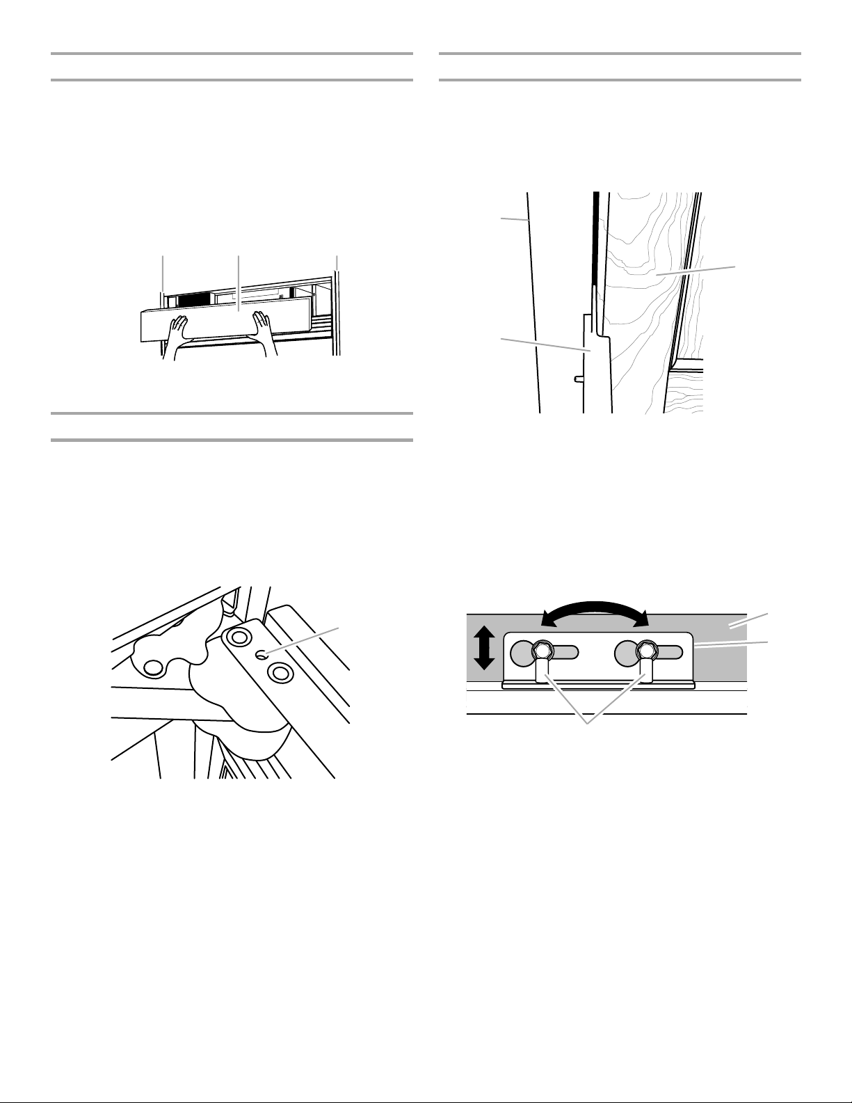
Installation du panneau de la grille supérieure
C
A
B
Achever l'installation
Installation standard - Grille affleurante
1. Accrocher les supports de panneau sur les boulons de
montage qui dépassent du sommet du réfrigérateur.
2. Tirer légèrement le panneau de grille vers le bas pour le
bloquer en place.
Installation intégrée - Grille de pleine hauteur
1. Aligner le support sur les boulons de montage.
2. Pousser le panneau de la grille vers l’avant jusqu’à ce que le
support s’emboîte.
B BA
A. Panneau de la grille supérieure
B. Côtés des placards
Réglage de l’ouverture de la porte
Il sera peut-être nécessaire de régler l’ouverture de la ou des
porte(s). S’assurer que la/les porte(s) peut/peuvent s’ouvrir
librement. Si la largeur d’ouverture de la/des porte(s) est trop
grande, installer la goupille de butée de porte (fournie).
1. Maintenir la porte à une position inférieure à 90°.
2. Insérer la goupille de butée de porte dans la charnière
supérieure, au trou indiqué.
3. À l’aide d’une clé Allen de ⁵⁄₃₂", serrer la goupille de butée de la
porte.
1. Utiliser la cale d’installation pour mesurer l’espace entre les
panneaux décoratifs et les placards adjacents.
■ Un dégagement de ³⁄₈" (0,95 cm) est nécessaire entre les
panneaux en acier inoxydable et les placards. Entre la
porte du congélateur et celle du réfrigérateur et entre les
portes et la grille supérieure, un dégagement de ¹⁄₈"
(0,32 cm) doit être respecté.
A
B
A. Placard adjacent
B. Cale d'installation
C. Panneau décoratif sur porte
2. Ajuster le panneau pour obtenir l’espacement nécessaire ou
pour l’alignement.
IMPORTANT : Si des ajustements sont nécessaires, ajuster le
panneau et non la porte.
■ Faire glisser le panneau décoratif d’un côté à l’autre dans
la fente en forme de trou de serrure.
■ Utiliser une clé Allen pour élever ou abaisser les tiges de
réglage afin de permettre au panneau de porte de pivoter.
A. Trou pour goupille de butée
A
C
A. Panneau de porte
B. Support de montage
C. Tiges de réglage
3. Percer au préalable des avant-trous de ¹⁄₈" dans le ou les
panneau(x) de porte en passant par les trous ouverts des
charnières inférieure et supérieure.
61

4. À l’aide des vis à tête hexagonale fendue (fournies), fixer les
A
B
charnières supérieures et inférieures aux panneaux de porte.
Bien serrer toutes les vis du panneau de porte.
REMARQUE : Pour les modèles de 36", un support
supplémentaire sur la partie supérieure sert à fixer le panneau
décoratif à la porte. Insérer les vis dans le support sur le
panneau de porte.
BA
DC E
A. Charnière supérieure
B. Support de montage réglable
C. Trous pour les vis
5. Si nécessaire, ajuster le panneau du tiroir pour l'aligner et bien
serrer toutes les vis du panneau.
D. Tiges de réglage de porte
E. Modèles de 36" uniquement
- Trous pour les vis
A
B
Installation des poignées
(Modèles avec ensemble de panneaux
uniquement)
IMPORTANT : Installer les poignées après que les panneaux de
porte aient été installés.
Outillage nécessaire : Clé Allen de ³⁄₃₂"
1. Localiser les trous situés à l’emplacement de l’installation des
goujons de montage de la poignée, dans les panneaux de
porte.
2. Fixer les goujons de montage de la poignée aux panneaux de
porte.
3. Installer les poignées sur les goujons de montage de la
poignée et serrer les vis de blocage.
REMARQUE : Selon la poignée, les vis de blocage peuvent
soit correspondre à une pièce indépendante, soit faire partie
du goujon de montage.
Installation de la grille de la base
La grille de la base comporte deux pièces pour permettre un
ajustement personnalisé : la grille de la base elle-même et la
plinthe. La plinthe peut être ajoutée à la grille de la base pour la
prolonger jusqu'au plancher.
1. Pour voir si la plinthe est nécessaire, placer la grille de la base
en position. Ne pas fixer la grille de la base au réfrigérateur.
Mesurer la distance entre le fond de la grille de la base et le
plancher. L'espace doit mesurer au moins ½" (1,27 cm) pour
que l’on puisse ajouter la plinthe.
REMARQUE : Si l'espace mesure moins de ½" (1,27 cm),
omettre les étapes 3 et 4 des instructions et installer
uniquement la grille de la base.
2. Enlever la pellicule de protection de la grille de la base.
3. Emboîter la plinthe sur la grille de la base.
A. Panneau décoratif du tiroir
B. Support de montage du panneau
6. À l’aide des vis à tête hexagonale fendue (fournies), fixer les
panneaux de porte aux garnitures de la porte du côté
charnière. Utiliser ces vis pour chaque côté.
7. À l’aide de vis à tête plate Phillips (fournies), installer la
garniture de porte du côté poignée.
8. Serrer complètement les vis fixant les brides de montage
situées au bas des portes, aux panneaux décoratifs.
9. Réinstaller la garniture supérieure de porte et le couvre-
charnière.
10. Emboîter le cache de la tige de réglage (fourni).
62
A. Grille de la base
B. Plinthe

4. Entailler la plinthe en marquant la rainure en V appropriée avec
un couteau utilitaire. Briser la plinthe au niveau de la ligne
d'entaille.
A
A. Rainure en V
5. À l'aide des deux vis, fixer la grille de la base au réfrigérateur,
tel qu'illustré.
REMARQUE : Insérer d’abord la vis du côté droit.
A
A. Vis (2)
Achever l’installation
1. Tourner le robinet de la canalisation d'alimentation en eau à la
position “Open” (ouvert).
2. Tourner l'interrupteur du réfrigérateur à la position ON
(marche). Voir la section “Interrupteur d'alimentation On/Off
(marche/arrêt)” dans le Guide d’utilisation et d’entretien pour
les instructions. Attendre quelques minutes. Vérifier les
raccords de la canalisation d’eau pour voir s’il y a des fuites.
3. Retirer toutes les boîtes, tous les sachets de pièces et tous les
matériaux d'emballage de l'intérieur du réfrigérateur. Voir la
section “Nettoyage” dans le Guide d'utilisation et d'entretien
pour les instructions. Ôter la pellicule protectrice et le carton
de la grille et des portes ou du châssis de la porte, selon le
modèle.
4. Installer les tablettes et bacs dans les compartiments de
réfrigération et de congélation.
5. Les commandes sont préréglées à l'usine au réglage moyen.
S’assurer que le compresseur fonctionne bien et que toutes
les lampes s’allument.
6. Purger le système d’eau avant l’utilisation. Voir “Préparation
du système d’eau.”
Pour l'utilisation la plus efficace de votre nouveau réfrigérateur
encastré, lire le Guide d'utilisation et d'entretien. Conserver les
instructions d'installation et le Guide d'utilisation et d'entretien
près du réfrigérateur encastré pour s’y référer facilement.
Préparation du système d’eau
Veuillez lire avant d’utiliser le système d’eau.
Immédiatement après l’installation, suivre les étapes ci-dessous
pour vous assurer que le système d’eau est bien nettoyé.
1. Ouvrir la porte du congélateur et arrêter la machine à glaçons.
Pour le Style 1, soulever le bras de commande d'arrêt en
broche tel qu’indiqué sur l’illustration. Pour le Style 2,
déplacer l'interrupteur au réglage OFF (à droite) tel qu’indiqué
sur l’illustration. L'interrupteur On/Off (marche/arrêt) pour la
machine à glaçons est situé au côté supérieur droit du
compartiment du congélateur.
Style 1 – Modèles sans distributeur
Style 2 – Modèles avec distributeur
REMARQUE : Si votre modèle est muni d’un système de filtre à la
grille de la base, s’assurer que le filtre à la grille de la base est bien
installé et que la capsule est à la position horizontale.
Ne pas utiliser pour le filtrage d'une eau
microbiologiquement polluée ou de qualité inconnue en
l'absence d'un dispositif de désinfection adéquat avant ou
après le système. Les systèmes certifiés pour la réduction
de kyste peuvent être utilisés pour l'eau désinfectée qui
peut contenir des kystes filtrables.
2. Utiliser un récipient robuste pour appuyer sur le levier du
distributeur d’eau pendant 5 secondes, puis relâcher pendant
5 secondes. Répéter l’opération jusqu’à ce que l’eau
commence à couler. Une fois que l’eau commence à couler,
répéter l’opération (appui sur le levier du distributeur pendant
5 secondes puis relâchement pendant 5 secondes) pendant
2 minutes supplémentaires. Ceci permettra d’évacuer l’air du
filtre et du système de distribution d’eau. Une vidange
supplémentaire peut être nécessaire dans certains domiciles.
REMARQUE : Pendant l’évacuation de l’air, l’eau peut gicler
du distributeur.
3. Ouvrir la porte du congélateur et mettre en marche la machine
à glaçons. Pour le Style 1, abaisser le bras de commande
d'arrêt en broche. Pour le Style 2, déplacer l'interrupteur à la
position ON (à gauche).
■ Attendre 24 heures pour obtenir la première quantité de
glaçons.
■ Jeter les trois premières quantités de glaçons produites.
■ Selon le modèle que vous avez, vous pouvez vouloir
choisir la caractéristique de production maximale de
glaçons pour augmenter la production de glaçons.
63

W10231367A
© 2009.
All rights reserved.
Todos los derechos reservados.
Tous droits réservés.
® Registered Trademark/™Trademark of Jenn-Air, U.S.A. Used under license by Maytag Limited in Canada.
® Marca registrada/™Marca de comercio de Jenn-Air, U.S.A. Usada bajo licencia por Maytag Limited en Canadá.
® Marque déposée/™Marque de commerce de Jenn-Air, É.-U. Emploi sous licence par Maytag Limited au Canada.
Printed in U.S.A.
Impreso en EE.UU.
Imprimé aux É.-U.
3/09
 Loading...