

Jenn Air CER3520AAA, CER3520AAH, CER3520AAL, CER3520AAT, CER3540AAA Installation Instructions
...Page 1
INSTALLER: LEAVE THESE INSTRUCTIONS WITH THE I~PPLIANCE
THE MANUAL IS INTENDED TO ASSIST IN THE INITIAL INSTALLATION AND ADJUSTMENTS OF THE RANGE.
ccccccccc ccccc ccccc
INSTALL OR SERVICE THIS RANGE.
ADJUSTMENt ALTERATION SERVICE
CLEARANCE DIMENSIONS
For complete information in regard to installation of range. see figures 1 and 2 on page 2. For SAFETY
CONSIDERATIONS, do not install a range in any combustible cabinetry which is not in accord with the installation
clearances shown in figure 1 on page 2.
CAUTION: SOME CABINETS AND BUILDING MATERIALS ARE NOT DE:SIGNED TO WITHSTAND
THE HEAT PRODUCED BY THE NORMAL SAFE OPERATION OF A LISTED APPLIANCE.
DISCOLORATION OR DAMAGE, SUCH AS DELAMINATION, MAY OCCUR.
8101P120-60
(03-95-00)
~
Page 2
A. Do not attempt to operate this oven with the door open
since open-door operation can result in harmful
exposure to microwave energy. It is important not to
defeat or tamper with the safety interloc:ks.
B. Do not place any object between the oven front face
and the door or allow soil or cleaner residue to
accumulate on sealing surfaces.
c
Do not operate the oven if it is damaged. It is
particularly important that the oven door close
properly and that there is no damage to the: (1) Door
(bent), (2) hinges and latches (broken or loosened),
(3) door seals and sealing surfaces.
D
The oven should rlot be adjusted or repaired by
anyone except properly qualified service personnel. I
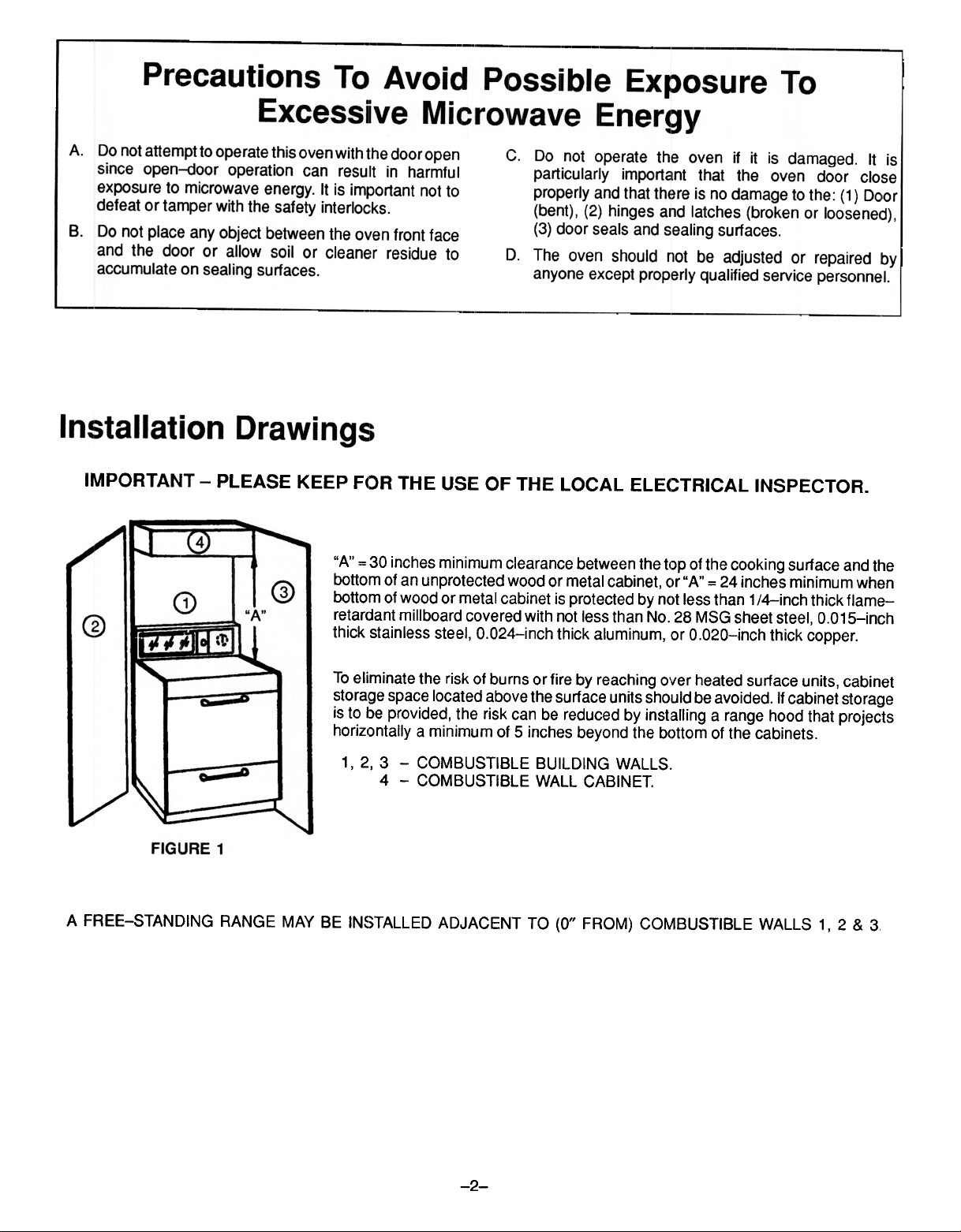
IMPORTANT -PLEASE KEEP FOR THE USE OF THE LOCAL ELEC:TRICAL INSPECTOR.
"A" = 30 inches minimum clearance between the top of the cooking surface and the
bottom of an unprotected wood or metal cabinet, or "A" = 24 inches minimum when
bottom of wood or metal cabinet is protected by not less than 1 /4-inch thick flame-
retar(jant millboard covered with not less than No. 28 MSG sheet steel, 0.015-inch
thick stainless steel, 0.024-inch thick aluminum, or 0.020-inch thick copper.
To eliminate the risk of burns orfire by reaching over heated surface units, cabinet
storage space located above the surface units should be avoided. If cabinet storage
is to be provided, the risk can be reduced by installing a range hood that projects
horizontally a minimum of 5 inches beyond the bottom of the cabinets.
1, 2, 3 -COMBUSTIBLE BUILDING WALLS.
4 -COMBUSTIBLE WALL CABINET.
A FREE-STANDING RANGE MAY BE IN~)TALLED ADJACENT TO (0" FROM) COMBUSTIBLE WALLS 1, 2 & 3
-2-
Page 3
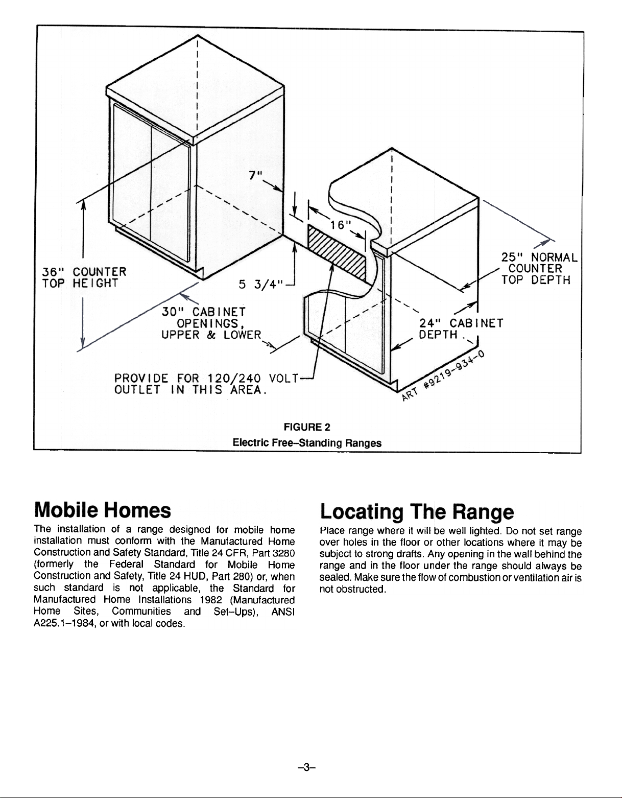
1611
36'1 COUNTER
TOP HEIGHT
5 3/411
3011 CAB I NET
OPENINGS.
UPPER & LOWER
PROVIDE FOR 120/240 VOLT
OUTLET IN THIS AREA.
Electric Free-Standing Ranges
The installation of a range designed for mobile home
installation must conform with the Manufactured Home
Construction and Safety Standard, Title 24 CFR, Part 3280
(formerly the Federal Standard for Mobile Home
Construction and Safety, Title 24 HUD, Part 280) or, when
such standard is not applicable, the Standard for
Manufactured Home Installations 1982 (Manufactured
Home Sites, Communities and Set-Ups), ANSI
A225.1-1984, or with local codes.
FIGURE 2
Place range where it will be well lighted. Do not set range
over holes in the floor or other locations where it may be
subject to strong drafts. Any opening in the wall behind the
range and in the floor under the range should always be
sealed. Make sure the flo~' of combustion or ventilation air is
not obstructed.
"j
~ TOP DEPTH
""
"-
2411 CAB I NET
DEPTH. I
r'
25 II NORMA L
COUNTER
"'-
-3-
~~
Page 4

WARNING: A risk of range tip-overexists if the appliance
is not installed in accordance with the installation
instructions provided. The proper use of this device
minimizes the risk of TIP-oVER. In using this device the
consumer must still observe the safety precautions as stated
in the USE and CARE MANUAL and avoid using the oven
door and/or lower drawer as a step stool.
B.
Cement or Concrete Construction:
1. Suitable screws for concrete construction can be
obtained at a hardware store. Drill the required size
hole forthe screws obtained into the concrete at the
center of the hole:s identified in figures 3 through 6,
as applicable, as "holes for floor." Secure the
ANTI-TIP bracket to the floor. Proceed to STEP 3.
Installation instructions are provided for wood and cement
installation in either floor or wall. Any other type of
construction may require special installation techniques as
deemed necessary to provide adequate fastening of the
ANTI-TIP bracket to the floor or wall. The bracket may be
installed to engage the left or right rear levelin!~ leg.
STEP 1 -Locating The Bracket (see figure 3)
Installations with flush mount wall outlet
A. Mark the floor or wall where either the right or left rear
"EDGE" of the range is to be located.
B. Place the BRACKET 15/16" from the marked "EDGE"
toward center of opening and against the back wall as
shown in figure 3.
C. Use the bracket as a template and mark the required
holes, as shown in figure 3, for the type of construction
you will be using.
Installations with alternate outlet locations (see figures
4 through 6.)
A. Mark the floor or wall where either right or left rear
"EDGE" of the range is to be located.
B. Place the bracket 15/16" from the marked "EDGE"
toward the center of opening and against the spacer as
shown in figures 4 through 6, as applicable. (See figures
4 through 6 for information on appropriate spacer sizes.
See figure 8 for information on securing of spacer.)
C. Use the bracket as a template and mark the required
holes, as shown in figure 4 through 6, for the type of
construction you will be using.
STEP 3 -Range Installation
A.
Complete the installation of the range per the installation
instructions provided \Nith the product.
B.
Align the range to its designated location and slide it
back into position. Make sure that the leveling foot is fully
inserted into and secured by the ANTI-TIP bracket.
Note: A minimum clearance of 1/4" is required between
the range and the leveling foot that will engage the
ANTI-TIP bracket, see figure 7 or 8.
CAUTION: Damage to the range may occur if range is
moved or lifted by grasping the main top or backguard.
c
All free-standing ranges with a glass top have a nonlift-up top. Coil tops are lift-up.
D
For SAFETY CONSIDERATIONS as well as optimum
performance adjust the range so that it is level. This may
be checked by placing a spirit level or a large pan of
water on the cooktop or the oven rack. If an adjustment
is required pull the range forward, tip the range and
rotate the leveling feet as required.
Eo
To check the range for proper installation of the anti-tip
bracket: Use a flashlight and look underneath the
bottom of the range to see that one of the rear leveling
legs is engaged in the bracket slot.
F.
Proceed with the Iremainder of the installation
instructions provided with the range.
STEP 2 -Anti-Tip Bracket Installation
A. Wood Construction:
1. Floor: Locate the center of the two holes identified in
figures 3 through 6, as applicable, as "holes for
floor." Drill a 1/8"pilot hole in the center of each hole
(a nail or awl may be used if a drill is not available.)
Secure the ANTI-TIP bracket to the floor with the
two screws provided. Proceed to STEP 3.
2. Wall: Locate the center of the two holes identified in
figures 3 through 6, as applicable, as "holes for
wall." Drill an angled 1/8" pilot hole in the center of
each hole as shown in figure 7 or 8 (a nail or awl may
be used if a drill is not available.) Secure the
ANTI-TIP bracket to the wall with the two screws
provided as shown in figure 7 or 8. Proceed to STEP
3.
-A.-
Page 5

~3/8. SPACER BLOCK WI LL
REQUIRED BEHIHD THE AHTI
BRACKET. NAI L DR SCREW \WJOOEN \
sPACER BLOCK CNOT PROVIDED)
.,--,3(1
3 1/2,,1
ANTI-TIP
BRACKET
\
"'",. ..-
HOLES FOR-J'" ""- -15/16" FRO~ EDGE OF RANGE
~ARKED EOOE '~
OF RANGE FIGURE 6
MARKED EDGE
OF RANGE
..2 NAILS OR SCREWS
~;~~~~~~8 " /: ?' ~~~
\
FLOOR'" , ~
~
--~--":ATTACH TIE-oO~ BRACKET
\.../~'
LTO WALL STRUCTURE.
rL
~
III
"".
"1.1.
WITH LDNG SCREWS.
~OLES FOR WALL
~EVEL I NG FOOT
"
LOOR
~
~
~
NOTE: USE A MINIMUM OF (2) SCREWS
TO INSTALL BRACKET TO THE
WALL OR FLOOR.
BRACKET -
-1/4"MlN.
SlIDE IN TO SECURE
FIGURE 7
"
"
"
~---
ART,A219-761B
""'---,.-
SCRI:WS MUST
~NTI:R WOOD OR
NET~\L
><
./
-5-
WOODEN SPACER
RANGE ANTI-TIP~ nl
BOTTOM BRACKET --'1 r
SCREW BRACKET
TO SPACER
SLIDE IN TO
~
USE A MINIMUM OF TWO (2)
10d x 3" LONG NAILS O~
LONG SCREWS TO ANCHOR
SPACER TO WALL. PLATE.
FIGURE 8
NAILED TO
WALL PLATE
-WALL PLATE
~~
1./
ART .$21$-$20-A
'-
Page 6

ELECTRIC SUPPLY
The range must be installed in accordance with Local and
National Electric Code (NEC) ANSI/NFPA No. 70-1993.
See rating plate on front of range for total connected kw
rating.
OUTSIDE WIRING
Your local utility company will tell you whether the present
electric service to your home is adequate. It may be
necessary to increase the size of the wiring to the house and
service switch to take care of the electrical load demanded
by the range. The kilowatt rating forthe range is specified on
the name plate on the range.
HOUSE WIRING
Most local Building Regulations and Codes require that all
electrical wiring be done by licensed electricians. All wiring
should conform to Local and National Electrical Codes. This
range requiresasingle phase three wire 120/240 volt,60 Hz,
AC circuit. Wiring codes require a separate circuit be run
from the main entrance panel to the range and that it be
equipped with separate disconnect switch and fuses, either
in the main entrance panel or in a separate switch and fuse
box. In some communities, a solid or flexible continuous
armored conduit must be used from main entrance panel to
the terminal box on the rear of the range. Others will permit
the termination of the range circuit at a polarized three orfou r
wire plug-in outlet placed at a convenient point near the
back of the range. The range is then connected to this outlet
through an approved service cord (pigtail) fastened securely
to the terminal block with proper strain relief at the range and
a three or four pronged plug at the opposite end.
RANGE CONNECTIONS
On models using service cords (Pigtail) the front surface of
the range outlet must be mounted flush to wall. See figures
10A and 10C.
On models not provided with a service cord and models
having a conduit, connection to the power supply is
necessary. REMEMBER -mobile homes and some LOCAL
CODES DO NOT PERMIT GROUNDING THROUGH
NEUTRAL. Hence, 4-wire service MUST be provided for
such installations. All others permit 3-wire service, use
COPPER WIRE ONLY. Make connections as explained
below and with reference to the appropriate illustration. (See
figures 10A thru 100). After installation, insure tightness of
all electrical connections and replace all covers.
NOTE: For cord replacement -ONLY a power supply cord
rated at 240 volts minimum, 40 amperes or 50 amperes
power supply cord that is marked for use with nominal 1 3/8"
(34.93 mm) diameter connection opening, with closed loop
terminals and marked for use with ranges shall be used.
,. A£U6'T TIE REAR LEG LEVELE/?S TO TIEl/? C{RRECT fEIGHT.
2. A£U6'T TIE FRCWT LEG LEVELE1?S TO AN APPROX. fEIGHT.
3. POSITlOO TfE /?AIa' IN TJo£ CUTOOT.
4. MAKE FINAL AD.AJST~NT TO FroYT LEG LEVELERS.
.0'. RAISE FRCWT r:I'" RAIa -SLIOC TI£ BASE COVER (C1>TI~
EOOIP1£NT) LIa"R TIE LEG LEVELERS (SEE ILLUSTRA TICW) .
-INSTALLATION OF FRONT FLOOR COV£R-
OPTIONAL EOUIPMENT
-6-
Page 7

Remove terminal block access cover from range back. (See
figure 9).
For service cord (pigtail) use, remove knockout ring from
conduit plate. (See figures 10A and 10C).
3. Both the white wire and the uninsulated (bare) wire from
the conduit should connect to the white service wire as
shown. The bare wire is the range chassis ground.
4-WIRE SERVICE CORD INSTAllATION
(MOBILE HOMES) FIGURE 1 DC
1. The copper ground strap connected between the neutral
(middle) post of the main terminal block and the chassis
MUST be removed and discarded. Keep the green
ground screw. Only a 4 conductor cord should be used.
2. The green wire from the service cord must connect to the
range chassis using the green ground screw.
3. The white wire of the service cord must connect to the
neutral (middle) post of the main terminal block. The
other two wires of the service cord connect to the red and
black posts of the main terminal block, respectively.
4. Position the strain relief with flanges on top of conduit
plate as shown and secure to service cord.
4-WIRE CONDUIT INSTAllATION
(MOBILE HOMES) FIGURE 100
3-WIRE SERVICE CORD INSTAllATION
FIGURE 10A
1. Insure that the copper ground strap IS CONNECTED
between the middle post of the main terminal connection
block and the range chassis.
2. The middle wire of the service cord MUST connect to the
neutral (middle) post of the main terminal connection
block. The other two wires of the service cord connect to
the outside posts of the main terminal connection block.
Polarity is unimportant.
3. Position strain relief with flanges on top of conduit plate
as shown and secure to service cord.
3-WIRE CONDUIT INSTAllATION
FIGURE 10B
1. The range conduit must be routed and properly
connected to an approved electrical junction box behind
the range.
2. The red and black wires from the range conduit must
respectively connect to the red and black service wires.
An approved wire connector must be used.
1. The range conduit must be routed and properly
connected to an approved electrical junction box behind
the range.
2. The red and black wires from the range conduit must
respectively connect to the red and black service wires.
An approved wire connector must be used.
3. The white wire from the conduit must be connected to the
white service wire.
4. The uninsulated (bare) wire from the conduit must be
connected either to a green or bare service wire.
CONVERSION FRO~t 3-WIRE TO 4-WIRE
SERVICE
(Free-Standing Models Only With 3-Wire Service Cord
Attached).
Disconnect range from power. Remove the access cover on
back of range and remove the 3-wire service cord from the
main terminal block. Follow instructions as outlined in figure
10C to connect the 4-wire service cord.
NOTE: Cord replacement -ONLY a power supply cord
rated at 240 volts minimum, 40 amperes or 50 amperes
power supply cord that is marked for use with nominal 1 3/8"
(34.93 mm) diameter connection opening, with closed loop
terminals and marked for use with ranges shall be used.
-7-
Page 8

FIGURE 10A
NORMAL -3 WIRE PLUG
RED-,
APPROVED CONNECTORS
APPROVED BOX'"
RED
WHITE
FIGiURE 108
NOR~IIAL -3 WIRE CONDUIT
--~r-
~~~._.:~ ~.: ANGE CONDU I T
.-~APPROVED
~- CONNECTOR
A,
ACK
L 1 (RED)~V~
NEUTRAL
ART.
9219-749-A
GROUND
2 (BLACK)
CIRCUIT
(POWER SUPPLY)
WIRING METHOD IF CODE DOES
NOT PERMIT GROUNDING THROUGH
NEUTRAL CONDUCTOR & ALSO
REQUIRED IN MOBILE HOMES.
FIGURE 10C
MOBILE HOME -4 WIRE PLUG
MOBILE HOME: -4 WIRE CONDUIT
FIGURE 10D
-8-
~
 Loading...