

Page 1
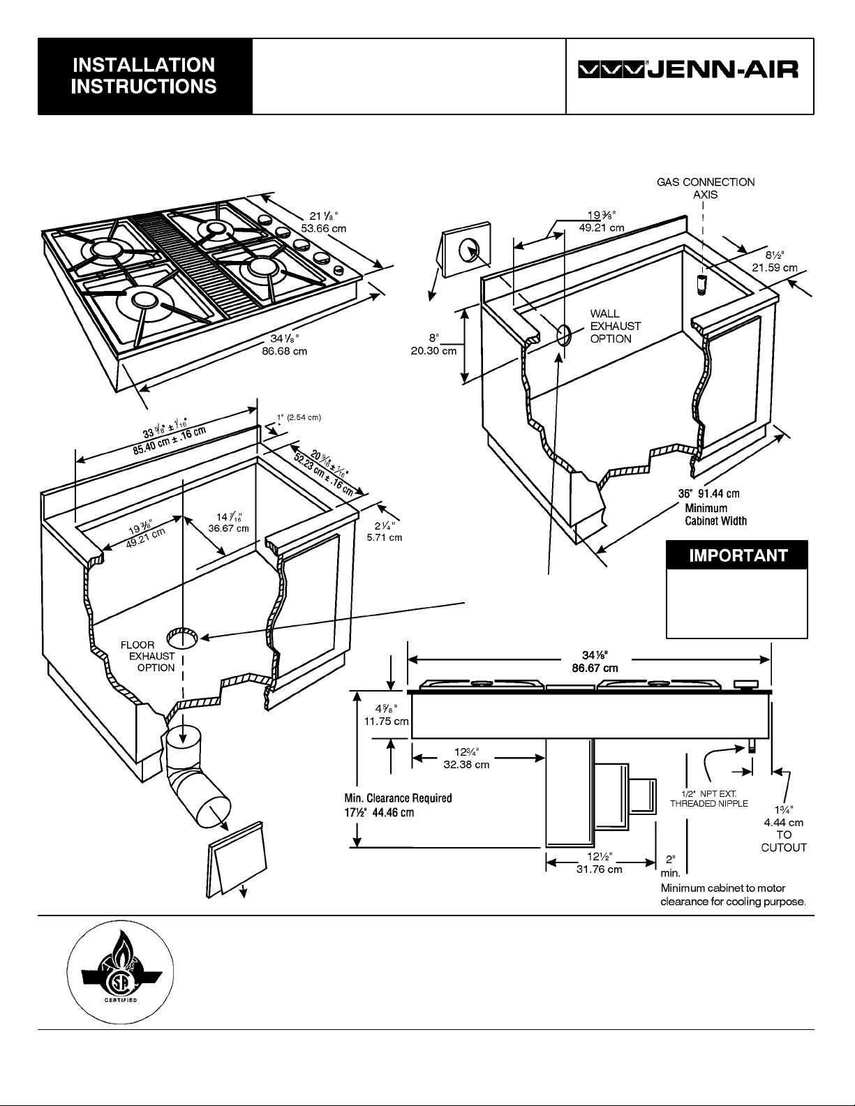
EXPRESSIONS
GAS COOKTOP
IMPORTANT: Installationshouldbeperformedonlyby aJenn-Air AuthorizedServicer orother qualifiedinstaller. Read safety
precautions in the Use & Care Manual before using this appliance.
(Dimensions shown in both inches and centimeters.)
403 WEST FOURTH STREET, NORTH · NEWTON, IA 50208
SELECT APPROPRIATE
DUCT CUTOUT
(SEE DUCTING
INSTRUCTIONS.)
CUTOUT
DIMENSIONS
ARE
CRITICAL
INSTRUCTIONS TO INSTALLER:
S Side Clearance -Unit may besafely installed asnear as 2² (5.08 cm) from a side wallif space
limitations require. However, a side clearance of at least 6² is recommended for optimum
ventilation.
SAVE THESE INSTRUCTIONS FOR FUTURE REFERENCE
8101P575-60
(04-04-00)
Page 2
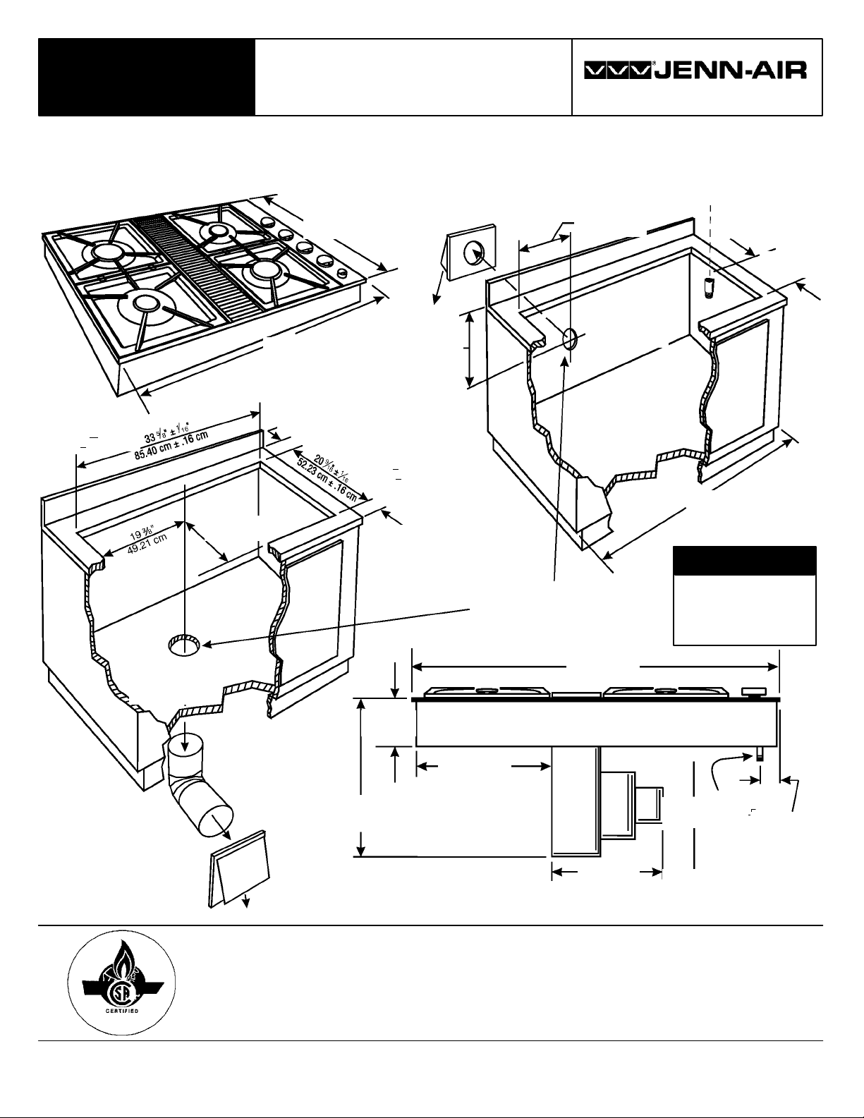
INSTRUCCIONES
DE INSTALACIÓN
SUPERFICIE PARA
COCINAR DE GAS
403 WEST FOURTH STREET, NORTH · NEWTON, IA 50208
EXPRESSIONS
IMPORTANTE: La instalación debe realizarla un técnico autorizado de Jenn-Air u otro instalador calificado. Lea las
“Instrucciones de seguridad” en el libro de Uso y cuidado antes de usar el electrodoméstico.
85.40 cm + 0.16 cm
(33 5/8 +
1/16 pulg)
49.21 cm
(19 3/8 pulg)
(Las dimensiones se muestran en pulgadas y centímetros.)
53.66 cm
(21 1/8 pulg)
20.3 cm
(8 pulg)
1/16 pulg)
5.71 cm
(2 1/2 pulg)
SELECCIONE EL CORTE
ADECUADO DE DUCTOS
(VEA LAS INSTRUCCIONES
DE LOS DUCTOS).
36.67 cm
(14 7/16 pulg)
86.68 cm
(34 1/8 pulg)
2.54 cm (1pulg)
52.23 + 0.16 cm
(209/16+
EJEDELA
CONEXIÓN DE GAS
49.21 cm
(19 3/8 pulg)
21.59 cm
(8 1/2 pulg)
OPCIÓN DE
ESCAPE POR
LA PARED
91.44 cm (36pulg)
Anchura mínima
del gabinete
IMPORTANTE
LAS DIMENSIONES
DEL HUECO SON
IMPORTANTES
OPCIÓN DE
ESCAPE
POR EL
PISO
86.67 cm
(34 1/8 pulg)
11. 75 c m
(4 5/8 pulg)
32.38 cm
(12 1/2 pulg)
Espacio libre mínimo necesario
44.46 cm (17 1/2 pulg)
31.76 cm
(12 1/2 pulg)
NIPLEDEROSCA
EXTERNA DE
1/2 PULG. NPT
5.08 cm (2pulg) mín.
Espacio libre mínimo del
gabinete al motor parafines
de enfriamiento.
4.44 cm
(1 3/4 pulg)
AL CORTE
INSTRUCCIONES PARA EL INSTALADOR:
S Espacio libre lateral - Launidad puedeinstalarse de manera segura inclusoa 5.08cm (2pulg)
de lapared lateral si laslimitaciones de espaciolo requieren. Sinembargo, se recomiendaun
espacio libre lateral de cuando menos 15.24 cm (6 pulg ) para obtener la ventilación óptima.
CONSERVE ESTAS INSTRUCCIONES COMO REFERENCIA FUTURA
Page 3
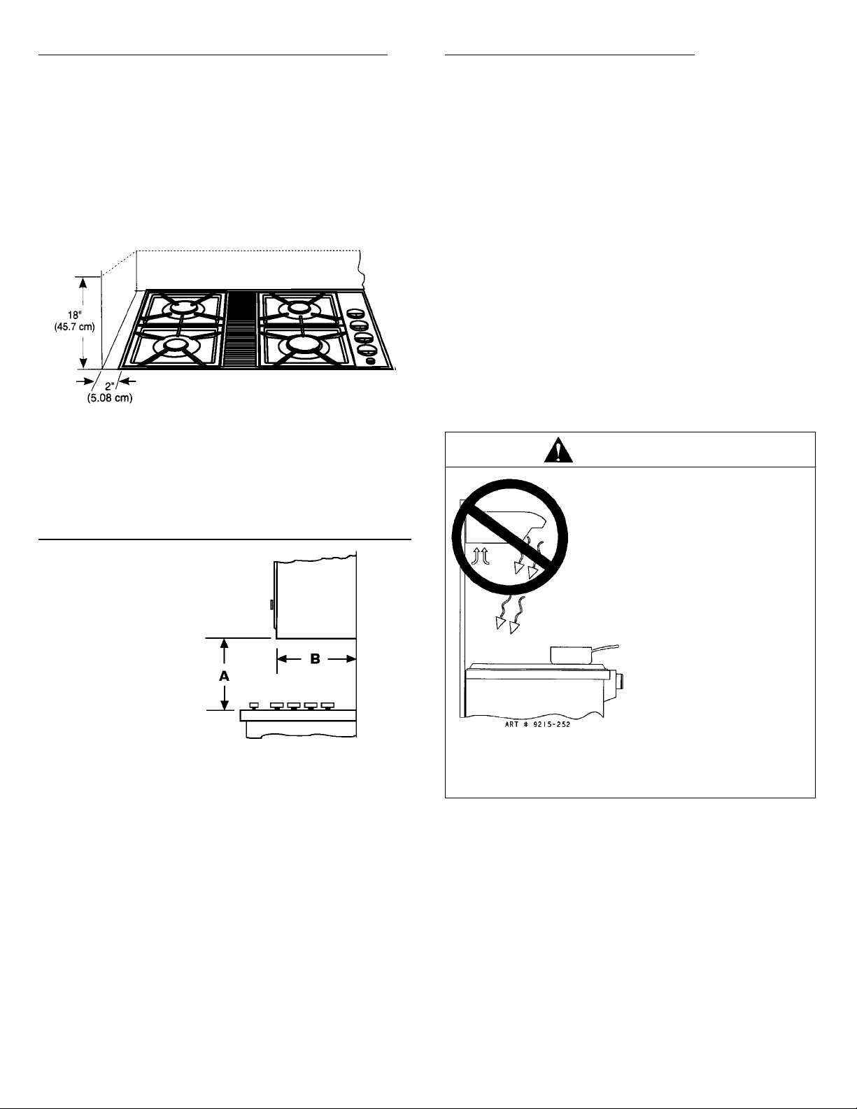
Location Of Your Jenn-Air Appliance
Locate this appliance away from combustible materials such
as window curtains and combustible wall decorations. The
minimum horizontal clearance between the edge of the
appliance and adjacent combustible construction is:
S 0.75 inches (1.90 cm) at rear;
S 2 inches (5.08 cm) at sides
Preparation Of Countertop
The cutout in the countertop into which the appliance is to
be installed should be prepared according to the cutout
dimensions given on page 1 of these instructions.
CAUTION: Cutout dimensions are critical. Dimensions must
be measured and cut accurately to within ± 1/16² to ensure
proper fit.
These minimum clearances pertain to vertical surfaces
between the countertop level and a level 18² above the
countertop.
Figure 1: Minimum Horizontal Clearance
NOTE: These are not recommended clearances, but rather
the minimum allowable clearances. Overall performance of
your cooktop will be enhanced by providing a 6² or greater
clearance on either side of the unit.
Installing Cabinetry Over Your Cooktop
Observe the following clearances
to overhead cabinetry.
Important Installation Suggestions:
1. Chamfer all exposed edges of decorative countertop
laminate to prevent damage from chipping.
2. Slightly radius corners of cutout and file to insure smooth
edges and prevent corner cracking.
3. Rough edges, inside corners which have not been
rounded and forced fits can contribute to cracking of the
countertop laminate.
4. Unit must be supported on all four sides by the
countertop and countertop must be supported within 3² of
edge of cutout.
WARNING
THIS PRODUCT SHOULD NOT
BE INSTALLED BELOW A
VENTILATION TYPE HOOD
SYSTEM THAT DIRECTS AIR
IN A DOWNWARD DIRECTION.
(SEE FI GURE)
Figure 2
Minimum Clearances to
Overhead Cabinetry
A = 30 inches (76.2 cm) minimum vertical clearance
between cooking surface and combustible
construction or metal cabinets above the appliance.
This clearance may be reduced to not less than 24
inches by protecting the underside of the combustible
material or metal cabinet above the cooking surface
with not less than 1/4-inch insulating millboard
covered with sheet metal not less than 0.0122-inch
thick.*
B = 13 inches (33.0) maximum depth of cabinets installed
above cooking surface.
CAUTION: Avoid use of cabinets above cooktop for storage
to eliminate potential hazard of reaching over open flames.
THESE SYSTEMS MAY CAUSE
IGNITION AND COMBUSTION
PROBLEMS WITH THE GAS
BURNERS RESULTING IN
PERSONAL INJURY AND MAY
AFFECT THE COOKING
PERFORMANCE OF THE UNIT.
NOTE: THE FIGURE MAY NOT ACCURATELY REPRESENT YOUR
RANGE OR COOKTOP; HOWEVER, THIS WARNING APPLIES TO
ALL GAS COOKING PRODUCTS.
*Jenn-Air Over-the-Range microwave ovens (model #M418 and M438) have been listed by UL for use over Gas and Electric Ranges. When properly
installed ataminimum height of66inches fromthefloorto the top ofthemicrowave, the clearance to thecooking surfaceatthe center will be 13-3/4 inches.
2
Page 4
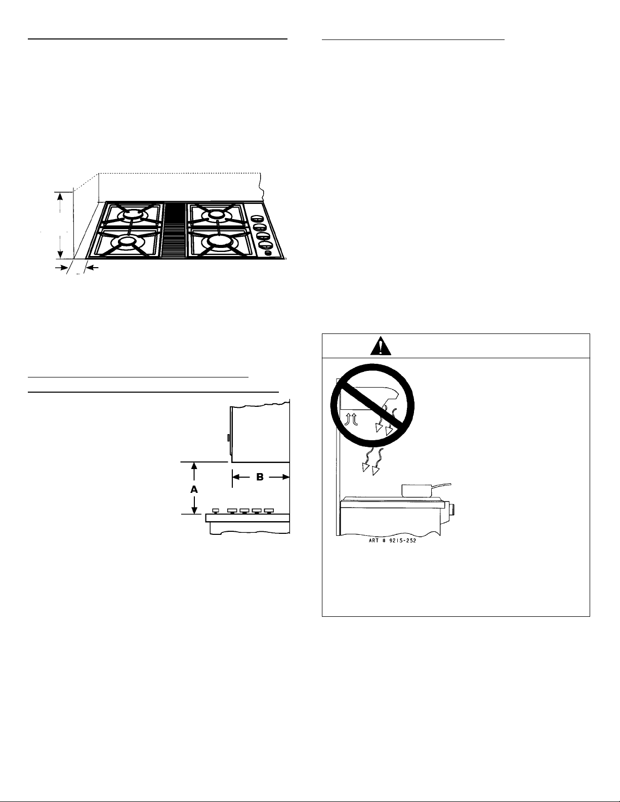
Ubicación del electrodoméstico Jenn-Air
Coloque este electrodoméstico alejado de materiales
combustibles como cortinas de ventanas y decoraciones
combustibles de la pared. El espacio libre mínimo
horizontalmente entre el borde del electrodoméstico y la
construcción combustible adyacente es:
S 1.90 cm (0.75 pulg) en la parte posterior;
S 5.08 cm (2 pulg) a los lados
Estos espacios libres mínimos se refieren a las superficies
verticales que están entre el nivel del mostrador y a un nivel
de 45.7 cm (18 pulg) sobre el mostrador.
45.7 cm
(18 pulg)
5.08 cm
(2 pulg)
NOTA: Éstos no son los espacios libres recomendados,
sino los espacios libres mínimos permitidos. El
funcionamiento general de la superficie para cocinar
mejorará si se proporciona un espacio libre de 15 cm
(6 pulg) o mayor a cada lado de la unidad.
Figura 1: Espacio libre mínimo horizontalmente
Preparación del mostrador
El hueco del mostrador de la cocina en el que se instalará
el electrodoméstico deberá prepararse de acuerdo con las
dimensiones de corte que aparecen en la página 1 de estas
instrucciones.
PRECAUCIÓN: Las dimensiones del hueco son muy
importantes. Las dimensiones deben medirse y cortarse
con precisión de entre 0.159 cm (± 1/16 pulg) para
garantizar el ajuste apropiado.
Sugerencias importantes de instalación:
1. Achaflane todos los bordes expuestos del laminado
decorativo del mostrador para evitar que se dañe con
astilladuras.
2. Redondee levemente las esquinas del hueco y líjelas
para garantizar que los bordes estén lisos y evitar que se
quiebren las esquinas.
3. Los bordes burdos en las esquinas interiores que no se
hayan redondeado y los ajustes forzados pueden
contribuir a que se agriete el laminado del mostrador de
la cocina.
4. La unidad debe estar apoyada por los cuatro lados por el
mostrador y éste, debe estar apoyado a una distancia
menor de 7.5 cm (3 pulg) del borde del hueco.
ADVERTENCIA
Instalación de los gabinetes por
encima de la superficie para
Observe los siguientes espacios
libres a los gabinetes superiores.
Figura 2
Espacios libres mínimos a los
gabinetes superiores
A= 76.2 cm (30 pulg) de espacio vertical mínimo entre la
superficie para cocinar y la construcción combustible
o los gabinetes de metal encima del electrodoméstico.
Este espacio libre no puede reducirse a menos de
60.96 cm (24 pulgadas) si se protege la parte inferior
del material combustible o del gabinete de metal que
se encuentre encima de la superficie para cocinar con
no menos de 0.635 cm (1/4 pulg) de cartón grueso
aislante recubierto con una hoja de metal de no
menos de 0.0122 pulgadas de grosor.*
B= 33.02 cm (13 pulg) de profundidad máxima de los
gabinetes instalados por encima de la superficie
para cocinar.
PRECAUCIÓN: Evite usar los gabinetes que están encima
de la superficie para cocinar para eliminar los peligros
potenciales al tratar de alcanzar algo por encima de las
llamas encendidas.
*Los hornos de microondas instalados encima deestufas Jenn-Air (modelos núm. M418 y M438) han sido listados por UL para usarse sobre estufas de gas y
eléctricas. Cuando seinstalan correctamente a unaaltura mínima de 168cm (66 pulg) delpiso a la parte superior delmicroondas, elespacio librea la superficie
de cocción en el centro será de34.9 cm (13-3/4 pulg).
cocinar
NOTA: ES POSIBLE QUE LA FIGURA NO SEA UNA REPRESENTACIÓN EXACTA DE SU ESTUFA O DE SU SUPERFICIE PARA
COCINAR; SIN EMBARGO, ESTA ADVERTENCIA SE APLICA A
TODOS LOS ELECTRODOMÉSTICOS DE COCINA A GAS.
2
ESTE PRODUCTO NO DEBE
INSTALARSE DEBAJO DE
UNA CAMPANA DE
VENTILACIÓN QUE DIRIJA EL
AIRE EN UNA DIRECCIÓN
HACIA ABAJO.
(VEA LA FIGURA)
ESTOS SISTEMAS DE
VENTILACIÓN PUEDEN
CAUSAR PROBLEMAS DE
IGNICIÓN Y DE
COMBUSTIÓN CON LOS
QUEMADORES A GAS
RESULTANDO EN LESIONES
PERSONALES Y PUEDEN
AFECTAR LA MANERA DE
COCINAR DE LA UNIDAD.
Page 5
Installation Of Appliance
Follow accompanying ducting instructions carefully.
This appliance is designed to always be vented outdoors.
This appliance should be ducted separately from other
vented appliances.
Connecting Appliance To Gas Supply
A QUALIFIED SERVICEMAN OR GAS APPLIANCE
INSTALLER MUST MAKE THE GAS SUPPLY
CONNECTION. Leak testing of the appliance shall be
conducted by the installer according to the
instructions given.
This appliance is designed for use with the gas appliance
pressure regulator provided.
The installation of this appliance must conform with local
codes or, in the absence of local codes, with the latest
edition of the National Fuel Gas Code, ANSI Z223.1 USA or
current CAN/CGA-B149 INSTALLATION CODE.
In The Commonwealth Of Massachusetts
This product must be installed by a licensed plumber or
gas fitter when installed within the Commonwealth of
Massachusetts.
A “T” handle type manual gas valve must be installed in
the gas supply line to this appliance.
A flexible gas connector, when used, must not exceed a
length of three (3) feet / 36 inches.
This appliance is designed to operate at a pressure of 5
inches of water column on natural gas or, if converted for
use with LP gas (propane or butane), 10 inches of water
column. Make sure this appliance is supplied with the type
of gas for which it is designed.
This appliance was adjusted at the factory for use with
natural gas. If, in the future, this appliance is to be used on
a different type of gas, all of the conversion adjustments
described on pages 4 and 5 must be made by a service
technician or other qualified person before attempting to
operate the cooktop on that gas. Natural gas should be
supplied to the appliance at a line pressure between 6 and
14 inches of water column or, if converted for LP gas,
between 11 and 14 inches.
WARNING: If the pressure of the gas system
supplying this appliance exceeds 14² W.C., an external
regulator (not provided) must be installed in the gas line
to reduce the system pressure to no more than 14² W.C.
Failure to do this can result in excessive gas flow and
explosion.
1. Install a manual shut-off valve in an accessible location in
the gas line external to this appliance for the purpose of
shutting off gas supply to this appliance.
2. Install the appliance pressure regulator supplied with this
appliance to the threaded gas inlet of the manifold pipe,
taking care to observe proper direction of gas flow
through the regulator. Tighten to 20 to 30 ft.-lbs. of
torque.
3. Connect the inlet of the appliance pressure regulator to
theshut-offvalveusinga1/2² NPT pipe nipple of
appropriate length and additional pipe fittings, as
required.
Use an approved pipe joint compound that is resistant to
the action of LP gas on all external pipe threads when
making these connections.
A new, A.G.A.-certified, flexible metal appliance connector
may be used to connect this appliance to the gas supply
(figure 3.) The flexible connector should have a diameter of
1/2² flare union adapter is required at each end of the
flexible connector. CAUTION: Do not attempt to attach the
flexible connector directly to an external pipe thread.
IMPORTANT
Apply a non-corrosive leak detection fluid to all joints and
fittings in the gas connection between the supply line
shut-off valve and the range. Include gas fittings and
joints in the range if connections were disturbed during
installation. Check for leaks! Bubbles appearing around
fittings and connections will indicate a leak. If a leak
appears, turn off supply line gas shut-off valve, tighten
connections, turn on the supply line gas shut off valve,
and retest for leaks. Never test for gas leaks with an
open flame.
NOTE: In Canada, gas utilization codes prohibit use of
street elbows. Use standard pipe elbows and make
modifications to these instructions as necessary.
Make sure your appliance is supplied with the type of gas
for which it is adjusted and that the gas is being supplied
within the appropriate pressure range.
WARNING
Gas leaks may occur in your system and result in a
dangerous situation. Gas leaks may not be detected by
smell alone.Gas suppliersrecommend you purchase and
install an UL approved gas detector. Install and use in
accordance with the manufacturer’s instructions.
3
Page 6
Instalación del electrodoméstico
Siga cuidadosamente las instrucciones adjuntas de los
ductos.
Este electrodoméstico está diseñado para ventilarse
siempre hacia el exterior. Este electrodoméstico debe tener
ductos independientes de los otros electrodomésticos.
Este electrodoméstico está diseñando para usarse con el
regulador de presión de gas provisto con él.
La instalación de este electrodoméstico debe estar en
conformidad con los códigos locales, o en caso que no
existan, con la última edición del Código Nacional de Gas
Combustible ANSI Z223.1 o el CÓDIGO DE INSTALACIÓN
actual CAN/CGA-B149
En el estad o de Massachusetts
Este producto debe instalarlo un plomero certificado o un
ajustador de gas cuando se instale dentro del estado de
Massachusetts.
Debe instalarse una válvula manual con asa tipo “T” en la
tubería de suministro de gas al electrodoméstico.
Los conectores flexibles de gas, cuando se usen, no
deben sobrepasar una longitud de 0.91 m (3 pies) /
91.44 cm (36 pulg).
Este electrodoméstico está diseñado para operar a una
presión de 5 pulgadas de columna de agua en gas natural
o, si se convierte a gas LP (propano o butano), de
10 pulgadas de columna de agua. Asegúrese de que este
electrodoméstico reciba el suministro del gas para el cual
se diseñó.
Conexión del electrodoméstico al
suministro de
LA CONEXIÓN DE GAS DEBE REALIZARLA UN
TÉCNICO CALIFICADO DE SERVICIO O UN
INSTALADOR DE ELECTRODOMÉSTICOS DE GAS. Las
pruebas de fugas del electrodoméstico deberá
realizarlas el instalador de acuerdo con las
instrucciones proporcionadas.
1. Instale una válvula de cierre manual en un lugar
accesible en la tubería externa de gas al
electrodoméstico con el fin de cerrar el suministro de gas
al electrodoméstico.
2. Instale el regulador de presión que se incluye con esto
electrodoméstico a la entrada roscada de gas de la
tubería del múltiple, con cuidado de mantener la
dirección correcta del flujo de gas a través del regulador.
Apriete a una torsión de 20 a 30 pulgadas por libra.
3. Conecte la entrada del regulador de presión a la válvula
de cierre usando un niple de tubería de 1/2 pulg NPT del
largo apropiado y los accesorios adicionales de tubería,
según sea necesario.
Use un compuesto de uniones de tuberías aprobado que
sea resistente a la acción del gas LP en todas las roscas
externas de la tubería cuando realice estas conexiones.
Puede usarse un conector metálico flexible, certificado por
AGA para conectar este electrodoméstico al suministro de
gas (figura 3). El conector flexible debe tener un diámetro
de 1/2 pulgada. Se requiere un adaptador de unión
abocinado a ambos extremos del conector flexible.
PRECAUCIÓN: No trate de sujetar el conector flexible
directamente a la rosca externa de la tubería.
gas
Este electrodoméstico se ajustó de fábrica para usarse con
gas natural. Si en el futuro, este electrodoméstico se usará
con un tipo diferente de gas, deberán realizarse todos los
ajustes mencionados en las páginas 4 y 5, un técnico u otra
persona calificada de servicio deberán realizar dichos
ajustes antes de tratar de operar la superficie para cocinar
con ese gas. El gas natural deberá suministrarse al
electrodoméstico a una presión de tubería de entre 6 y
14 pulgadas de columna de agua o, si se convirtió a gas
LP, a entre 11 y 14 pulgadas.
ADVERTENCIA: Si la presión del sistema de gas que
suministra al electrodoméstico sobrepasa las
14 pulgadas de columna de agua, deberá instalarse un
regulador externo (no incluido) en la tubería de gas para
reducir la presión del sistema a no más de 14 pulgadas
de columna de agua. No hacer esto, podría causar un
flujo excesivo de gas y una explosión.
Asegúrese de que el electrodoméstico esté recibiendo el
tipo de gas para el que fue ajustado y que el gas se esté
suministrando a la presión adecuada.
IMPORTANTE
Aplique un líquido de detección de fugas que sea
anticorrosivo en todas las uniones y los accesorios de la
conexión de gas entre la válvula de cierre de la tubería
de suministro y la estufa. Incluya los accesorios y las
uniones de gas en la estufa si se alteraron las
conexiones durante la instalación. ¡Revise si existen
fugas! Si aparecen burbujas alrededor de los accesorios
y las conexiones significará que hay una fuga. Si aparece
una fuga, cierre la válvula de suministro de la tubería de
gas, apriete las conexiones, abra la válvula de cierre de
la tubería de suministro de gas y vuelva a revisar las
fugas. Nunca realice pruebas de fugas con llamas
encendidas.
NOTA: En Canadá, los códigos de utilización de gas
prohíben el uso de codos del sector. Use codos de tubería
estándar y haga modificaciones a estas instrucciones
según sea necesario.
ADVERTENCIA
Puede ocurrir un escape de gas en su sistema yprovocar
una situación peligrosa. Los escapes de gas no pueden
ser detectados porel olorsolamente. Losproveedores de
gasrecomiendan quecompre einstale un detector de gas
aprobadoporellaboratorio UL. Instleloyúselodeacuerdo
con las instrucciones de fabricante.
3
Page 7
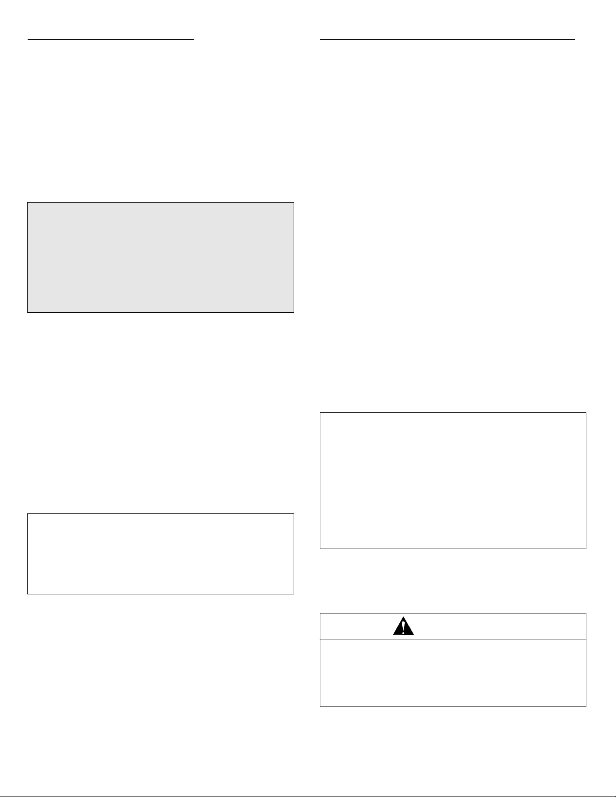
Connecting Appliance To Electricity
WARNING
Manifold Pipe
Appliance Pressure
Regulator, supplied
(Observe directionality
of Gas Flow)
Flare Union
Adaptor
Flexible
Appliance
Connector
(5 ft. max.)
Flare Union
Adaptor
Gas Shut-Off
Valve
1/2² NPT Pipe
Figure 3: Alternative Gas Connections
To Electrical
Outlet
To Blower Motor
1/2² NPT Pipe
Nipple
Gas Shut-Off
Valve
1/2² NPT Pipe
ELECTRICAL GROUNDING INSTRUCTIONS
This applianceis equipped witha three-prongedgrounding
plugforyourprotectionagainst shockhazardandshouldbe
plugged directly into a properly grounded receptacle.
Do not cut or remove the grounding prong from this plug.
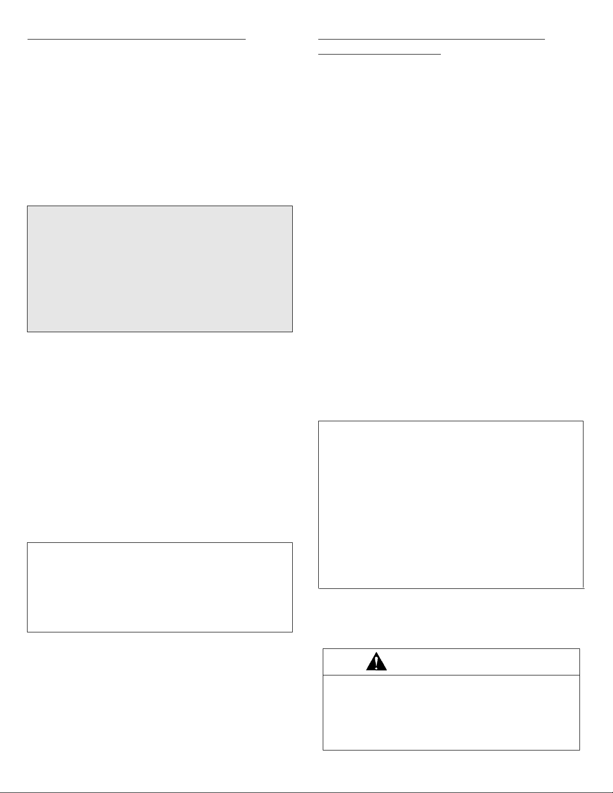
The electrical supply required is 110/120 Volts A.C., 60 Hz,
with 15 amp. circuit protection. This appliance is equipped
with a grounded type power cord. A grounded outlet must
be provided. It is recommended, for convenience, this outlet
be located in the shaded area in figure 4.
User may experience occasional circuit tripping if Ground
Fault Circuit Interrupter (GFCI) outlet or breaker is in use.
Pressure Testing
This appliance must be isolated from the gas supply piping
system by closing its individual manual shutoff valve during
any pressure testing of the gas supply piping system at test
pressures equal to or less than 1/2 PSIG (2.5 k pa).
This appliance, as well as its individual shutoff valve, must
be disconnected from the gas supply piping system during
any pressure testing of the system at test pressures in
excess of 1/2 PSIG (3.5 k Pa).
When checking for proper function of the appliance
pressure regulator, make certain pressure of natural gas
supply is between 6 and 14 inches of water column or, if
converted for LP gas, between 11 and 14 inches.
Figure 4: Recommended Location of Electrical Outlet
This appliance, when installed, must be electrically
grounded in accordance with local codes or, in the absence
of local codes, with the latest edition of the National
Electrical Code ANSI/NFPA No. 70 USA or current CSA
STANDARD C22.1 Canadian Electrical Code, part 1.
4
Page 8

Tubería del múltiple
Regulador de presión,
incluido (observe la
dirección del flujo de gas)
Adaptador de
unión
abocinado
Conector
flexible del
electrodomésti-co (152 cm
[5 pies]
máximo)
Adaptador de
unión abocinado
Válvula de
cierre de gas
Tubería de
1/2 pulg NPT
Al
tomacorriente
eléctrico
Al motor del
ventilador
Niple de tubería
de 1/2 pulg NPT
Válvula de
cierre de gas
Tubería de
1/2 pulg NPT
Conexión del electrodoméstico al
suministro
eléctrico
ADVERTENCIA
INSTRUCCIONES ELÉCTRICAS DE
CONEXIÓN A TIERRA
Este electrodoméstico está equipado con una clavija de
conexión atierra (de tres puntas) paraprotegerlo contrael
peligro de descargas eléctricas y debe conectarse
directamente en un receptáculo debidamenteconectado a
tierra.
No corte ni quite la punta de conexión a tierra de esta
clavija.
El suministro eléctrico necesario es de 110/120 Voltios de
CA, 60 Hz, con una protección de circuito de 15 amperios.
Este electrodoméstico está equipado con un cordón
eléctrico de tipo de conexión a tierra. Debe proporcionarse
un tomacorriente con conexión a tierra. Se recomienda, por
comodidad, que este tomacorriente esté colocado en el
área sombreada de la figura 4.
Figura 3: Conexiones alternativas de gas
Pruebas de presión
Este electrodoméstico debe estar aislado del sistema de
suministro de gas cerrando la válvula manual individual de
cierre durante las pruebas de presión de ese sistema a
presiones iguales o menores a 1/2 libra por pulgada
cuadrada (2.5 kPa).
Este electrodoméstico y su válvula individual de cierre
deben estar desconectados del sistema de suministro de
gas durante las pruebas de presión del sistema a presiones
que sobrepasen 1/2 libra por pulgada cuadrada (3.5 kPa).
Cuando se revise el funcionamiento adecuado del regulador
de presión, asegúrese de que la presión del suministro de
gas natural esté entre 6 y 14 pulgadas de columna de agua
o, si se convirtió a gas LP, entre 11 y 14 pulgadas.
Es posible que en ocasiones el usuario experimente
desconexiones del circuito si el tomacorriente del interruptor
del circuito contra fallas de conexión a tierra (GFCI) o el
disyuntor está en uso.
EL TOMACORRIENTE
ELÉCTRICO DE 120 V.
DEBE ESTAR
UBICADO EN
CUALQUIER PARTE
DEL ÁREA
OSCURECIDA
Figura 4: Ubicación recomendada del tomacorriente eléctrico
Este electrodoméstico, cuando se instale, debe conectarse
a tierra de acuerdo con los códigos locales, o en la
ausencia de códigos locales, con la última edición del
Código Nacional Eléctrico ANSI/NFPA No. 70—obien,en
Canadá, con el Código Eléctrico Canadiense actual CSA
Norma C22.1, Parte 1.
4
Page 9

Converting Appliance For Use
With LP
Gas
WARNING
Propane conversion is to be performed by a JENN-AIR
AUTHORIZED SERVICER (or other qualified agency) in
accordance with the manufacturer’s instructions and all
codesand requirementsof theauthority havingjurisdiction.
Failure tofollow instructions could resultin serious injuryor
property damage. The qualified agency performing this
work assumes responsibility for this conversion.
WARNING
Electrical power and gas must be turned off
prior to conversion.
This appliance was adjusted at the factory for use with
natural gas. To convert it for use with LP gas (propane or
butane), both of the following modifications must be
performed:
A. Replace all orifice spuds
Step 1: Remove the grates and burner heads.
Figure 5: Removal of Orifice Spud
Step 6: With the masking tape still in place in the
recess of the nut driver, press an LP orifice
spud into the recess so that it is snugly
captured.
Step 2: Remove aluminum venturi tube.
Step 3: Trim a small piece of masking tape to the size
of a dime and affix it over the end of a 5/16²
nut driver.
Step 4: Firmly press the nut driver over the orifice
spud (figure 5) and loosen spud by turning
counterclockwise. Carefully lift nut driver out of
burner throat. Orifice spud should be captured
in the recess. Repeat this step for each
burner.
Step 5: Locate the LP orifice spud packet taped to the
underside of the burner box. The spuds have
small numbers stamped on the side. This
number codes the orifice diameter and its
correct burner location. Reference figure 6 on
the next page for correct LP orifice spud
location for 4 burner and 5 burner models,
respectively.
Step 7: Carefully install the orifice spud in the
appropriate burner throat by turning clockwise
to tighten. Tighten to a torque of 15 to 20
inch-lbs.
Step 8: Replace cylindrical aluminum venturi tubes.
Replace burner heads and grates. Index each
grate to its burner pan.
Step 9: Save the orifices removed from the appliance
for future use.
High Altitude Notice
The specified gas burner ratings typically apply to
elevations up to 2000 feet. For higher altitudes, the rates
may need to be reduced to achieve satisfactory operation.
A local certified gas servicer will be able to advise if a
reduction is necessary.
5
Page 10

Conversión del electrodoméstico para
usarse con gas
LP
ADVERTENCIA
Laconversión algaspropano deberealizarla un TÉCNICO
AUTORIZADO DE SERVICIO DE JENN-AIR (u otra
agencia calificada) de acuerdo con las instrucciones del
fabricante y todos los códigos y requisitos de las
autoridades que tengan jurisdicción. No seguir las
instrucciones podría causar lesiones graves o daños
materiales. La agencia calificada que realice el trabajo
asumirá la responsabilidad de esta conversión.
ADVERTENCIA
El suministro de energía eléctrica y de gas
debe estar apagado an tes de llevar a cabo la
conversión.
Este electrodoméstico se ajustó de fábrica para usarse con
gas natural. Para convertirlo para usarse con gas LP
(propano o butano), debe realizarse cada una de las
siguientes modificaciones:
A. Coloque de nuevo todos los puntales del orificio
Paso 1: Quite las parrillas y las cabezas de los
quemadores.
Paso 2: Quite la tubería venturi de aluminio.
Paso 3: Recorte un pedazo pequeño de cinta adhesiva
protectora del tamaño de una moneda de diez
centavos y sujételo sobre el extremo de un
destornillador de tuercas de 5/16 pulg.
Paso 4: Oprima firmemente el destornillador sobre el
puntal del orificio (figura 5) y afloje el puntal
girando en sentido contrario al de las
manecillas del reloj. Levante cuidadosamente
el destornillador de la garganta del quemador.
Los puntales de orificio deben caer en el
hueco. Repita este paso en cada quemador.
VENTURI DE ALUMINIO
BASE DEL QUEMADOR
Figura 5: Remoción del puntal de orificio
Paso 6: Con la cinta adhesiva protectora todavía
colocada en el hueco del destornillador,
oprima el puntal del orificio LP dentro del
hueco para que quede bien atrapado.
Paso 7: Coloque cuidadosamente el puntal de orificio
en la garganta del quemador correspondiente
girándolo en el sentido de las manecillas del
reloj para apretarlo. Apriete a una torsión de
15 a 20 pulgadas por libra.
Paso 8: Coloque de nuevo los tubos cilíndricos venturi
de aluminio. Coloque de nuevo las cabezas y
las parrillas del quemador. Coloque cada
parrilla en su respectiva bandeja de
quemador.
Paso 9: Conserve los orificios que quite del
electrodoméstico para usarlos en el futuro.
DESTORNILLADOR DE
TUERCAS DE 5/16 PULG.
PEDAZO DECINTA
ADHESIVA SUJETO AL
EXTREMO DEL
DESTORNILLADOR
ENCENDEDOR
PUNTAL DEL
ORIFICIO
Paso 5: Localice el paquete del puntal del orificio LP
adherido por debajo de la caja del quemador.
Los puntales tienen números pequeños
estampados en un lado. Este número codifica
el diámetro del orificio y la ubicación correcta
del quemador. Consulte la figura 6 en la
siguiente página para encontrar la ubicación
correcta del puntal del orificio LP en los
modelos de 4 y 5 quemadores
respectivamente.
Aviso de altitud
Las capacidades de funcionamiento especificadas del
quemador de gas por lo general corresponden a
elevaciones de hasta 609.6 metros (2000 pies). Cuando la
altitud es mayor, podría ser necesario reducir las
capacidades de funcionamiento para lograr un
funcionamiento satisfactorio.
Un técnico local, certificado en servicios de gas, podrá
aconsejarle si es necesaria la reducción.
5
Page 11

Installation of LP Orifice Spuds
With a quarter, engage slot and rotate cap 1/8 of a turn
counterclockwise. To remove cap, turn cap over and
reinstall.
Figure 8: Conversion of Harper-Wyman
Appliance Pressure Regulator
Figure 6
B. Invert Cap in Appliance Pressure Regulator
(See figures 7 and 8.) With the appliance installed, the
regulator is located on the underside of the burner box
on the right hand side at the inlet to the gas manifold.
Identify the make of appliance regulator on the unit and
follow the instructions in the appropriate illustration.
After conversion, steps A and B have been completed,
check the appearance of each burners’ flame at the Hi and
Lo settings against figure 9. If the flames appear too large
or too small, review all steps to make sure they were
completed correctly.
Figure 9: Flame Appearance at Hi and Lo
Figure 7: Conversion of Maxitrol
Appliance Pressure Regulator
6
Page 12

To Convert Appliance For Use With
Natural
If this appliance has been converted for use with LP gas,
each of the following modifications must be performed to
convert the unit back to natural gas.
A. Replace all orifice spuds
Perform Steps 1 through 4 on page 4.
For Step 5: Locate the colored brass natural gas orifice
spuds that were originally installed in this appliance
before its conversion for use with LP gas. Observe the
color of each of the spuds and note the correct burner
location for each spud as shown in figure 10.
Complete Steps 6 through 9 on page 5 to complete the
installation of natural gas main spuds in their correct
locations.
Save the orifices removed from the appliance for future
use. They will be needed if this appliance is again
converted for use with LP gas.
Gas
Installation of Natural Gas Orifice
Spuds
Installation of Natural Gas Orifice
Spuds
This appliance is equipped for electronic auto-reignition by
means of a spark igniter located at the side of each burner.
The burners are designed to light at any valve rotation that
admits sufficient gas flow to support a flame and to
automatically re-light following a momentary loss of flame
due to a draft or other adverse condition. This feature is
provided as a convenience and is not intended as a safety
feature.
This appliance has no air shutters, making adjustment of
primary air unnecessary. The burners are designed to
provide optimum aeration of all gases without air shutters.
When operating properly, burners should produce clearly
defined, even blue flames. If the flames have yellow tips or
are hazy and otherwise appear to have insufficient air,
obtain the services of a qualified service technician.
Figure 10
B. Invert Appliance Pressure Regulator Cap
With the appliance installed, the regulator is located on
the underside of the appliance at the inlet to the gas
manifold. Identify the type of regulator on the unit and
follow the instructions in the appropriate illustration.
(See figures 7 and 8).
After Steps A and B have been completed, check the
appearance of each burners’ flame at the Hi and Lo settings
against figure 9. If the flames appear too large or too small,
review all steps to make sure they were completed
correctly.
NATURAL
GAS
BURNER
Right Front
Right Rear
Left Front
Left Rear
CAUTION: Never cover control knobs or surrounding
control surface with utensils, towels or other objects. Never
obstruct free air passage past the control knobs. The knob
openings have been sized to properly control air entry to the
interior of the appliance during operation.
BURNER RATE
(BTU/HR)
12,000
6,500
6,500
10,500
PROPANE
BURNER RATE
(BTU/HR)
8000
4500
4500
8000
ALL GASES
LO RATE
(BTU/HR)
1,600
800
800
1,600
7
Page 13

INSTRUCTIONS DE
MISE EN SERVICE
PLAQUE DE CUISSON
À GAZ EXPRESSIONS
403 WEST FOURTH STREET, NORTH · NEWTON, IA 50208
IMPORTANT : La mise en service doit être effectuée par un prestataire agréé Jenn-Air ou tout autre installateur qualifié.
Lire les mesures de sécurité à prendre dans le Manuel de l’utilisateur avant d’utiliser cet appareil.
(Les dimensions sont indiquées en centimètres et en pouces.)
53,7 cm
21
86,7 cm
341/8po
2,5 cm (1 po)
1
/8po
20,3 cm
8po
AXE DU RACCORDEMENT
49,2 cm
193/8po
OPTION
D’ÉVACUA-
TION
MURALE
AU GAZ
21,6 cm
81/2po
OPTION
D’ÉVACUATION
PAR
LEPLANCHER
36,7 cm
7
14
/16po
5,7 cm
1
2
/4po
11,8 cm
5
4
/8po
Dégagement min. exigé
44,5 cm 17
1
/2po
SÉLECTIONNER L’OUVERTURE QUI
CONVIENT POUR LE CONDUIT (VOIR
LES INSTRUCTIONS RELATIVES AU
CONDUIT.)
86,7 cm
1
/8po
34
32,4 cm
3
12
/4po
31,8 cm
1
12
/2po
91,4cm 36po
Largeur minimum
de l’armoire
RESPECTER
IMPÉRATIVEMENT
LES DIMENSIONS
DE LA DÉCOUPE
RACCORD FILETÉ
DIAM. EXT.
1
/2PO NPT
5,1 cm
2po
min.
Dégagement minimumentre
l’armoire et le moteur pour le
refroidissement du moteur.
4,4 cm
3
1
/4po
DE LA
DÉCOUPE
INSTRUCTIONS À L’USAGE DE L’INSTALLATEUR :
S Dégagementlatéral: S’il manque d’espace,l’appareilpeut être posé à
5,1 cm (2 po) minimum d’une paroi latérale. Un dégagement latéral d’au moins 15,2 cm (6 po) est
recommandé pour une ventilation optimum.
CONSERVER CES INSTRUCTIONS POUR USAGE ULTÉRIEUR
Page 14

Emplacement de la plaque de cuisson
Jenn-Air
Placer cet appareil à distance sûre de matériaux
combustibles tels que des rideaux ou des décorations
murales combustibles. Le dégagement horizontal minimum
entre le bord de l’appareil et un élément de construction
combustible adjacent est :
S 19 mm (0,75 po) à l’arrière
S 51 mm (2 po) sur les côtés
Ces distances minimums s’appliquent jusqu’à une hauteur
de 45,7 cm (18 po) au-dessus du dessus du comptoir.
45,7 cm
(18 po)
51 mm
(2 po)
Figure 1 : Dégagement horiz ontal minimum
Préparation du comptoir
La découpe où sera insérée la plaque de cuisson dans le
comptoir doit être préparée aux dimensions fournies à la
page 1 de cette notice explicative.
ATTENTION : Le respect des dimensions fournies est
essentiel. Elles doivent être mesurées et coupées à 2 mm
(1/16 po) près pour assurer de bons résultats.
Suggestions de pose importantes :
1. Chanfreiner tous les rebords exposés du stratifié décoratif
pour empêcher que celui-ci se trouve abîmé.
2. Arrondir légèrement les coins de la découpe et poncer de
façon à ce que les bords soient lisses et que les coins ne
se trouvent pas écornés.
3. Les bords bruts et les coins intérieurs qui n’ont pas été
arrondis peuvent contribuerau fendillementdu comptoiren
stratifié. C’est également vrai lorsque l’on force pour faire
aller la plaque de cuisson dans l’ouverture.
4. Laplaquedecuisson doit êtresupportée par le comptoirsur
tout son pourtour et le comptoir doit lui-même avoir un
support à 76 mm (3 po) maximum des rebords de la
découpe.
REMARQUE : Les chiffres indiqués ne correspondent pas
à un dégagement recommandé mais plutôt à un
dégagement minimum. Les performances de la plaque de
cuisson seront optimisées avec un dégagement d’au moins
15,2 cm (6 po) de chaque côté de l’appareil.
Pose d’armoires au-dessus de la
plaque de
Respecter les dégagements suivants par
rapport aux armoires qui se trouvent
au-dessus de la plaque de cuisson :
Dégagement vertical mini-
A =76,2 cm (30 po) Dégagement minimum entre le dessus
de la surface de cuisson et le bas d’une armoire en
matériau combustible ou en métal. Ce dégagement peut
être réduit à 61 cm (24 po) maximum lorsque le
dessous de l’armoire en matériau combustible ou en
métal est protégé par du carton isolant d’un minimum de
6,4 mm (1/4 po) d’épaisseur couvert de tôle d’acier de
0,310 mm (0,0122 po) d’épaisseur.*
B =33,0 cm (13 po) maximum de profondeur pour toute
armoire quise trouve au-dessus delasurface de cuisson.
ATTENTION : Éviter d’utiliser les armoires qui se trouvent
au-dessus de la plaque de cuisson à des fins de rangement
afin d’éliminer les risques que présente le fait de se pencher
au-dessus d’une flamme.
*Les fours à micro-ondes Jenn-Air (modèles M418 etM438) sont homologués pour une utilisation au-dessus de cuisinières électriques ou à gaz. Correctement
installé àunehauteur minimum de167,6cm(66po)entre le plancher et lehautdu four, l’espaceentrele dessous dufouret la surfacedecuisson sera d’une hauteur
de 34,9 cm (13 3/4 po) enleur centre.
cuisson
Figure 2
mum par rapport
à une armoire
NOTE: I L EST POSSIBLE QUE LA FIGURE NE SOIT PAS UNE
REPRÉSENTATION EXACTE DE VOTRE CUISINIÈRE OU DE
VOTRE PLAQUE DE CUISSON; POURTANT, CET
AVERTISSEMENT S’APPLIQUE À TOUT APPAREIL DE CUISSON
ÀGAZ.
AVERTISSEMENT
CET APPAREIL NE DOIT PAS
ÊTRE INSTALLÉ AU--DESSOUS
D’UNE HOTTE DE VENTILATION
QUI DIRIGE L’AIR DANS UNE
DIRECTION DE HAUT EN BAS.
(VOIR LA FIGURE)
CES SYSTÈMES
D’ÉVACUATION PEUVENT
POSER DES PROBLÈMES
D’ALLUMAGE ET DE
COMBUSTION AVEC DES
BRÛLEURS À GAZ AYANT
POUR RÉSULTAT DES
BLESSURES ET PEUVENT
AFFECTER LA FAÇON DE
CUIRE DE L’APPAREIL.
2
Page 15

Pose de la plaque de cuisson
Suivre attentivement les instructions relatives aux conduits
d’aspiration.
Cette plaque de cuisson est conçue pour que l’aspiration se
fasse vers l’extérieur. Elle ne doit pas partager le conduit
d’un autre appareil.
RACCORDEMENT DE L’APPAREIL À
L’ALIMENTATION EN
LE RACCORDEMENT À L’ALIMENTATION EN GAZ
DOIT ÊTRE EFFECTUÉ PAR UN TECHNICIEN QUALIFIÉ
OU UN INSTALLATEUR D’APPAREILS À GAZ.
L’installateur va vérifier la présence de fuites sur
l’appareil en suivant les consignes ci-jointes.
GAZ
Cette plaque de cuisson est conçue pour être utilisée avec
le détendeur de gaz fourni.
La mise en service de cette plaque de cuisson doit être
effectuée conformément aux codes locaux ou, à défaut, à la
dernière édition du « National Fuel Gas Code » ANSI
Z223.1 au É.-U. et au CODE D’INSTALLATION
CAN/ACG-B149 le plus récent au Canada.
Dans le Commonwealth du Massachu setts
Ce produit doit être mis en service par un plombier ou un
monteur d’installations au gaz détenteur d’une licence
quand installé dans le Commonwealth du Massachusetts.
Un robinet d’arrêt de gaz manuel de type à poignée en “T”
doit être posé sur la conduite de gaz de cet appareil.
Quand un raccord flexible de gas est utilisé, il ne doit pas
excéder une longueur de trois (3) pieds / 36 pouces (91,4
cm).
La plaque de cuisson est conçue pour fonctionner à une
pression de 1,25 kPa (5 po col. d’eau) de pression de gaz
naturel ou, si elle est convertie, 2,5 kPa (10 po col. d’eau)
de pression de GPL (propane ou butane). S’assurer que la
plaque de cuisson est alimentée en gaz du type pour lequel
elle est conçue.
La plaque de cuisson a été réglée au gaz naturel en usine.
Si, à l’avenir, elle doit être utilisée avec un autre type de
gaz, tous les réglages suite à sa conversion décrits aux
pages 4 et 5 doivent être effectués par un technicien de
service après-vente ou toute autre personne qualifiée avant
de la faire fonctionner sur ce type de gaz. L’alimentation en
gaz naturel doit être à une pression qui se situe entre 1,5 et
3,5 kPa (6 et 14 po col. d’eau). Si la plaque de cuisson a
été convertie au GPL, la pression doit se situer entre 2,75
et 3,5 kPa (11 et 14 po col. d’eau).
1. Installer un robinet d’arrêt en un endroit accessible de la
conduite de gaz à l’extérieur de la plaque de cuisson
pour permettre d’ouvrir et de fermer le gaz.
2. Installer le détendeur fourni avec cette plaque de cuisson
sur l’entrée filetée de la tubulure en veillant à respecter la
direction de l’écoulement du gaz dans le détendeur. Le
serrer à un couple de 27 à 41 N.m (20 à 30 pi-lb).
3. Raccorder l’entrée du détendeur au robinet d’arrêt à
l’aide d’un raccord fileté d’un diamètre de 13 mm (1/2 po)
NPT et de la longueur appropriée ainsi que de raccords
additionnels s’il y a lieu.
Utiliser une pâte à joints approuvée pour l’utilisation avec du
GPL sur tous les filetages.
Un nouveau raccord flexible homologué A.G.A. pour
appareils à gaz peut être utilisé pour raccorder la plaque de
cuisson à l’alimentation en gaz (figure 3). Le raccord flexible
doit avoir un diamètre de 1/2 po. Un adaptateur est exigé
aux deux extrémités du raccord. ATTENTION : Ne pas
essayer de raccorder le raccord flexible directement sur le
filetage d’un tuyau extérieur.
IMPORTANT
Appliquer un liquide de détection de fuites non-corrosif
sur tous les joints et accessoires du raccordement au
gaz entre le robinet d’arrêt de l’alimentation en gaz et la
cuisinière. Appliquer ce liquide sur les joints et
accessoires de la cuisinière si les raccordements ont été
déplacés pendant l’installation. Vérifier la présence de
fuites ! ll y a fuite lorsque des bulles apparaissent autour
des accessoires et des raccordements. Le cas échéant,
fermer le robinet d’arrêt de l’alimentation en gaz, serrer
les raccordements, ouvrir le robinet d’arrêt et vérifier de
nouveau la présence de fuites. Ne jamais vérifier la
présence de fuites de gaz à l’aide d’une flamme nue.
AVERTISSEMENT : Si l’alimentation en gaz est à une
pression supérieure à 3,5 kPa (14 po col. d’eau), un
détendeur externe (non fourni) doit être posé sur la
conduite de gaz de façon à réduire la pression à 3,5 kPa
(14 po col. d’eau) maximum, sinon, l’apport de gaz peut
être excessif et entraîner une explosion.
REMARQUE : Au Canada, les codes d’utilisation du gaz
interdisent l’utilisation de coudes mâle et femelle. Utiliser des
coudesstandard et modifiercesinstructionsenconséquence.
AVERTISSEMENT
Une fuite de gaz pourrait survenir dans le syst me et
susciter une situation dangereuse. L’odorat peut ne pas
suffire pour d tecter unefuite degaz. Les fournisseurs de
gaz recommandent l’installation d’un d tecteur de gaz
(homologation UL).Installer et utiliser le dtecteur conform
ment aux instructions du fabricant.
3
Page 16

Tubulure
Détendeur pourappareil à
gaz, fourni (respecter la
direction del’écoulement
du gaz)
Adaptateur
Raccord flexible
pour appareil à
gaz (152,4cm
/5pimax.)
Adaptateur
Robinet d’arrêt
Tuyaude1/2poNPT
Vers la prise
électrique
Vers le moteur
du ventilateur
Raccordfiletéde
1/2poNPT
Robinet d’arrêt
Tuyau de
1/2poNPT
Raccordement de la plaque de cuisson
à
l’électricité
AVERTISSEMENT
INSTRUCTIONS DE MISE À LA TERRE
Cette plaque de cuisson est munie d’une fiche à trois
broches pour permettre la mise à la terre et protéger
l’utilisateur contre les risques d’électrocution. Elle doit être
branchée directement dans une prise correctement reliée
àlaterre.
Ne pas couper ni enlever la broche de mise à la terre de
cette fiche.
Cet appareil exige une alimentation électrique de 110/120 V
et 60 Hz avec une protection du circuit de 15 A. Il est muni
d’un cordon d’alimentation permettant de le relier à la terre.
L’installation électrique doit comporter une prise reliée à la
terre. Pour plus de facilité, il est recommandé de placer
cette prise dans la zone ombrée de la figure 4.
Il pourra occasionnellement se produire une coupure de
courant si le disjoncteur de fuite à la terre (GFCI) est en
service.
Figure 3 : Possibilités de raccordement au gaz
Vérification de la pression
La plaque de cuisson doit être coupée de la conduite de
gaz en fermant son robinet d’arrêt pendant tout test de
pression à des pressions manométriques égales ou
inférieures à 3,5 kPa (1/2 psig).
La plaque de cuisson et son robinet d’arrêt doivent être
désolidarisés de la conduite de gaz pendant tout test de
pression à des pressions manométriques supérieures à 3,5
kPa (1/2 psig).
Lors de la vérification du bon fonctionnement du détendeur
de la plaque de cuisson, s’assurer que la pression de
l’alimentation en gaz naturel soit entre 1,5 et 3,5 kPa (6 et
14 po col. d’eau) ou, si la plaque de cuisson a été convertie
au GPL, entre 2,75 et 3,5 kPa (11 et 14 po col. d’eau).
LA PRISE ÉLECTRIQUEDE120VPEUT
SE TROUVER EN UN
POINT QUELCONQUE
DE LA ZONE OMBRÉE
Figure 4 : Emplacement recommandé de la prise de courant
Une fois raccordée, la plaque de cuisson doit être reliée à la
terre conformément aux codes locaux ou, à défaut, à la
dernière édition du « National Electrical Code », n° 70
ANSI/NFPA aux É.-U. ou, au Canada, à la norme CSA
C22.1, partie 1 du code d’électricité canadien, la plus
récente.
4
Page 17

Conversion de l’appareil au gaz GPL
AVERTISSEMENT
La conversion au propane doit être effectuée par un
PRESTA-TAIRE DE SERVICE APRÈS-VENTE JENNAIR (ou toute autre service qualifié) conformément aux
instructions du fabricant et aux codes et règlements des
autorités compétentes. La non-observation de ces
instructions peut entraîner des blessures graves ou des
dommages matériels. Le service qualifié qui effectue la
conversion est tenu responsable de celle-ci.
AVERTISSEMENT
L’alimentation en gaz et en électricité doit ê tre
coupée avant de réaliser la conversion.
Cette plaque de cuisson est configurée pour le gaz naturel
en usine. Pour la convertir du gaz naturel au gaz GPL
(butane ou propane), effectuer les deux modifications
suivantes :
A. Remplacer tous les bouchons-orifices
1. Enlever les grilles et les têtes des brûleurs.
VENTURI EN
ALUMINIUM
BASE DU BRÛLEUR
Figure 5 : Dépose d’un bouchon-orifice
6. Ruban-cache encore en place dans le creux du
tourne-écrou, mettre un bouchon-orifice dans le
creux et appuyer de façon à ce qu’il y soit
fermement en place.
TOURNE-ÉCROU DE 9/32 PO
MORCEAU DE RUBANCACHE COLLÉ AU BOUT
DU TOURNE-ÉCROU
ALLUMEUR
BOUCHON-ORIFICE
2. Enlever le tube de venturi en aluminium.
3. Découper un petit morceau de ruban-cache de façon
à ce qu’il ait les dimensions d’une pièce de 10 sous
et le fixer sur l’extrémité d’un tourne-écrou de 5/16
po.
4. Appuyer fermement le tourne-écrou sur le
bouchon-orifice (figure 5) et desserrer celui-ci en le
tournant dans le sens contraire à celui des aiguilles
d’une montre. Retirer doucement le tourne-écrou du
brûleur. Le bouchon-orifice doit normalement être
pris dans le creux du tourne-écrou. Répéter avec
chaque brûleur.
5. Prendre le paquet de bouchons-orifices pour GPL
collé sous le compartiment des brûleurs. Les
bouchons-orifices ont des chiffres estampés sur le
côté. Ce chiffre est un code qui correspond au
diamètre de l’orifice et à l’emplacement du brûleur
auquel le bouchon convient. Voir la figure6àla
page suivante pour l’emplacement correspondant
aux divers codes sur les plaques de cuisson à 4
feux et à 5 feux.
7. Poser soigneusement le bouchon-orifice dans le
brûleur approprié en tournant dans le sens des
aiguilles d’une montre pour le visser. Serrer à un
couple de 1,7 à 2,26 N.m (15 à 20 po-lb).
8. Remettre les tubes de venturi en aluminium en
place. Remettre les têtes de brûleur et les grilles en
place en mettant chaque grille sur la cuvette qui lui
convient.
9. Conserver les bouchons-orifices déposés de la
plaque de cuisson pour usage ultérieur.
Utilisation en haute altitude
Les valeurs nominales indiquées pour les brûleurs
s’appliquent en général aux élévations de 600 m (2 000 pi)
maximum. Pour des altitudes plus élevées, ces chiffres
pourront devoir être réduits pour assurer un fonctionnement
correct.
Un prestataire de service agréé local spécialiste du gaz
sera en mesure de vous conseiller.
5
Page 18

Instalación de los puntales de orificio LP
Con una moneda de 25 centavos, inserte la ranura y gire el
tapón un octavo de vuelta en sentido contrario al de las
manecillas del reloj. Para quitar el tapón, gírelo y vuelva a
instalarlo.
Figura 6
B. Invierta el tapón del regulador de presión del
electrodoméstico
(Vea las figuras 7 y 8.) Cuando el electrodoméstico
está instalado, el regulador se encuentra ubicado
debajo de la caja del quemador al lado derecho en la
entrada del múltiple de gas. Identifique la marca de
regulador del electrodoméstico y siga las instrucciones
de la ilustración correspondiente.
APLIQUE PRESIÓN
LATERAL CON LOS DEDOS
A LOS BORDES DEL DISCO
PARA COLOCAR DE NUEVO
EL TAPÓN Y EL PASADOR
NATURAL
TAPÓN Y PASADOR
DEL CONVERTIDOR
NATURAL
APLIQUE PRESIÓN
LATERAL CON LOS
DEDOS A LOS
BORDES DEL DISCO
PARA QUITAR EL
TAPÓN Y EL
PASADOR
Ajuste de gas natural
Ajuste de gas LP
Figura 8: Conversión del regulador de presión Harper-Wyman
del electrodoméstico
Después de terminar los pasos A y B de la conversión,
revise la apariencia de la llama de cada quemador en los
ajustes Hi y Lo comparándolos con la figura 9. Si las llamas
parecen muy grandes o muy pequeñas, revise cada paso
para asegurarse que se siguió correctamente.
Figura 9: Apariencia de la llama en alto y bajo (Hi y Lo)
Figura 7: Conversión del regulador de presión Maxitrol del
electrodoméstico
6
Page 19

Pose des bouchons-orifices pour GPL
Gaz naturel GPL
Figure 8 : Conversion d’un détendeur Harper-Wyman pour
appareils à gaz
ILLUST. N° 9215-002-0
Figure 6
B. Inverser le capuchon du détendeur de la plaque de
cuisson
(Voir figures 7 et 8.) Une fois la plaque de cuisson mise
en service, le détendeur se trouve au-dessous du
compartiment des brûleurs, du côté droit, au niveau de
la tubulure de gaz. Identifier la marque du détendeur de
l’appareil et suivre les instructions qui conviennent sur
l’illustration.
REMETTRELATIGEDANSLE
CAPUCHON EN POUSSANT
CAPUCHON DE
GPL
CONVERSION
ET TIGE
NAT.
SUR LES BORDSDU DISQUE
DU BOUT DESDOIGTS
RETIRER LA
TIGE DU CAPUCHON EN
POUSSANT DU
BOUT DES
DOIGTS SUR
LE CÔTÉ
Une fois la conversion terminée, après avoir effectué les
étapes A et B, vérifier l’apparence de la flamme de chaque
brûleur sur les réglages Hi (plein feu) et Lo (feu doux) en la
comparant à la flamme de la figure 9. Si la flamme semble
trop haute ou trop basse, revoir les différentes étapes pour
s’assurer qu’elles ont été effectuées correctement.
Figure 9 : Apparence de la flamme sur les réglages Hi et Lo
Figure 7 : Conversion d’un détendeur Maxitrol pour
appareils à gaz
Insérer une pièce de 25 sous dans la fente du capuchon et
le faire tourner de 1/8 de tour dans le sens contraire à celui
des aiguilles d’une montre. Pour enlever le capuchon, le
retourner et le remettre en place.
6
Page 20

Para convertir el electrodoméstico
para usarse con gas
Si este electrodoméstico se ha convertido para usarse con
gas LP, deben realizarse cada una de las siguientes
modificaciones para convertir la unidad de nuevo a gas
natural.
A. Coloque de nuevo todos los puntales de orificio
Realice los pasos 1 al 4 de la página 4.
Para el paso 5: Encuentre los puntales de orificio de
gas natural de color bronce que se instalaron
originalmente en este electrodoméstico antes de que se
convirtiera para usarse con gas LP. Vea el color de
cada uno de los puntales y recuerde la ubicación
correcta del quemador de cada puntal según se
muestra en la figura 10.
Realice los pasos 6 al 9 de la página 5 para terminar la
instalación de los puntales principales de gas natural en
sus lugares correctos.
Conserve los orificios que quite del electrodoméstico
para usarlos en el futuro. Serán necesarios si se convierte el electrodoméstico de nuevo para usar gas LP.
natural
Instalación de los puntales de orificio
de gas
natural
ROJO
PLATEADO
Después de terminar los pasos A y B, revise la apariencia
de la llama de cada quemador en los ajustes Alto y Bajo
comparándolos con la figura 9. Si las llamas parecen muy
grandes o muy pequeñas, asegúrese que se hayan seguido
todos los pasos correctamente.
Instalación de los puntales de orificio
de gas
Este electrodoméstico está equipado con un reencendido
automático por medio de un encendedor de chispa que se
encuentra ubicado a un lado de cada quemador. Los
quemadores están diseñados para encenderse con
cualquier rotación de la válvula que admita suficiente flujo
de gas para producir la llama y para volver a encenderse
automáticamente después de que se apague por un
momento la llama debido a una corriente de aire o
condición adversa. Esta característica se proporciona para
su comodidad y no tiene la finalidad de ser una
característica de seguridad.
Este electrodoméstico no tiene obturadores de aire, lo que
hace innecesarios los ajustes de aire primario. Los
quemadores están diseñados para proporcionar una
aeración óptima de todos los tipos de gas sin obturadores
de aire. Cuando funcionan correctamente, los quemadores
deben producir una llama azul uniforme y bien definida. Si
las llamas tienen las puntas amarillas o están nebulosas y
parecen no tener suficiente aire, contrate a un técnico
calificado de servicio.
natural
PLATEADO
Figura 10
NEGRO
B. Invierta el tapón del regulador de presión del
electrodoméstico
Cuando el electrodoméstico está instalado, el regulador
se encuentra ubicado debajo del electrodoméstico en la
entrada del múltiple de gas. Identifique el tipo de
regulador de la unidad y siga las instrucciones de la
ilustración correspondiente. (Vea las figuras 7 y 8.)
QUEMADOR
Delantero derecho
Posterior derecho
Delantero izquierdo
Posterior izquierdo
CAPACIDAD
NOMINAL DEL
QUEMADOR DE
GAS NATURAL
(BTU/HORA)
12,000
6,500
6,500
10,500
CAPACIDAD
NOMINAL DEL
QUEMADOR DE
GAS PROPANO
(BTU/HORA)
8000
4500
4500
8000
CAPACIDAD
NOMINAL BAJA
DE TODOS LOS
GASES
(BTU/HORA)
1,600
800
800
1,600
PRECAUCIÓN: Nunca cubra las perillas de control ni la
superficie alrededor de los controle con utensilios, toallas ni
otros objetos. Nunca obstruya el paso libre de aire más allá
de las perillas de control. Las aberturas de las perillas
tienen el tamaño para controlar adecuadamente la entrada
de aire al interior del electrodoméstico mientras esté en
funcionamiento.
7
Page 21

Conversion de l’appareil au gaz
naturel
Si l’appareil a été converti au GPL, chacune des
modifications suivantes doit être effectuée pour le
reconvertir au gaz naturel.
A. Remplacer tous les bouchons-orifices
Effectuer les étapes 1à4delapage 4.
Pour l’étape 5 : Localiser les bouchons-orifices en laiton
coloré qui se trouvaient à l’origine sur les brûleurs,
avant la conversion au GPL. Observer la couleur de
chaque bouchon-orifice et noter le brûleur qui convient
pour chacun tel qu’indiqué aux figure 10.
Compléter les étapes 6à9delapage 5 pour terminer
la pose de chacun des bouchons-orifices pour gaz
naturel sur le brûleur qui lui convient.
Mettre les bouchons-orifices retirés de l’appareil pour
usage ultérieur. Ils devront être utilisés si l’appareil doit
un jour être reconverti au GPL.
Pose des bouchons-orifices pour gaz
naturel
Pose des bouchons-orifices pour
gaz
naturel
Cette plaque de cuisson est équipée d’un système
électronique qui allume le gaz en produisant une étincelle et
se trouve sur le côté de chaque brûleur. Les brûleurs sont
conçus pour s’allumer à n’importe quel réglage du bouton
de commande qui permette un écoulement de gaz suffisant
pour produire une flamme et pour se réallumer
automatiquement si la flamme s’éteint accidentellement en
raison d’un courant d’air ou autre. Cette fonction est offerte
pour des raisons pratiques et non pas pour des raisons de
sécurité.
Cette plaque de cuisson n’est pas équipée de volets de
régulation d’air et n’exige donc pas leur réglage. Les
brûleurs sont conçus pour assurer un apport optimum d’air
pour tous les gaz sans que des volets de régulation d’air
soient nécessaires. Lorsqu’ils fonctionnent correctement,
les brûleurs ont une flamme bien définie et uniformément
bleue. Si la flamme a la pointe jaune ou qu’elle est mal
définie ou semble en général ne pas avoir un apport
suffisant d’air, faire appel à un technicien de service
après-vente qualifié.
ROUGE
ILLUST. N° 9215-001-0
ARGENT
Figure 10
ARGENT
NOIR
B. Inverser le capuchon du détendeur de la plaque de
cuisson
Une fois la plaque de cuisson mise en service, le
détendeur se trouve au-dessous du compartiment des
brûleurs au niveau de la tubulure de gaz. Identifier le
type de détendeur et suivre les instructions qui
conviennent sur l’illustration. (Voir figures 7 et 8.)
Une fois les étapes A et B effectuées, vérifier l’apparence
de la flamme de chaque brûleur sur les réglages Hi (plein
feu) et Lo (feu doux) en la comparant à la flamme de la
figure 9. Si la flamme semble trop haute ou trop basse,
revoir les différentes étapes pour s’assurer qu’elles ont été
effectuées correctement.
BRÛLEUR
Devant droit
Arrière droit
Avant gauche
Arrière gauche
CAPACITÉ DU
BRÛLEUR AVEC
GAZ NATUREL
(BTU/H)
12 000
6 500
6 500
10 500
CAPACITÉ DU
BRÛLEUR
AVEC GPL
(BTU/H)
8 000
4 500
4 500
8 000
TOUS GAZ À
FEU DOUX
(BTU/H)
1 600
800
800
1 600
ATTENTION : Ne jamais laisser de récipients, chiffons ou
autres articles couvrir les boutons de commande ou leur
pourtour. Ne jamais bloquer le passage de l’air autour des
boutons de commande. Les dimensions de l’ouverture des
boutons sont telles qu’elles permettent le contrôle de
l’apport d’air à l’intérieur de la plaque de cuisson pendant
son fonctionnement.
7
 Loading...