

Page 1
EXPRESSIONS
GAS COOKTOP
mmmJENN.AIR
408WEST FOURTHSTREET,NORTH • NEWTON,IA 50208
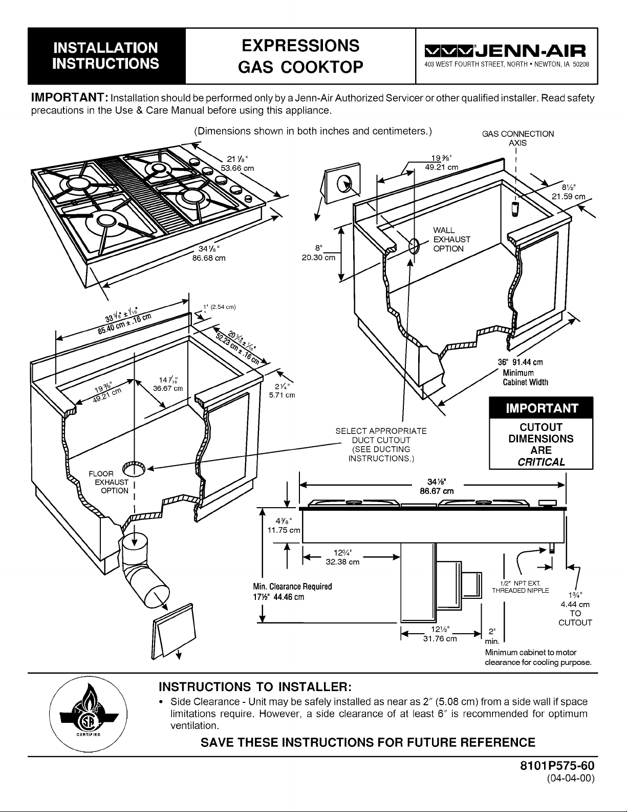
IMPORTANT: Installation should be performed only by a Jenn-Air Authorized Servicer or other qualified installer. Read safety
precautions in the Use & Care Manual before using this appliance.
FLOOR
EXHAUST I
OPTION
(Dimensions shown in both inches and centimeters.)
GAS CONNECTION
AXIS
I
I
I
36"91.44cm
Minimum
CabinetWidth
5.71 cm
SELECT APPROPRIATE
DUCT CUTOUT
(SEE DUCTING
INSTRUCTIONS.)
CUTOUT
DIMENSIONS
ARE
CRITICAL
I
I
i
12%"
32.38 cm
Min.ClearanceRequired
17½"44.46cm
_'_31 76 cm
1
1/2" NPT EXT
THREADED NIPPLE
2"
mln.
Minimum cabinet to motor
clearance for cooling purpose.
1%"
4.44 cm
TO
CUTOUT
INSTRUCTIONS TO INSTALLER:
• Side Clearance - Unit may be safely installed as near as 2" (5.08 cm) from a side wall if space
limitations require. However, a side clearance of at least 6" is recommended for optimum
ventilation.
SAVE THESE INSTRUCTIONS FOR FUTURE REFERENCE
8101 P575-60
(04-04-00)
Page 2

Location Of Your Jenn-Air Appliance
Locate this appliance away from combustible materials such
as window curtains and combustible wall decorations. The
minimum horizontal clearance between the edge of the
appliance and adjacent combustible construction is:
• 0.75 inches (1.90 cm) at rear;
• 2 inches (5.08 cm) at sides
Preparation Of Countertop
The cutout in the countertop into which the appliance is to
be installed should be prepared according to the cutout
dimensions given on page 1 of these instructions.
CAUTION: Cutout dimensions are critical. Dimensions must
be measured and cut accurately to within _+1/16" to ensure
proper fit.
These minimum clearances pertain to vertical surfaces
between the countertop level and a level 18" above the
countertop.
18"
(45.7cm)
Figure 1: Minimum Horizontal Clearance
NOTE: These are not recommended clearances, but rather
the minimum allowable clearances. Overall performance of
your cooktop will be enhanced by providing a 6" or greater
clearance on either side of the unit.
Installing Cabinetry Over Your Cooktop
Observe the following clearances
to overhead cabinetry.
t p-.-,
A
Figure 2
Minimum Clearances to
Overhead Cabinetry
A _
30 inches (76.2 cm) minimum vertical clearance
between cooking surface and combustible
construction or metal cabinets above the appliance.
This clearance may be reduced to not less than 24
inches by protecting the underside of the combustible
material or metal cabinet above the cooking surface
with not less than 1/4-inch insulating millboard
covered with sheet metal not less than O.0122-inch
thick.*
I
Important Installation Suggestions:
1. Chamfer all exposed edges of decorative countertop
laminate to prevent damage from chipping.
2. Slightly radius corners of cutout and file to insure smooth
edges and prevent corner cracking.
3. Rough edges, inside corners which have not been
rounded and forced fits can contribute to cracking of the
countertop laminate.
4. Unit must be supported on all four sides by the
countertop and countertop must be supported within 3" of
edge of cutout.
WARNING
THISPRODUCTSHOULDNOT
BEINSTALLEDBELOWA
VENTILATIONTYPEHOOD
SYSTEMTHATDIRECTSAIR
INA DOWNWARDDIRECTION.
(SEEFIGURE)
THESESYSTEMSMAYCAUSE
IGNITIONANDCOMBUSTION
PROBLEMSWITHTHE GAS
BURNERSRESULTINGIN
PERSONALINJURYANDMAY
AFFECTTHECOOKING
PERFORMANCEOFTHE UNIT.
ART # 9215-252
NOTE:THEFIGUREMAYNOTACCURATELYREPRESENTYOUR
RANGEORCOOKTOP;HOWEVER,THISWARNINGAPPLIESTO
ALLGASCOOKINGPRODUCTS.
B = 13 inches (33.0) maximum depth of cabinets installed
above cooking surface.
CAUTION: Avoid use of cabinets above cooktop for storage
to eliminate potential hazard of reaching over open flames.
*Jenn-Air Over-the-Range microwave ovens (model #M418 and M438) have been listed by UL for use over Gas and Electric Ranges. When properly
installed at a minimum height of 66 inches from the floor tothe top of the microwave, the clearance to the cooking surface at the center will be 13-3/4 inches.
Page 3
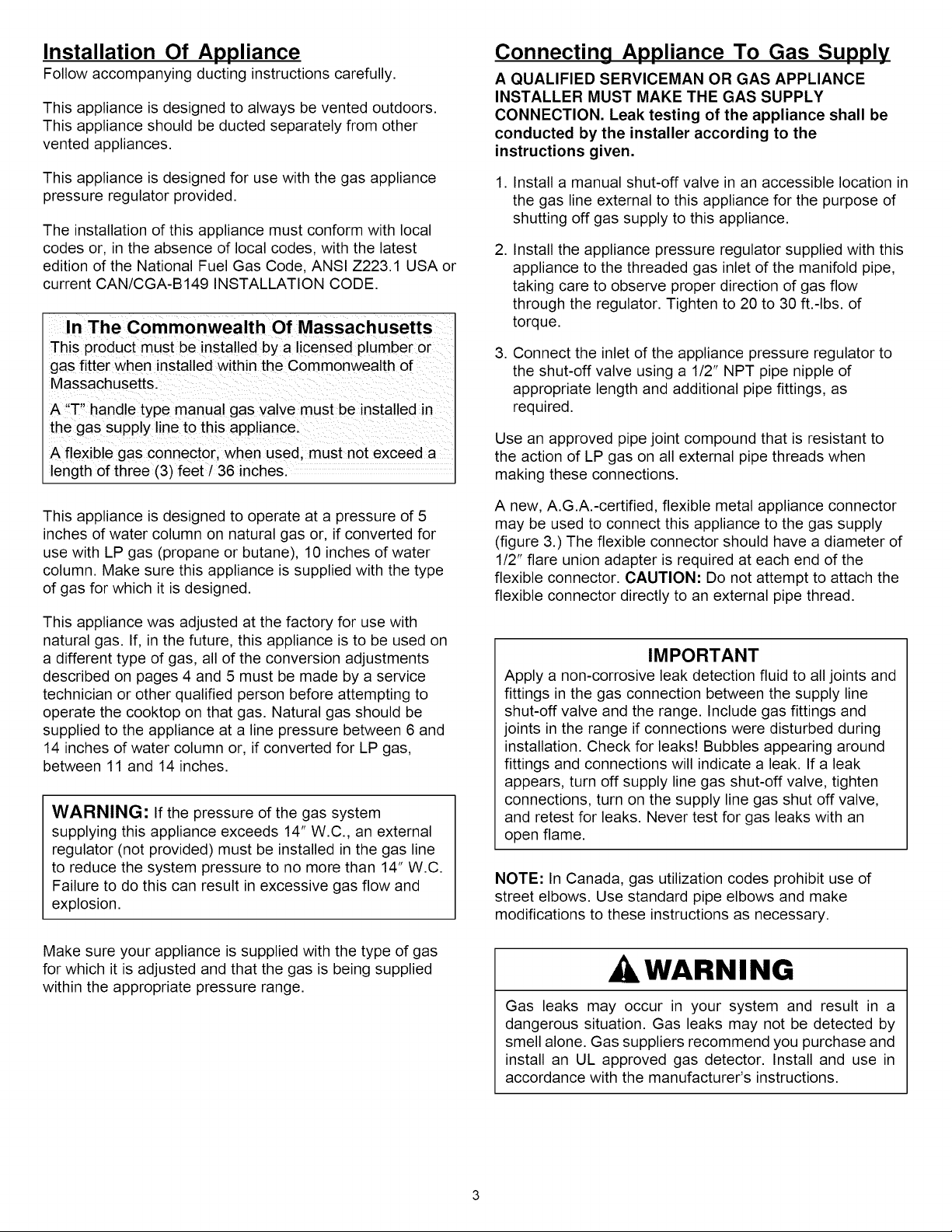
Installation Of Appliance
Follow accompanying ducting instructions carefully.
This appliance is designed to always be vented outdoors.
This appliance should be ducted separately from other
vented appliances.
This appliance is designed for use with the gas appliance
pressure regulator provided.
The installation of this appliance must conform with local
codes or, in the absence of local codes, with the latest
edition of the National Fuel Gas Code, ANSI Z223.1 USA or
current CAN/CGA-B149 INSTALLATION CODE.
In The Commonwealth Of Massachusetts
This product must be installed by a licensed plumber or
gas fitter when installed within the Commonwealth of
Massachusetts.
A "T" handle type manual gas valve must be installed in
the gas supply line to this appliance.
A flexible gas connector, when used, must not exceed a
length of three (3) feet / 36 inches.
Connecting Appliance To Gas Supply
A QUALIFIED SERVICEMAN OR GAS APPLIANCE
INSTALLER MUST MAKE THE GAS SUPPLY
CONNECTION. Leak testing of the appliance shall be
conducted by the installer according to the
instructions given.
1. Install a manual shut-off valve in an accessible location in
the gas line external to this appliance for the purpose of
shutting off gas supply to this appliance.
2. Install the appliance pressure regulator supplied with this
appliance to the threaded gas inlet of the manifold pipe,
taking care to observe proper direction of gas flow
through the regulator. Tighten to 20 to 30 ft.-Ibs, of
torque.
3. Connect the inlet of the appliance pressure regulator to
the shut-off valve using a 112"NPT pipe nipple of
appropriate length and additional pipe fittings, as
required.
Use an approved pipe joint compound that is resistant to
the action of LP gas on all external pipe threads when
making these connections.
This appliance is designed to operate at a pressure of 5
inches of water column on natural gas or, if converted for
use with LP gas (propane or butane), 10 inches of water
column. Make sure this appliance is supplied with the type
of gas for which it is designed.
This appliance was adjusted at the factory for use with
natural gas. If, in the future, this appliance is to be used on
a different type of gas, all of the conversion adjustments
described on pages 4 and 5 must be made by a service
technician or other qualified person before attempting to
operate the cooktop on that gas. Natural gas should be
supplied to the appliance at a line pressure between 6 and
14 inches of water column or, if converted for LP gas,
between 11 and 14 inches.
WARNING: If the pressure of the gas system
supplying this appliance exceeds 14" W.C., an external
regulator (not provided) must be installed in the gas line
to reduce the system pressure to no more than 14" W.C.
Failure to do this can result in excessive gas flow and
explosion.
Make sure your appliance is supplied with the type of gas
for which it is adjusted and that the gas is being supplied
within the appropriate pressure range.
A new, A.G.A.-certified, flexible metal appliance connector
may be used to connect this appliance to the gas supply
(figure 3.) The flexible connector should have a diameter of
112"flare union adapter is required at each end of the
flexible connector. CAUTION: Do not attempt to attach the
flexible connector directly to an external pipe thread.
IMPORTANT
Apply a non-corrosive leak detection fluid to all joints and
fittings in the gas connection between the supply line
shut-off valve and the range. Include gas fittings and
joints in the range if connections were disturbed during
installation. Check for leaks! Bubbles appearing around
fittings and connections will indicate a leak. If a leak
appears, turn off supply line gas shut-off valve, tighten
connections, turn on the supply line gas shut off valve,
and retest for leaks. Never test for gas leaks with an
open flame.
NOTE: In Canada, gas utilization codes prohibit use of
street elbows. Use standard pipe elbows and make
modifications to these instructions as necessary.
WARNING
Gas leaks may occur in your system and result in a
dangerous situation. Gas leaks may not be detected by
smell alone. Gas suppliers recommend you purchase and
install an UL approved gas detector. Install and use in
accordance with the manufacturer's instructions.
Page 4

Connecting Appliance To Electricity
WARNING
Manifold Pi
Appliance Pressure
Regulator, supplied --- /_ku 21LL
(Observe directionality
of Gas Flow) I
I
Flare Union
Adaptor
Flexible
Appliance
- _ Connector
_ (5 ft. max.)
- lare Union
Adaptor
-_- Gas Shut-Off
Valve
-_--1/2" NPT Pipe
I
,_1/2" NPT Pipe
,_ Gas Shut-Off
Outlet
Motor
Nipple
Valve
-1/2" NPT Pipe
_)
Figure 3: Alternative Gas Connections
Pressure Testing
This appliance must be isolated from the gas supply piping
system by closing its individual manual shutoff valve during
any pressure testing of the gas supply piping system at test
pressures equal to or less than 1/2 PSIG (2.5 k pa).
ELECTRICAL GROUNDING INSTRUCTIONS
This appliance is equipped with a three-pronged grounding
plug for your protection against shock hazard and should be
plugged directly into a properly grounded receptacle.
Do not cut or remove the grounding prong from this plug.
The electrical supply required is 110/120 Volts A.C., 60 Hz,
with 15 amp. circuit protection. This appliance is equipped
with a grounded type power cord. A grounded outlet must
be provided. It is recommended, for convenience, this outlet
be located in the shaded area in figure 4.
User may experience occasional circuit tripping if Ground
Fault Circuit Interrupter (GFCI) outlet or breaker is in use.
it-r.- - _ " _.. .._r _ _,_
I
iiiuiiiiiiiiiiiiiiiiii
iiiiiiiiiiiii20iiiV.iiiiiELECTRiCALiiiiiiiiiiiiiiiiiiiiiiiiiiiiiiii
iiiiiiiiiiii0_iiiMAYiiiRiiiiiiiiiiiiiiiiiiiiiiiiiiiiiiiiiiiiiiiiiiiiiiiiiiiiii
iiiiiiiiiiiiLOCAllEDi__iiiiiiii
iiiiiiiiiiiMiiiS_iiiAR_iiiiiiiiiiiiiiiiiiiiiiiiiiiiiiiiiiiiiiiii=
Figure 4: Recommended Location of Electrical Outlet
This appliance, as well as its individual shutoff valve, must
be disconnected from the gas supply piping system during
any pressure testing of the system at test pressures in
excess of 1/2 PSIG (3.5 k Pa).
When checking for proper function of the appliance
pressure regulator, make certain pressure of natural gas
supply is between 6 and 14 inches of water column or, if
converted for LP gas, between 11 and 14 inches.
This appliance, when installed, must be electrically
grounded in accordance with local codes or, in the absence
of local codes, with the latest edition of the National
Electrical Code ANSI/NFPA No. 70 USA or current CSA
STANDARD C22.1 Canadian Electrical Code, part 1.
Page 5

Converting Appliance For Use
With LP Gas
WARNING
Propane conversion is to be performed by a JENN-AIR
AUTHORIZED SERVICER (or other qualified agency) in
accordance with the manufacturer's instructions and all
codes and requirements of the authority having jurisdiction.
Failure to follow instructions could result in serious injury or
property damage. The qualified agency performing this
work assumes responsibility for this conversion.
WARNING
Electrical power and gas must be turned off
prior to conversion.
ALUMINUM VENTUR_ _5/16#NUT DRIVER
BURNER BASE q _ /f / TAPE STUCK TO END
f r • PIECE OF MASKING
IVER
5
ART #9219-g8_-0
ORIFICE SPUD
This appliance was adjusted at the factory for use with
natural gas. To convert it for use with LP gas (propane or
butane), both of the following modifications must be
performed:
A. Replace all orifice spuds
Step 1: Remove the grates and burner heads.
Step 2:
Step 3:
Step 4: Firmly press the nut driver over the orifice
Step 5: Locate the LP orifice spud packet taped to the
Remove aluminum venturi tube.
Trim a small piece of masking tape to the size
of a dime and affix it over the end of a 5/16"
nut driver.
spud (figure 5) and loosen spud by turning
counterclockwise. Carefully lift nut driver out of
burner throat. Orifice spud should be captured
in the recess. Repeat this step for each
burner.
underside of the burner box. The spuds have
small numbers stamped on the side. This
number codes the orifice diameter and its
correct burner location. Reference figure 6 on
the next page for correct LP orifice spud
location for 4 burner and 5 burner models,
respectively.
Figure 5: Removal of Orifice Spud
Step 6:
Step 7:
Step 8:
Step 9:
With the masking tape still in place in the
recess of the nut driver, press an LP orifice
spud into the recess so that it is snugly
captured.
Carefully install the orifice spud in the
appropriate burner throat by turning clockwise
to tighten. Tighten to a torque of 15 to 20
inch-lbs.
Replace cylindrical aluminum venturi tubes.
Replace burner heads and grates. Index each
grate to its burner pan.
Save the orifices removed from the appliance
for future use.
High Altitude Notice
The specified gas burner ratings typically apply to
elevations up to 2000 feet. For higher altitudes, the rates
may need to be reduced to achieve satisfactory operation.
A local certified gas servicer will be able to advise if a
reduction is necessary.
Page 6

Installation of LP Orifice Spuds
Q
Q
Q
Q
@
With a quarter, engage slot and rotate cap 1/8 of a turn
counterclockwise. To remove cap, turn cap over and
reinstall.
@@
Natural Setting LP Setting
Figure 8: Conversion of Harper- Wyman
Appliance Pressure Regulator
Figure 6
B,
Invert Cap in Appliance Pressure Regulator
(See figures 7 and 8.) With the appliance installed, the
regulator is located on the underside of the burner box
on the right hand side at the inlet to the gas manifold.
Identify the make of appliance regulator on the unit and
follow the instructions in the appropriate illustration.
APPLYDOWNWARD
FINGERPRESSURE
ATDISCEDGESTO
CONVERTE APPLYSIDEWARD v_w
_ GAP I ,_. FINGERPRESSURE
_"AND PIN . J fJ_i_m- TOREMOVEPIN
NAT I ._" NAT I LP
i_ "--f - --I I !
R_LP REPLACEPININCAP.
tt
/I @ FROMCAP
After conversion, steps A and B have been completed,
check the appearance of each burners' flame at the Hi and
Lo settings against figure 9. If the flames appear too large
or too small, review all steps to make sure they were
completed correctly.
5 6 7 8 _llooo_ooooil=_)
4 9
,k 17"'_"
off
5 6 7 8
3
Figure 9: Flame Appearance at Hi and Lo
Figure 7: Conversion of Maxitrol
Appliance Pressure Regulator
Page 7

To Convert Appliance For Use With
Natural Gas
If this appliance has been converted for use with LP gas,
each of the following modifications must be performed to
convert the unit back to natural gas.
A. Replace all orifice spuds
Perform Steps 1 through 4 on page 4.
For Step 5: Locate the colored brass natural gas orifice
spuds that were originally installed in this appliance
before its conversion for use with LP gas. Observe the
color of each of the spuds and note the correct burner
location for each spud as shown in figure 10.
Complete Steps 6 through 9 on page 5 to complete the
installation of natural gas main spuds in their correct
locations.
Save the orifices removed from the appliance for future
use. They will be needed if this appliance is again
converted for use with LP gas.
Installation of Natural Gas Orifice
Spuds
Installation of Natural Gas Orifice
Spuds
This appliance is equipped for electronic auto-reignition by
means of a spark igniter located at the side of each burner.
The burners are designed to light at any valve rotation that
admits sufficient gas flow to support a flame and to
automatically re-light following a momentary loss of flame
due to a draft or other adverse condition. This feature is
provided as a convenience and is not intended as a safety
feature.
This appliance has no air shutters, making adjustment of
primary air unnecessary. The burners are designed to
provide optimum aeration of all gases without air shutters.
When operating properly, burners should produce clearly
defined, even blue flames. If the flames have yellow tips or
are hazy and otherwise appear to have insufficient air,
obtain the services of a qualified service technician.
O
Q
O
O
@
._." \\ I_ I II
Figure 10
B. Invert Appliance Pressure Regulator Cap
With the appliance installed, the regulator is located on
the underside of the appliance at the inlet to the gas
manifold. Identify the type of regulator on the unit and
follow the instructions in the appropriate illustration.
(See figures 7 and 8).
After Steps A and B have been completed, check the
appearance of each burners' flame at the Hi and Lo settings
against figure 9. If the flames appear too large or too small,
review all steps to make sure they were completed
correctly.
NATURAL
GAS
BURNER
Right Front
Right Rear
Left Front
Left Rear
CAUTION: Never cover control knobs or surrounding
control surface with utensils, towels or other objects. Never
obstruct free air passage past the control knobs. The knob
openings have been sized to properly control air entry to the
interior of the appliance during operation.
BURNER RATE
(BTU/HR)
12,000
6,500
6,500
10,500
PROPANE
BURNER RATE
(BTU/HR)
8000
4500
4500
8000
ALL GASES
LO RATE
(BTU/HR)
1,600
800
800
1,600
 Loading...