

Page 1
INSTRUCTIONS
GAS COOK"TOP
EXPRESSIONS I L'WmENN'AIR13035 SHADELAND INDIANAPOLIS, IN 46226-0901J
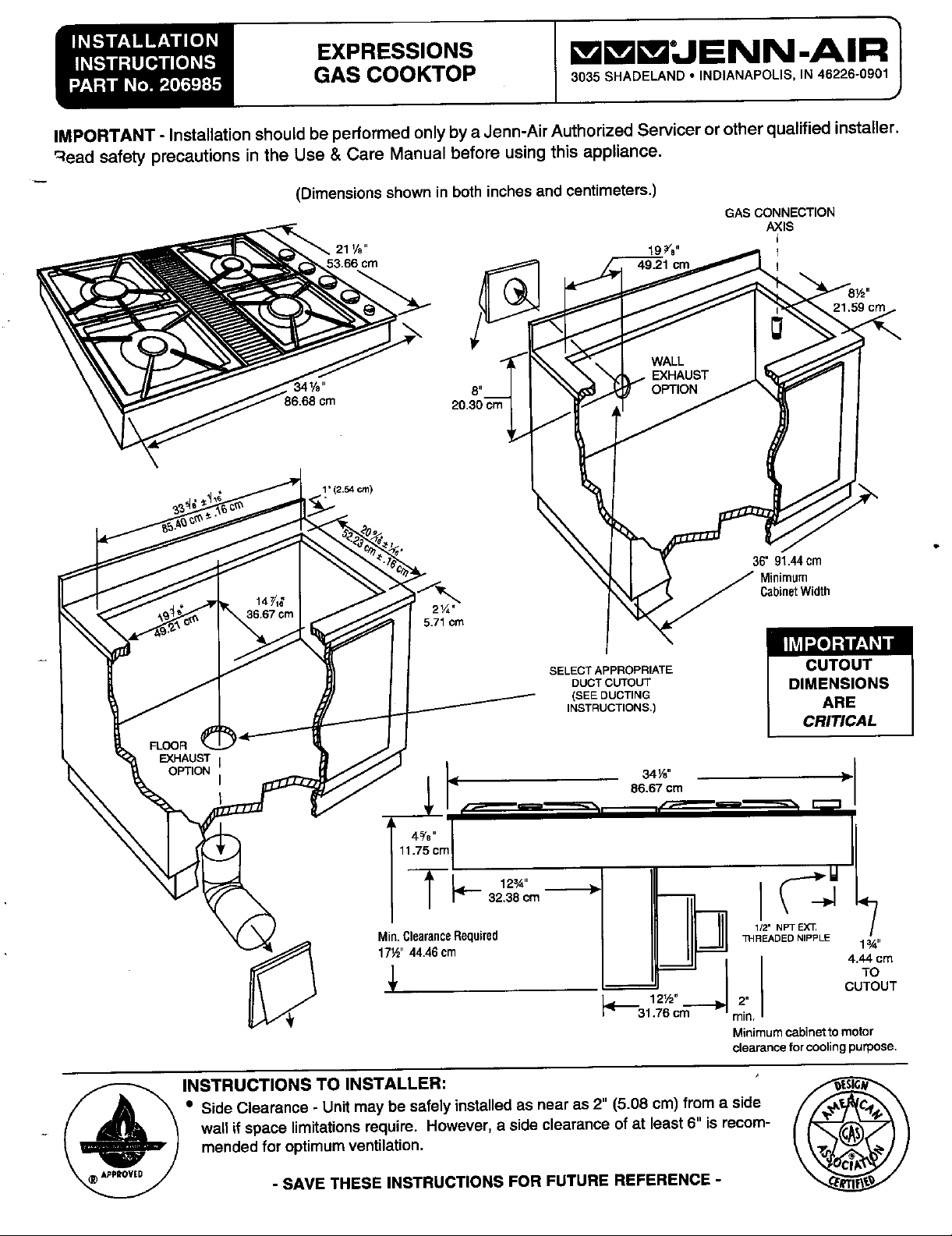
IMPORTANT - Installation should be performed only bya Jenn-Air Authorized Servicer or other qualified installer.
Wead safety precautions in the Use & Care Manual before using this appliance.
(Dimensionsshownin bothinchesandcentimeters.)
GAS CONNECTION
19 _."
49.21 cm !
AXIS
1" 12.54 cm)
36" 91.44 cm
Minimum
CabinetWidth
5.71 cm
IMPORTANT
SELECTAPPROPRIATE CUTOUT
DUCT CUTOUT DIMENSIONS
(SEE DUCTING
INSTRUCTIONS.) ARE
CRITICAL
34_"
86.67 crn
11.75 cm
32.38 crn
_
Clearance
Min½,,44.46 cm 1_"
_ -- TO
. CUTOUT
Required
-- t I 4 °m
I_ 12V2" _, 2"
I_ 31.76 cm rain.
1/2" NPT EX_
_'IREADED NIPPLE
Minimum cabinet to motor
clearance for cooling purpose.
SideClearance- Unitmay besafelyinstalledasnearas 2" (5.08 cm) froma side
wail ifspace limitationsrequire. However,a sideclearanceofat least6" isrecom-
mendedforoptimumventilation.
_ INSTRUCTIONS TO INSTALLER: _lJ
- SAVE THESE INSTRUCTIONS FOR FUTURE REFERENCE - -_cr_-_
Page 2
Location of Your Jenn-Air Appliance Preparation of Countertop
Locate this appliance away from combustible materials such The cutout in the countertop into which the appliance isto be
as window curtains and combustible wall decorations. The installed should be prepared according to the cutout dimen-
minimum horizontalclearance between the edge of the appli- sions given on page 1 of these instructions.
ance and adjacent combustible construction is:
• 0.75 inches (1.90 cm) at rear; CAUTION: Cutout dimensions are critical. Dimensions must
• 2 inches (5.08 cm) at sides be measured and cut accurately to within + 1/16 to ensure
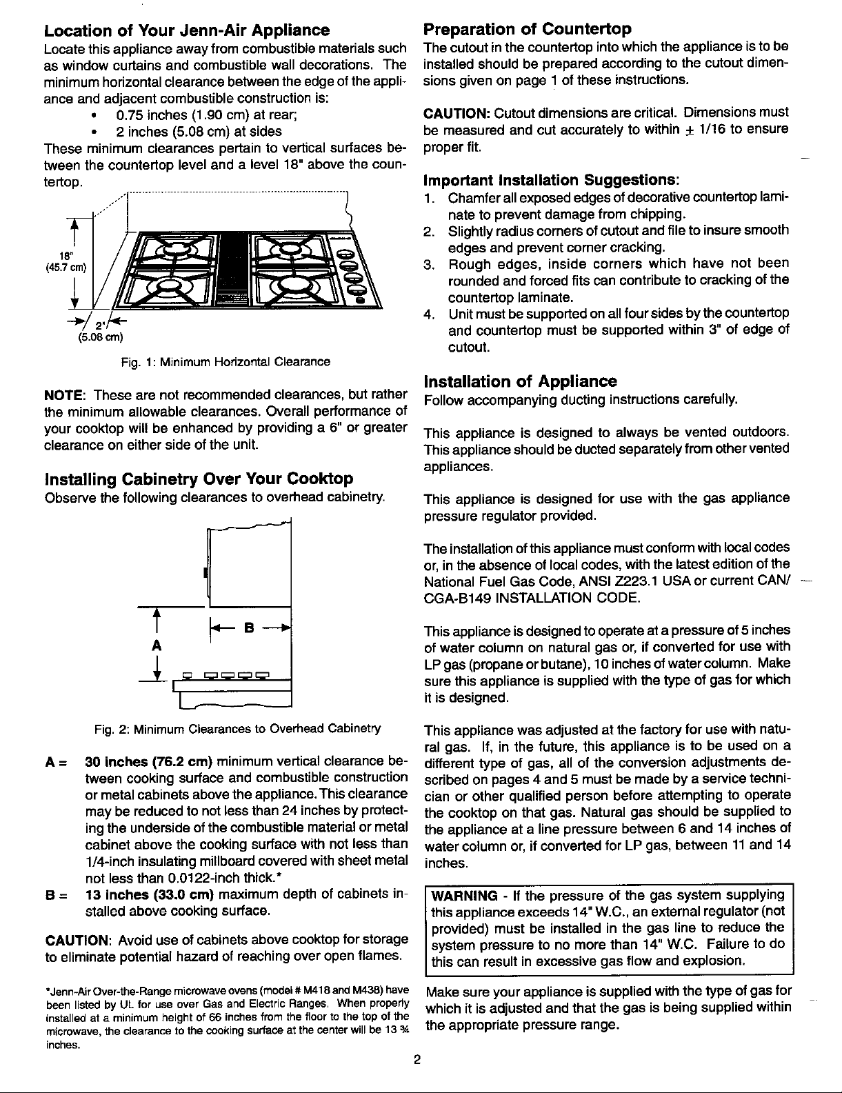
These minimum clearances pertain to vertical surfaces be- proper fit.
tween the countertop level and a level 18" above the coun-
tertop, Important Installation Suggestions:
ff*1
18" edges and prevent corner cracking.
(45.7cm) 3. Rough edges, inside corners which have not been
1. Chamfer allexposed edges of decorative countertop lami-
nate to prevent damage from chipping.
2. Slightly radius corners of cutout and file to insure smooth
rounded and forced fits can contribute to cracking of the
countertop laminate.
_]_J 2./_i_ 4. Unit must be supported on allfour sides by the countertop
(s.o8crn) cutout.
Fig. 1: MinimumHorizontalClearance
and countertop must be supported within 3" of edge of
Installation of Appliance
NOTE: These are not recommended clearances, but rather Follow accompanying ducting instructions carefully.
the minimum allowable clearances. Overall performance of
your cooktop will be enhanced by providing a 6" or greater This appliance is designed to always be vented outdoors.
clearance on either side ofthe unit. Thisappliance should be ducted separately from other vented
appliances.
Installing Cabinetry Over Your Cooktop
Observe the following clearances to overhead cabinetry. This appliance is designed for use with the gas appliance
pressure regulator provided.
The installationof thisappliance mustconform with localcodes
or, in the absence of local codes, with the latest edition of the
National Fuel Gas Code, ANSI 7_223.1USA or current CAN/ --
CGA-B149 INSTALLATION CODE.
'"-f ¢-_ B _ This appliance is designed tooperate at a pressure of5 inches
A of water column on natural gas or, if converted for use with
_, LPgas (propane or butane), 10 inches of water column. Make
I _ _:=E:__;=_ sure this appliance is supplied with the type of gas for which
_ itis designed.
Fig. 2: MinimumClearancesto OverheadCabinetry This appliance was adjusted at the factory for use with natu-
ral gas. If, in the future, this appliance is to be used on a
A = 30 inches (76.2 cm) minimum vertical clearance be- different type of gas, all of the conversion adjustments de-
tween cooking surface and combustible construction scribed on pages 4 and 5 must be made by a service techni-
or metal cabinets above the appliance. This clearance clan or other qualified person before attempting to operate
may be reduced to not less than 24 inches by protect- the cooktop on that gas. Natural gas should be supplied to
ing the underside of the combustible material or metal the appliance at a line pressure between 6 and 14 inches of
cabinet above the cooking surface with not less than water column or, if converted for LP gas, between 11 and 14
1/4-inch insulating millboard covered with sheet metal inches.
not less than 0.0122-inch thick.*
B = 13 inches (33.0 cm) maximum depth of cabinets in- WARNING - If the pressure of the gas system supplying
stalled above cooking surface, this appliance exceeds 14' W.C., an external regulator (not
I provided) must be installed in the gas line to reduce the
CAUTION: Avoid use of cabinets above cooktop for storage system pressure to no more than 14" W.C. Failure to do
to eliminate potential hazard of reaching over open flames, this can result in excessive gas flow and exp os on.
*Jenn-Air Over-the-Range microwaveovens (model # M418andM438) have Make sure your appliance is supplied with the type of gas for
beenlistedby ULfor useover GasandElectricRanges.Whenproperly which it is adjusted and that the gas is being supplied within
installedata minimumheightof66inchesfromthefloortothetopofthe
microwave,theclearancetothe cookingsurfaceatthecenterwillbe 133.4 the appropriate pressure range.
inches.
2
Page 3

Connecting Appliance to Gas Supply Connecting Appliance to Electricity
1. Install a manual shut-off valve in an accessible location WARNING
in the gas line external to this appliance for the purpose
of shutting off gas supply to this appliance. ELECTRICAL GROUNDING INSTRUCTIONS
2. Install the appliance pressure regulator supplied with this This appliance is equipped with a three-pronged ground-
appliance to the threaded gas inlet of the manifold pipe, ingplugfor yourpretection against shockhazard and should
taking care to observe proper direction of gas flow through be plugged directly into a properly grounded receptacle.
the regulator. Tighten to 20 to 30 ft-lbs, of torque. Do not cut or remove the grounding prong from this plug.
3, Connect the inlet of the appliance pressure regulator to The electrical supply required is 110/120 Volts A.C., 60 Hz,
the shut-off valve using a 1/2" NPT pipe nipple of appro- with 15 amp. circuit protection. This appliance is equipped
priate length and additional pipe fittings, as required, witha grounded type power cord. A grounded outlet must be
Use an approved pipe joint compound that is resistant to the provided, It is recommended, for convenience, this outlet be
action of LP gas on all external pipe threads when making located in the shaded area JnFig. 4.
these connections.
I II II I E_
......... ........... =;i
0f GaSRLtW) _
Pre_sun_Regul_0_sapplie_ _ ElSC_ica]0grist
I T0 BI0W_Mot0r 1__Na"o................ "
or =e Fig.4: RecommendedLocationof ElectricalOutlet
Appl_
Co,n_:tor _as.t_
_ _,.,_ v,,_ This appliance, when installed, must be electrically grounded
_ Rrdbls
-_-_n_i_ ANSI/NFPA NO. 70 USA or current CSA STANDARD C22.1
_j_ Pipe
_=_to, Canadian Electrical Code, part 1.
-_'"_ codes, with the latest edition of the National Electrical Code
in accordance with local codes or, in the absence of local
...........................................................
_"_" Pressure Testing
"_IP'PiPe This appliance must be isolated from the gas supplypiping
_' NPT
system by closing its individual manual shutoffvalve during
(a) any pressure testing of the gas supply piping system at test
Fig3: AlternativeGas Connections pressures equal tOor less than 1/2 PSIG (3.5 kPa).
A new, A.G.A.-certlfied, flexible metal appliance connector This appliance, as well as its individual shutoff valve, must
may be used to connect this appliance tothe gas supply (Fig. be disconnected from the gas supply piping system during
3). The flexible connector should have a diameter of 1/2" any pressure testing of the system at test pressures in ex-
and be no more than 5 feet in length. A 1/2" NPT x 1/2" flare cess of 1/2 PSIG (3.5 kPa).
union adapter is required at each end of the flexible connec-
tor. CAUTION: Do not attempt to attach the flexible connec- Whencheckingforproperfunctionoftheappliancepressure
tor directly to an external pipe thread, regulator, make certaJn pressure of natural gas supply is be-
IMPORTANT: Test all connections for gas leaks with a gas, between 11 and 14 inches.
soap and water solution or other accepted leak detection
means. Never test for gas leaks with an open flame.
tween 6 and 14 inches of water column or, ifconverted for LP
"-- NOTE: InCanada, gas utilization codes prohibituse of street
elbows. Use standard pipe elbows and make modifications
to these instructions as necessary.
3
Page 4

Converting Appliance for use with LP Gas
Propane conversionis to be performed by a JENN-AIR
AUTHORIZED SERVICER (or other qualifiedagency) in
WARNING _
accordance with the manufacturer's instructions and all
codes and requirements of the authority having jurisdic-
tion. Failure to follow instructions could result in serious
injuryorpropertydamage. The qualified agencyperform-
ing this work assumes responsibility for this conversion.
WARNING
Electrical power and gas must be turned off prior to con-
version.
This appliancewas adjustedat the factoryfor usewith natu- \\ THISSCREW
ralgas. To convertitfor use withLP gas (propaneor bu-
tane),bothofthe followingmodificationsmustbeperformed: Fig, 6: LocationofLow
LL
._. \ flameadjusting
A. Replace all orifice spuds screwbeneath
Step 1: Removethe gratesand burner heads, r "_ controlpanelglass.
Step2:Withan adjustablewrench,unscrewand removethe
brasscollarnuts.(Fig.5)
Step3: Trima smallpieceof maskingtapetothe size of a Step6: Locatethe LP conversionpacktapedtothesideof
dimeand affixitoverthe end ofa 9/32" nutdriver, the exhaustplenum. Remove the two small bags
Step4: Firmlypressthenutdriveroverthe orificespud(Fig. containingreplacementorifices. Fromthe bag la-
5) and loosen spud by turning counterclockwise, beled Large Burners,removethe two brass simmer
Carefully lift nut driver out of burner throat. Orifice jets marked'38' and insertinthe front-most and rear-
spud should be captured in the recess. Repeat this mostvalves (Fig.7). Turn clockwise until snug. With
step for each burner. Save spuds just removed for masking tape still in place in the recess of the
future use. nutdriver, press a zinc-plated spud marked '99' into -
the recess so that it is captured snugly. Carefully
insertintothethroat of the right front burner. Tighten
to a torque of 15 in-lbs by turning spud clockwise.
BRASS Repeat for the left rear burner using the remaining
COLLAR spudmarked'99' (Fig.7).
NUT _ ' NUT DRIVER
PIECE OF MASKING
TAPE STUCK TO END
OF DRIVER
I -- INDENTATION
ORIFICE SPUD
BURNER BASE _ _ G SimmerSizes
Step5: Removecontrolknobsbypulling With G
a #15Torx driver,remove screw indicatedin Fig.
Fig. 5 RemovalofOrificeSpUdstraightup. __ _ "_"Q
6 from the right-rearand left-front burnervalves. O
Slide control panel glass to the left by 1/8" and
lift glass up and out, exposing the gas manifold
andvalves. Remove thesimmerjets (Fig.6) by Fig.7 InstallationofLP
SimmerJets
turningcounterclockwiseandliftingoutofrecess, andZinc-Placed
Savejets for futureuse. 4 Orifice Spuds.
Page 5

Step 7: From the other orifice bag labeled'Small Burners', Afterconversion,stepsAand B havebeencompleted. Check
remove the two brass simmer jets marked '28' and the appearance of each burners' flame at the Hi and Lo set-
insert in thetwo middle valves (Fig. 7). Turn clock- tings against Fig. 10. If the flames appear too large or too
wiseuntilsnug. Installthe zincplatedspuds marked small, review all steps to make sure they were completed
'74' in the right rear and left front burners using the correctly.
methoddescribed in Step 6. Tighten to a torque of
15 in-lbs.
,Gtep8: Reinstallthe glass controlpanelassemblyand the _ _,=_-- twoTorxscrewsremovedearlier. Replacethe 4_/,-LL_
Step 9: Replacethe brass collar nutsandtighten to atorque
knobs, i0_ °i _ L_ ' _
of 60 in-lbs. Replace burner heads and grates. 0,
Step 10:Affixthe yellow adhesive label from the LP conver-
sion pack tothe exhaust plenum adjacent to the rat-
ing plate.
Step 11:Placethe natural gas simmerjets and brass orifice 5 6 _8
spuds in the plastic bag for future useand reattach 3 _0
bagtosideof plenum. 2 Hi _
il Illl_ L Off
B. Invert cap in appliance pressure regulator
(See Figures7 and8.) Withthe applianceinstalled,the
regulatorislocatedonthe undersideof theburnerbox
on the righthandside at the inlettothe gas manifold. Fig. 10:FlameAppearanceat HiandLo.
Identifythemake of applianceregulatoronthe unitand
followthe instructionsintheappropriateillustration.
APPLVDOWNWAR9TOConvert Appliance for Use with Natural
FINGERPRESSURE
ATDiSCEDGESTO Gas
CONVERTE APPLYSIDEWARO If this appliance has been convertedfor use with LP gas,
-- As CAP _ TOREMOVEPIN
_j LP REPLACEPI(_INCAP.
_,_'AMD PIN , (_ _ FROMCAP convertthe unit back to natural gas.
.AT!jz" .ATT
L.-- , _ , -- A. Replace all orifice spuds
s
_ _ Perform Steps 1through5 on page4.
ig8.- Conversionof Maxitrelappliance spuds with '118' stamped on them are for the left
With a quarter,engageslotand rotatecap 1/8 of a turn rearburner.(Fig.5)
counterclockwise.Toremovecap,turncapover andrein-
stall. Step7: Locatethefour brassnaturalgassimmerjets. In-
,.., FINGERPRESSURE each of the followingmodificationsmust be performedto
LP
I
'_ Step 6: Locatethe four brass natural gas orifice spuds with
small numbers stamped on their sides. The two
pressure
regulator frontandright rearburners. The '166' spud isfor
the rightfront burner. The '156' spudis for the left
Installthejetsmarked'58'inthefront-mostandrear-
mostvalves.(Fig. 6)
CompleteSteps 8 through11 onpage 4 to reassemble
theunit.
B. Invert appliance pressure regulator cap
Withthe appliance installed,the regulatoris locatedon
stallthetwo jetsmarked'43'inthetwo middlevalves.
theundersideoftheapplianceatthe inlettothe gasmani-
the instructionsin the appropriateillustration.(See Fig-
ures8 and9.)
AfterSteps A and B have been completed,checkthe ap-
_ _ fold. Identifythetype ofregulatoronthe unitandfollow
pearanceof each burner'sflame at the Hi and Lo settings
- - NaturalSetting LPSetting againstFig. 10. If theflames appeartoolarge ortoosmall,
reviewallstepsto makesuretheywerecompletedcorrectly.
Fig9: ConversionofHarper-Wyman
appliancepressureregulator 5
Page 6

Burner Ignition and Auto-Reignition
This applianceisequippedfor electronicauto-reignitionby CAUTION: Never cover controlknobs or surroundingcontrol
meansofasparkigniterlocatedatthosideofeach burner, surfacewithutensils,towelsor other objects. Neverobstruct
The burnersaredesignedtolightatanyvalverotationthat free air passage pastthe controlknobs. The knobopenings
admits sufficient gas flow to supporta flame and to auto- have been sized to propedycontrolairentry to the intedoro'
matically re-lightfollowingamomentary lossof flame due the appliance dudngoperation.
to a draft or other adverse condition. Thisfeature is pro-
vided as a convenience and is not intended as a safety
feature.
This appliance has no air shutters,makingadjustmentof
primaryairunnecessary.The burnersaredesignedtopro-
vide optimumaeration of all gases without air shutters.
Whenoperatingpropedy,burnersshouldproduceclearly
defined,evenblueflames. If the flameshaveyellowtips
or are hazyandotherwiseappearto haveinsufficientair,
obtaintheservicesofa qualifiedservicetechnician.
Nat. Gas Propane
Burner Burner All Gases
Rate Rate Lo Rate
Burner (Btu/hr) (Btu/hr) (Btu/hr)
Right Front 12,000 10,500 1,600
Right Rear 6,500 6,500 800
Left Front 6,500 6,500 800
Left Rear 10,500 10,500 1,600
6
 Loading...