

Page 1
JENN-AIR® DETAILED PLANNING DIMENSIONS
A
B
A
A
C
B
H
J
K
I
F
1 of 3
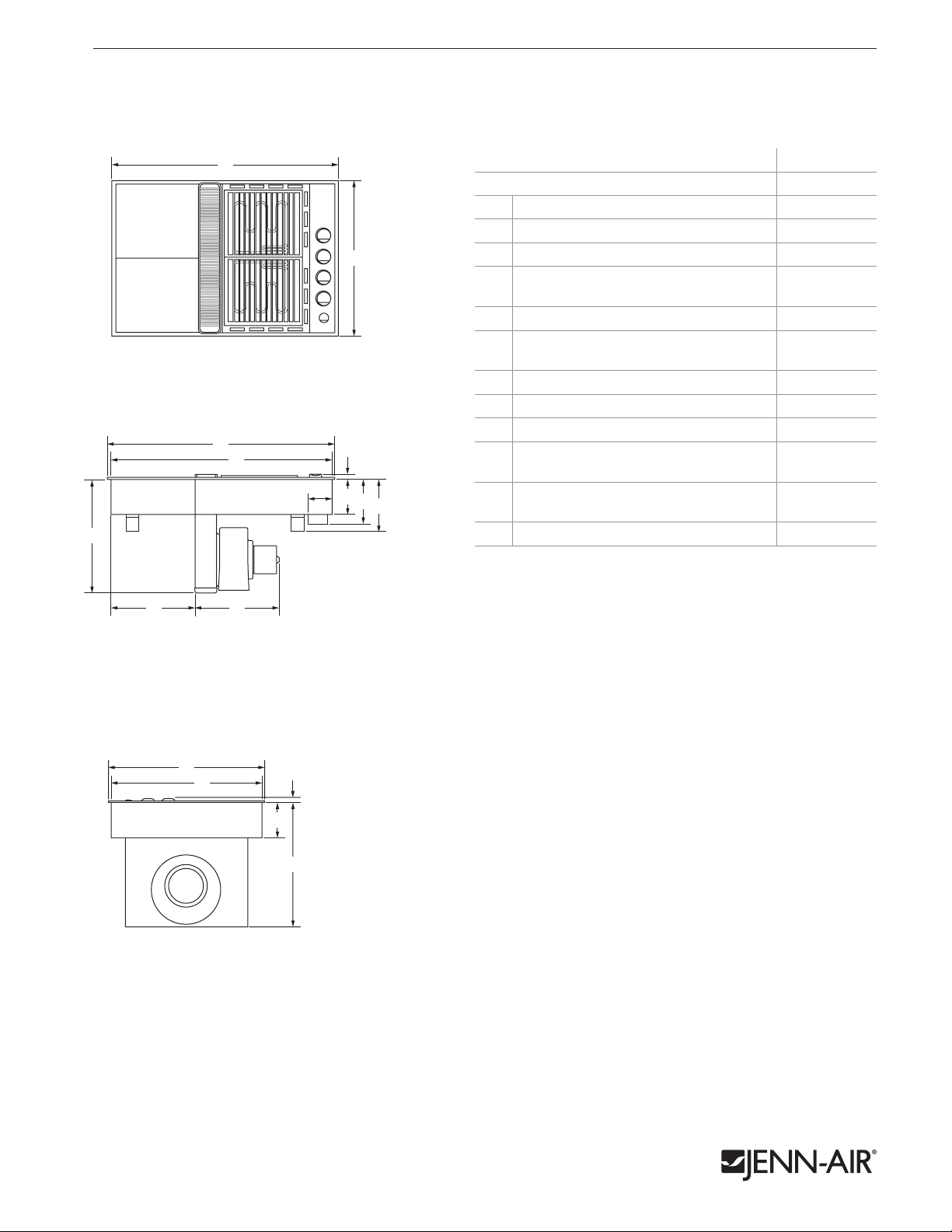
ExPRESSIONS™ cOLLEcTION MODuLAR ELEcTRIc DOwNDRAfT cOOkTOP
CVEX4270 – 31" x 171⁄2" x 211⁄8"
PRODucT DIMENSIONS
A
B
TOp VIEW
A
H
C
F
I
J
K
G
MOdEL # CVEX4270
in cm
Overall width 31 78.6
A
1
Overall depth 21
B
Width of recessed cooktop 30 76.2
C
Width from recessed cooktop
d
to blower motor assembly
Width of blower motor assembly 12
E
Width from electrical housing
F
to recessed cooktop
Height from plenum to countertop 17
G
Height with knobs
H
Height of recessed cooktop 4
I
Height from electrical housing
J
to countertop
Height from grease container
K
to countertop
Depth of recessed cooktop 20
L
⁄8 53.6
1
⁄2 29.1
11
1
⁄2 31.8
3
⁄8 8.5
3
1
⁄2 44.5
3
⁄4 1.8
3
⁄4 12.0
5
⁄8 19.5
7
1
10
⁄4 26.0
1
⁄2 52.0
D E
FRONT VIEW
B
L
H
I
G
SIdE VIEW
Product dimension, cutout and installation specifications are provided for planning purposes only. Before installing
any product, be sure to verify cutout dimensions and electrical/gas connections as actual product dimensions may vary.
JRC120021 03/2012
Page 2
JENN-AIR® DETAILED PLANNING DIMENSIONS
J
BB
K
Side
Cabinet
E*
F
D
e
A
B
B
v
I**
H
v
G
C
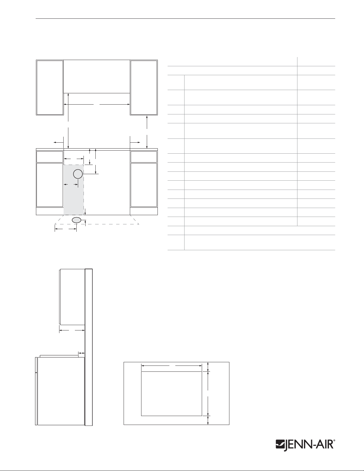
ExPRESSIONS™ cOLLEcTION MODuLAR ELEcTRIc DOwNDRAfT cOOkTOP
CVEX4270 – 31" x 171⁄2" x 211⁄8"
OPENING/cLEARANcE DIMENSIONS
MOdEL # CVEX4270
Width of combustible area above
A
cooking surface (min.)
Width from cooktop to fixed wall
B
or other combustible material (min.)
Width of electrical installation area 11 28.0
C
Width to center of vent opening option 17
d
Height to bottom of uncovered wood or
E*
metal cabinet above cooking surface (min.)
Height to bottom of uncovered wood
F
or metal cabinet (min.)
Height to top edge of electrical installation area 12 30.5
G
Height to center of vent opening option 8 20.3
H
Depth to center of vent opening option 8
I**
Depth of upper cabinet (recommended) 13 33.0
J
Depth from cutout to wall (min.)
K
Width of cutout 30
L
Depth of cutout 20
M
Depth from cutout to front of countertop 2
N
e
Recommended electrical access location
Recommended venting location –
v
see page 3 for ducting information
1
covered by not less than
No. 28 MSG sheet metal, 0.015" (0.4 mm) stainless steel, 0.024" (0.6 mm) aluminum or
0.020" (0.5 mm) copper.
than the cutout.
between the cooktop and side wall for maximum performance.
blower motor and cabinet for proper cooling. A 6" (15.2 cm) clearance
is recommended for servicing access.
of 61⁄4" (15.9 cm) is required.
⁄4" (0.6 cm) ame retardant millboard covered with not less than
L
K
FRONT VIEW
D
E*
D
Side
Cabinet
A
F
G
C
H
v
e
I**
v
* Dimension can be reduced by 6" (15.2 cm) when bottom of wood or metal cabinet is
**Based on installation in a 24" (61.0 cm) base cabinet.
ELECTRICAL REQuIREMENTS
240 volt, 60 Hz, AC only, 40-amp fused, electrical supply is required.
LOCATION REQuIREMENTS
• To ensure cooktop base clearance, cabinet side walls need to be wider
• Grills installed near a side wall must allow a minimum clearance of 6" (15.2 cm)
• A minimum clearance of 2" (5.1 cm) is recommended between the
J
• For removal of the supplied grease container(s), a minimum clearance
K
• An under counter built-in oven cannot be installed under this cooktop.
2 of 3
in cm
31 78.6
1 2.5
3
⁄4 45.1
30 76.2
18 45.7
3
⁄8 21.4
3
⁄4 1.9
1
⁄2 77.3
5
⁄8 52.4
1
⁄8 5.4
SIdE VIEW TOp VIEW – CuTOuT
Product dimension, cutout and installation specifications are provided for planning purposes only. Before installing
any product, be sure to verify cutout dimensions and electrical/gas connections as actual product dimensions may vary.
M
N
JRC120021 03/2012
Page 3

JENN-AIR® DETAILED PLANNING DIMENSIONS
DOwNDRAfT cOOkTOP DucTING ARRANGEMENTS
3 of 3
DucTING cONfIGuRATIONS
Roof jack
(8.3 cm x 25.4 cm) duct –
54' (16.5 m) max.
Transition elbow
REAR duCTING IN WALL TO ROOF
1
3
⁄4" x 10"
DucTING REQuIREMENTS
COOKTOp duCT LENGTH duCT SIzE
10' (3.0 m) or less*
Gas
Between 10' (3.0 m)
and 60' (18.3 m)
10' (3.0 m) or less**
Electric
Between 10' (3.0 m)
and 60' (18.3 m)
*Gas cooktops must use 5" (12.7 cm) diameter for runs of 10' (3.0 m) or less.
** May be used to vent straight out the back of the cooktop and directly
through the wall.
CALCuLATING MAXIMuM duCTING LENGTH
• Maximum ducting length is 60' (18.3 m).
• Each 90° elbow equals 5' (1.5 m) duct.
• Use no more than three 90° elbows.
• Flexible metal vent is not recommended.
• Do not install two elbows together.
NOTES:
• For ducting runs up to 30' (9.1 m), install cooktop as shipped.
• For ducting runs of 31' (9.4 m) to 60' (15.2 cm), remove the
restricter ring on the blower inlet housing.
• For altitudes above 4500' (1272.0 m), reduce recommended
vent run by 20% for best performance.
5" (12.7 cm)
diameter*
6" (15.2 cm)
diameter
1
3
⁄4" x 10"
(8.3 cm x 25.4 cm)
5" (12.7 cm)
diameter**
6" (15.2 cm)
diameter
1
3
⁄4" x 10"
(8.3 cm x 25.4 cm)
REAR duCTING THROuGH WALL TO OuTSIdE
5" (12.7 cm ) to 6" (15.2 cm)
diameter transition
Transition elbow
SIdE duCTING IN TOE KICK TO OuTSIdE
Product dimension, cutout and installation specifications are provided for planning purposes only. Before installing
any product, be sure to verify cutout dimensions and electrical/gas connections as actual product dimensions may vary.
31⁄4" x 10"
(8.3 cm x 25.4 cm) duct
THROuGH FLOOR BETWEEN JOISTS TO OuTSIdE
6" (15.2 cm)
diameter elbow
6" (15.2 cm) diameter duct –
1
⁄2' (15.7 m) max.
51
6" (15.2 cm)
diameter wall cap
JRC120021 03/2012
 Loading...