

Page 1
www.dexpress.com DIMENSION EXPRESS Fax on Demand (775) 833-3600
This Data Sheet Includes Information On
Jenn-Air
• Product Model Number (s): •
Expressions™ Collection Cooktop: C2000
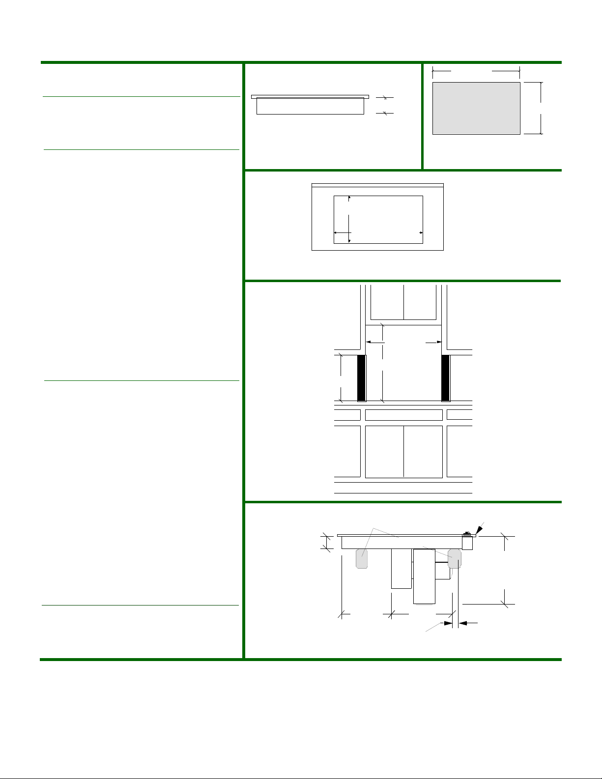
• Dimensions (Actual Size) •
Distance from top of counter to bottom of unit:
Min. spacing from cooktop edge to nearest
vertical combustible wall to the RIGHT:
Min. spacing from cooktop edge to nearest
Min. spacing from cooktop edge to nearest
vertical combustible wall to the REAR:
Minimum spacing to front edge of counter:
Minimum width of cabinet directly above:
Minimum distance between countertop
• Additional Information •
• C2000 is a reference number only. A control-module
package (CP200B [black]) and a base module (CM200)
must be selected to configure C2000. One grill
assembly is included in every control-module
package. This Data Sheet contains specifications for
installing CP200B with CM200.
• IMPORTANT: If you are using Jenn-Air Model Number
AOT30B (2" Double Bay Trim Kit) with this installation
you MUST request its Data Sheet. The cutout sizes are
different when using the trim kit.
• Minimum horizontal clearance between the edge of
the appliance and combustible construction extending
from the cooking surface to 18" above the cooking
surface when next to a grill cartridge is 6". All other
cartridges require 1".
• Minimum width of base cabinet is 30". Some 30"
cabinets may require right side wall notched to provide
required clearance to control panel.
See page 2-3 for additional information
Control Module: CP200B
Base Module: CM200
Overall width:
Overall depth:
Cut-Out width:
Cut-Out depth:
vertical combustible wall to the LEFT:
Minimum distance between cooktop
and cabinet directly above:
Maximum depth of cabinets directly
above and adjacent:
and adjacent cabinet above:
29 7/16"
20 9/16"
29 15/16"
21 1/8"
see below
see below
see below
1"
2 1/8"
30"
30"
13"
18"
Side View (not to scale)
20 9/16"
18"
Grease containers
4 3/4"
Front View
see below
29 7/16"
30"
30"
Base Module
29 15/16"
Overall Dimensions
Top View (not to scale)
Cut-Out Dimensions
Countertop View
(not to scale)
Cabinet Requirements
Wall View
(not to scale)
Minimum horizontal
clearance between the
edge of the appliance
and combustible
construction extending
from the cooking
surface to 18" above
the cooking surface
when next to a grill
cartridge is 6". All other
cartridges require 1".
Control Module
17 1/2"
Minimum
clearance
required
of Cooktop and
Subject to change without notice. This system is designed to
be updated daily if necessary. Dimension Express is not
responsible for use of superseded, voided, or outdated data
sheets. Because of the difficulty or impracticability of determining actual damages, liability of Dimension Express shall
not exceed $50.00.
Copyright © Dimension Express, 2000.
• NEVER reuse Data Sheets. Data Sheets are subject to change without • Call Dimension Express if you have any questions at (775) 833-3633 •
notice. Dimension Express is a FREE service bureau and is updated daily, • Always refer to a current Code at a Glance or manufacturer directory •
it makes far more sense to spend the time necessary to request new Data • Data Sheet codes change on the first of odd numbered months at 12:01am •
Sheets for each project, as opposed to the problems, time, costs, and risks
associated with reusing old Data Sheets.
321
Attached Blower
(not to scale)
12 1/2"11 7/16"
Provide 2" min. cabinet clearance to motor for
cooling purpose. 6" recomended for servicing.
BN151.5 • A321B149C150 • 31469 • 002906 • 135550 • 13105
21 1/8"
Page 2
www.dexpress.com
DIMENSION EXPRESS
Fax on Demand (775) 833-3600
Additional Information:
• Cabinetry over cooktop : 30' minimum clearance between the top of
the cooking surface and the bottom of an unprotected wood or metal
cabinet. 24" minimum when bottom of wood or metal cabinet is
protected by not less than 1/4" flame retardant millboard covered with
not less than no. 28 MSG sheet steel, 0.015" stainless steel, 0.024"
aluminum or copper.
• To eliminate the hazard of reaching over heated surface units,
cabinet storage space located above the surface units should be
avoided. If cabinet storage is to be provided, the hazard can be
reduced by installing a range hood that projects horizontally a
minimum of 5" beyond the bottom of the cabinets.
• Countertop must be supported within 3" of cutout.
• Radius corners of cutout and file to insure smooth edges and prevent
corner cracking (1/8" Radius).
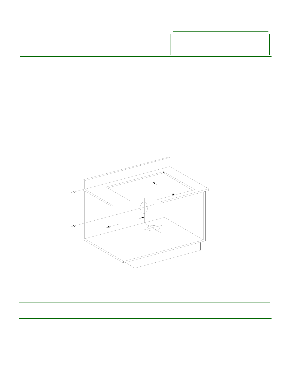
Duct locations
(not to scale)
Page 2
This Data Sheet Includes Information On
Jenn-Air
• Product Model Number (s): •
Expressions™ Collection Cooktop: C2000
Control Module: CP200B
Base Module: CM200
• Blower can be swiveled 90°.
• Electric supply: 120/240 or 120/208 VAC, 60Hz. 40 amp grounded
circuit is required (Load is 35.2Amps @ 120/240VAC) . Power cord is
NOT supplied. 208 volt cartridges must be used when connecting to
120/208 VAC.
• Duct requirements: See page 3 for ducting information and below for
location.
• Under counter access must be provided to remove and empty
grease container(s).
• Accepts Jenn-Air Expression™ Collection Cartridges.
14 7/16"
8"
17 3/4"
Top of counter to centerline of back duct location: 8"
Left edge of cutout to centerline of back and bottom duct locations: 17 3/4"
Front edge of cutout to centerline of bottom duct location: 14 7/16"
Subject to change without notice. This system is designed to be updated daily if necessary. Dimension Express is not responsible for use of superseded, voided, or
outdated data sheets. Because of the difficulty or impracticability of determining actual damages, liability of Dimension Express shall not exceed $50.00.
Copyright © Dimension Express, 2000.
• NEVER reuse Data Sheets. Data Sheets are subject to change without • Call Dimension Express if you have any questions at (775) 833-3633 •
notice. Dimension Express is a FREE service bureau and is updated daily, • Always refer to a current Code at a Glance or manufacturer directory •
it makes far more sense to spend the time necessary to request new Data • Data Sheet codes change on the first of odd numbered months at 12:01am •
Sheets for each project, as opposed to the problems, time, costs, and risks
associated with reusing old Data Sheets.
BN151.5 • A321B149C150 • 31469 • 002906 • 135550 • 13105
149
Page 3

www.dexpress.com
DIMENSION EXPRESS
Fax on Demand (775) 833-3600
Additional Information:
Ducting Installation Guidelines
Page 3
This Data Sheet Includes Information On
Jenn-Air
• Product Model Number (s): •
Expressions™ Collection Cooktop: C2000
Control Module: CP200B
Base Module: CM200
Unit is rated at a maximum of 60 feet of straight duct, 300CFM of
"make-up" is required. The blower has 2 range settings; Low range
is used when equivalent duct length is up to 30 feet and high range
is used when equivalent duct length is between 31 and 60 feet.
1. Use 6" diameter round or 3 1/4" x 10" rectangular only, except
for equivalent duct lengths of 10 feet or less that vent straight out
the back of the cooktop and directly through the wall. Equivalent
duct lengths of 10 feet or less can use 5" round duct. A transition
from 5" round duct is necessary when connecting to 6" round or
3 1/4" x 10" duct.
2. Do not use 5" elbows except in a 5" system. Instead use a 5" to
6" transition followed by a 6" elbow, or a 5" to 3 1/4" x 10" elbow
transition.
3. Use quality metal duct of at least 26 gauge galvanized or 24 gauge
aluminum. Inferior quality pipe fittings can cause up to twice the
restriction and is a poor value. 6" diameter PVC sewer pipe can be
used for under slab installations. Local codes may require a heavier
gauge material or restrict PVC. Check your local codes.
4. Distance between adjacent fittings (elbows, transitions etc.)
should be at least 18". The farther the better. Closer distance
promotes turbulence which reduces airflow.
5. The number of downstream elbows or transitions should be
limited to three. The initial 5" to 6" straight transition, if used, need
not be counted in this number.
6. Handmade crimps are likely to cause restrictions.
7. If an alternate wall or roof cap is used, be certain duct size is not
reduced, and there is a backdraft damper. It is best to use listed caps
to be certain of proper performance.
8. Thermal breaks: In areas of extreme cold weather, it may be
necessary to provide a short length of nonmetallic duct as close to
the wall as possible, to prevent conduction along the metal duct.
9. High altitude installations: It is advisable to reduce allowable duct
run by 20%.
10. In Canada, the installation must conform with local codes.
11. Elbows, wall caps and other fittings are shown below with their
equivalent straight duct length. Each fitting value must be added to
the amount of straight duct length used, to determine overall straight
duct equivalent length (60 feet maximum).
12. When using flexible duct multiply length of flexible duct by 2.
Duct Equivalents
Equivalent
Length
5 feet
5 feet
12 feet
0 feet
0 feet
0 feet
2 feet
Subject to change without notice. This system is designed to be updated daily if necessary. Dimension Express is not responsible for use of superseded, voided, or
outdated data sheets. Because of the difficulty or impracticability of determining actual damages, liability of Dimension Express shall not exceed $50.00.
Copyright © Dimension Express, 2000.
• NEVER reuse Data Sheets. Data Sheets are subject to change without • Call Dimension Express if you have any questions at (775) 833-3633 •
notice. Dimension Express is a FREE service bureau and is updated daily, • Always refer to a current Code at a Glance or manufacturer directory •
it makes far more sense to spend the time necessary to request new Data • Data Sheet codes change on the first of odd numbered months at 12:01am •
Sheets for each project, as opposed to the problems, time, costs, and risks
associated with reusing old Data Sheets.
Duct
Fitting
6"
90° Elbow
3 1/4" x 10"
Elbow
3 1/4" x 10"
Flat Elbow
5" and 6"
Wall Caps
3 1/4" x 10"
Wall Cap
10" x 10"
Roof Jack
5" and 6"
Thermal
Break
Part
Number
5": A405
6": A406
A403
Legh: 5950
JA: 701943
5": 708786
6": 715557
Part
Number
A456
A496
A496
A463
A463
A495
Duct
Fitting
6"
45° Elbow
5" to 6"
Transition
6" to
3 1/4" x 10"
90° Elbow
3 1/4" x 10"
to 6"
90° Elbow
6" to
3 1/4" x 10"
Transition
3 1/4" x 10"
to 6"
Transition
5" to
3 1/4" x 10"
90° Elbow
Equivalent
Length
2 1/2 feet
Air flow this
1 foot
5 feet
9 feet
1 foot
4 1/2 feet
6 feet
BN151.5 • A321B149C150 • 31469 • 002906 • 135550 • 13105
direction NOT
recommended
Air flow this
direction NOT
recommended
Air Flow
Air Flow
Air Flow
Air Flow
Air Flow
Air Flow
150
 Loading...