

Page 1
JEFF ROWLAND
DESIGN GROUP
Page 2

Model 8T/Ti
Stereo Power Amplifier
Owner’s Manual
Page 3

Introduction
W
elcome to the Jeff Rowland Design Group “family” and congratulations on your purchase of what is unquestionably
one of the world’s finest audio power amplifiers.
þ With its combination of features such as numerous function control
and interconnection possibilities, precision electronic circuitry and accurately machined chassis components throughout,
your Model 8T/Ti Amplifier will offer you many years of musically satisfying enjoyment.
þ Please take a few moments to
read the remainder of this Owner’s Manual. A thorough understanding of the operational features will allow you to gain
the maximum performance and ease of use for which this Amplifier was designed.
þ Please note that your Model 8T/Ti
Stereo Amplifier serial number begins with the letter A. This number is recorded below and is also located on the rear
panel of the chassis. Please include this number with any correspondence regarding your Model 8T/Ti Amplifier.
þ It has
been my joy to create an audio component of enduring value which will reflect a higher ideal of musical and artistic
expression. It is my hope that these qualities will enrich your experience of ownership.
Enjoy the music!
Jeff Rowland
President
þ Jeff Rowland Design Group, Inc.
2911 North Prospect Street
Colorado Springs, CO 80907
Phone: 719/473-1181
Fax: 719/633-4158
Page 4

Product Features
þ XLR Balanced Input jacks for balanced (Differential Mode™) system
configurations
þ RCA Input jacks for unbalanced (single-ended) system configurations
þ Two parallel connected speaker output connectors for both right and
left channels
þ User-selectable overall gain of 26 or 32 dB
þ User-selectable input impedance of 36k or 600 ohms for both balanced
and unbalanced inputs.
þ User-selectable absolute phase on balanced input
þ User-selectable input muting
þ User-selectable switching between balanced and unbalanced inputs
þ Front panel standby/power button illumination can be turned off
during listening
þ Optional remote (wired or wireless) power ON/OFF switching
þ Automatic temperature stabilizing circuitry maintains constant
operating temperature
þ Standby power condition reduces warm-up time
þ Fail-safe operation provided by user-resetable AC and DC magnetic
circuit breakers located on rear panel
þ Quiet, transient-free operation during power and function
mode switching
þ Automatic input muting under anomalous input or output operating
conditions
þ Balanced Differential Mode™ circuit topology implemented from input
to output
þ Plug-in modules, containing critical electronic circuitry, enhance
thermal stability, mechanical integrity and serviceability
þ Low-resonance, structurally integrated chassis of precision machined
aluminum alloy components
Introduction / Product Features
Page 5
1
2
3
4
5
Contents
Page 6

Initial Inspection
I
nspect the shipping container for damage. If the shipping container,
packing material, amplifier or accessories are damaged or missing, notify
your dealer and the shipper (if a claim is to be made). Note: Many shippers
require notification and an inspection within twenty-four (24) hours of
delivery to ascertain the nature of damages incurred.
Your Model 8T/Ti Amplifier has undergone extensive performance
evaluations, listening tests, quality control inspections and a minimum
seventy-two (72) hour burn-in period prior to shipment and should be in a
perfect operational condition upon receipt. If the Amplifier does not operate
correctly, please notify your dealer immediately.
We strongly suggest that you save all packing materials. If the Amplifier is
returned to your dealer or Jeff Rowland Design Group, the original packing
materials must be used for shipment. Neither Jeff Rowland Design Group
nor the shipper can be held responsible for damages incurred during transit
if the original factory packing is not used. All factory returns require that a
Return Authorization number be issued by Jeff Rowland Design Group prior
to shipment.
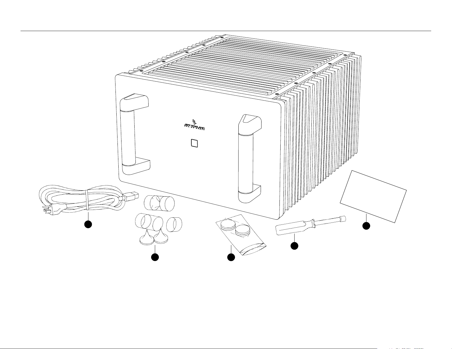
Contents
E
nsure that all of the auxiliary components listed below are enclosed
within the accessory box. Refer to the diagrams illustrated above and verify
the components included.
1 AC power cable
2 Four (4) spiked coupling interface supports
3 Four (4) compliant isolation interface supports
4 One (1) speaker terminal hand wrench (7/16 inch)
5 One (1) warranty card (in some countries warranties are provided by
the respective importer)
Initial Inspection / Contents
Page 7
Front & Rear Panel Function Controls
A
6
3
2
5
1
4
Page 8

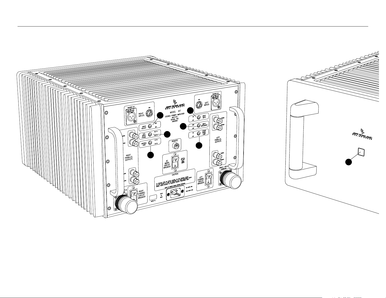
Front & Rear Panel Function Controls
Before attempting any system interconnection, please familiarize yourself
with the front and rear panel controls of the Model 8T/Ti Amplifier. The
descriptions below refer to the numbers and letters associated with the
features in the diagram above.
Front Panel
A
FRONT PANEL STANDBY/POWER button: Press to operate
Amplifier. Press again to place Amplifier in standby mode. This button
will illuminate when the Amplifier is operational. When the button is
not illuminated, all Amplifier inputs are muted and internal circuitry is
reverted to power-saving (standby) mode. Note: All ON/OFF power
switching should be initiated ONLY with this button. Anomalous
operating conditions will automatically switch the Amplifier off (no
illumination) and will prevent the Amplifier from being switched back
on again until such a condition is eliminated.
Rear Panel
(Note: All of the switches described below can be switched, if desired, while
the Amplifier is operational and playing music.)
1 INPUT SELECT switch: This switch selects either the RCA single-
ended inputs or the XLR balanced inputs. Note: When the RCA position
is selected, pin 2 of the XLR input is shorted to pin 1.
2 XLR INPUT PHASE switch: This switch selects between two XLR
connector standards in use worldwide. The XLR standard of associated
equipment should be noted and matched with the Model 8T/Ti to
achieve correct absolute phase. The Amplifier is non-inverting with
respect to XLR Pin 3 when the switch is in the upper position.
Furthermore, the Amplifier is non-inverting with respect to XLR Pin 2
when the switch is in the lower position. Regardless of the standard
selected, this switch can be used to conveniently reverse the absolute
phase of the entire audio system when XLR balanced inputs are used.
Note: The XLR standard used worldwide assigns Pin 1 to ground or input
interconnect shield potential.
3 OVERALL GAIN switch: This switch selects between a high (32 dB) or
normal (26 dB) overall gain structure of the Amplifier.
4 INPUT MUTE switch: This switch removes the internal input signal
connection from the Amplifier input circuitry thus permitting input
interconnect cables to be removed or inserted safely without switching
the Amplifier off.
5 INPUT IMPEDANCE switch: This switch selects between a high
(36k) or low (600 ohm) input impedance at the balanced XLR input
jacks or unbalanced RCA jacks.
6 FRONT PANEL LAMP switch: When placed in the OFF position, this
switch will cease front panel illumination during listening. Front panel
indication of operational status is restored when the switch is returned
to the ON position.
Front & Rear Panel Function Controls
Page 9
2
4
4
1
1
3
Rear Panel Power Connections
Page 10

Installation
L
ocate the Amplifier as close as possible to its final installation point. Allow
access to the rear panel for making connections.
The Model 8T/Ti Amplifier is convection cooled, eliminating the need for
fan or forced air cooling. When operating, the chassis should have at least
two (2) inches of air space around the heatsink areas. Multiple chassis can
be stacked vertically thus facilitating an upward flow of warm air currents
throughout the vertical heatsink fin areas. This upward flow must not be
impeded or recirculated around the chassis if proper cooling is to be
maintained.
Supplied with your Model 8T/Ti Amplifier are two different support systems.
An assessment of the supporting structure should be made to determine the
proper system for the Amplifier. Both spiked and compliant interface
supports can be easily installed within the indentations on each of the four
chassis pods located underneath the corners of the chassis. These system
options permit the coupling or decoupling of the Amplifier chassis to the
supporting structure.
As a general rule, most installations allow the Amplifier chassis to be rigidly
coupled to the supporting structure via the spiked coupling interface
supports. In carpeted installations, these supports provide excellent coupling
from the Amplifier chassis to the rigid supporting structure below. In
installations where the integrity of the supporting structure is poor, the
Amplifier chassis can be loosely coupled to the supporting structure via the
compliant isolation interface supports. This will help attenuate the transfer
of spurious energy from the supporting structure into the Amplifier chassis.
Note: Another installation option, when incorporating the Battery Power
Supply, utilizes its chassis as a stable, high mass structural support for the
Amplifier chassis. In this configuration, the Battery Power Supply chassis is
rigidly coupled to the supporting structure via the spiked coupling interface
supports and the Amplifier is placed directly above the Battery Power
Supply and isolated via the compliant isolation interface supports.
If desired, a coin may be placed directly under the point of the spiked
coupling support to prevent damage to various surfaces (i.e. hardwood
floors).
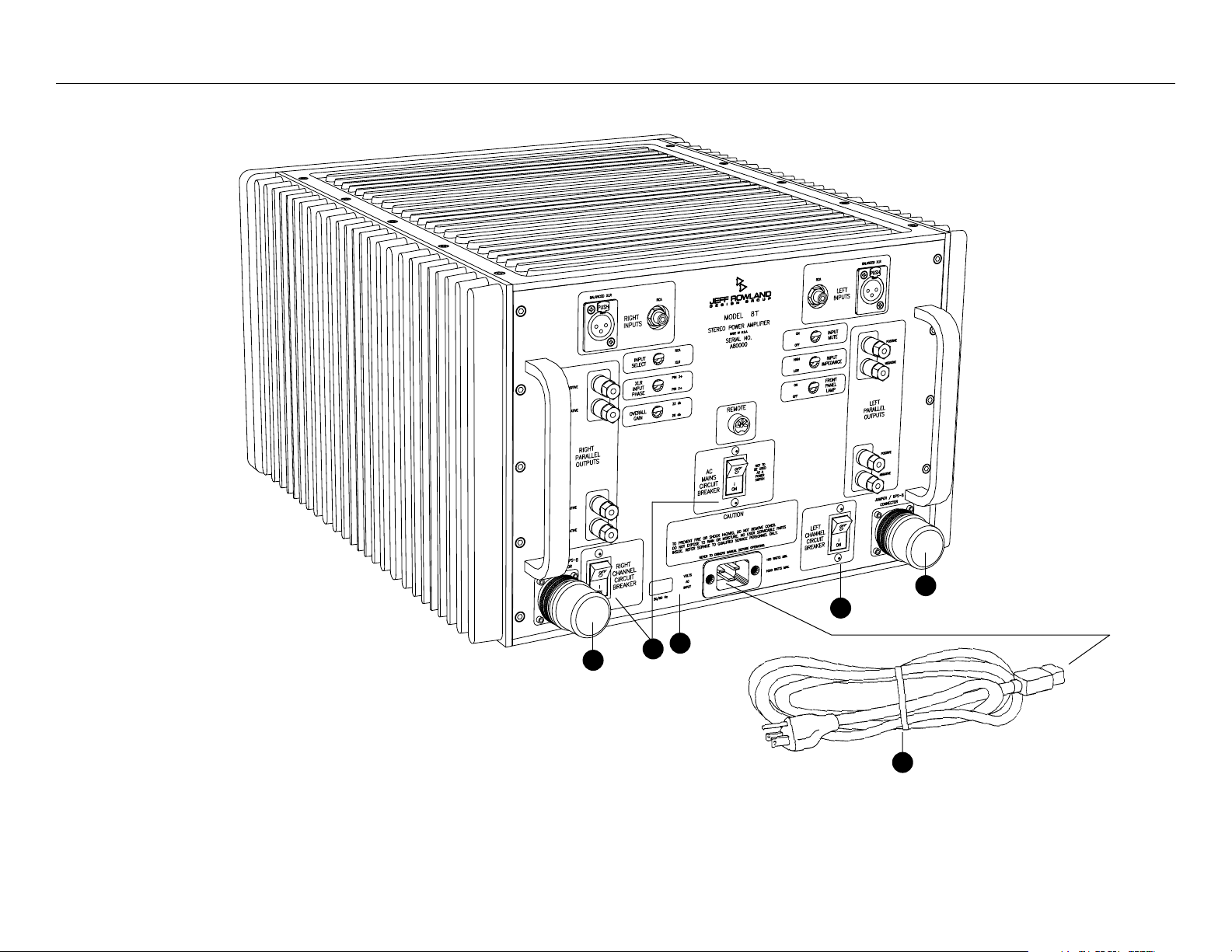
Rear Panel Power Connections
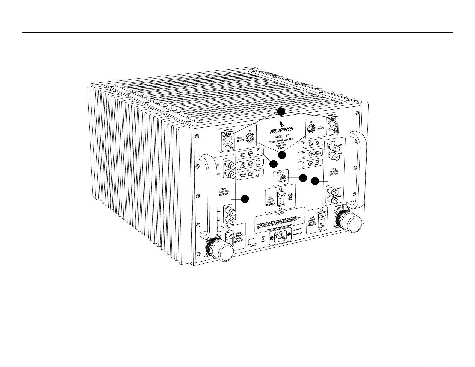
Important: Please strictly follow the steps in order as outlined below
before operating your Model 8T/Ti Amplifier.
1 Verify that the AC MAINS CIRCUIT BREAKER and both RIGHT and
LEFT CHANNEL CIRCUIT BREAKERS are in the ON position (green
color visible).
2 Verify that the VOLTS AC INPUT identified on the rear panel
corresponds to the AC mains voltage of your service area.
3 Install the AC power cable between the Amplifier and an active AC
mains outlet.
4 Power Supply Jumpers. Do not remove unless used with the optional
BPS-8 Battery Power Supply. If removing, always use the knurled ring
to loosen and remove these jumpers and covers as one unit.
Note: If the Amplifier is moved to another location, simply disconnect the
AC power cable from the AC mains wall outlet. It is not recommended to
use the AC MAINS CIRCUIT BREAKER to remove or connect AC mains
power to the Amplifier.
Installation / Rear Panel Power Connections
Page 11
2
1
3
4
4
5
Signal Connections
Page 12

Signal Connections
T
he Model 8T/Ti Amplifier offers unprecedented compatibility with
associated audio components. When connecting or disconnecting speaker
or interconnect cables, it is only necessary that the INPUT MUTE switch be
in the ON position if the Amplifier is already in operational mode.
1 Position INPUT SELECT switch to XLR if you are using XLR balanced
interconnects or to RCA if you are using RCA unbalanced
interconnects from your preamplifier or other source component.
2 Select one input — either BALANCED XLR INPUTS or UNBALANCED
RCA INPUTS — on each channel to match your interconnect cable
used.
3 A slight click may be heard when the XLR interconnect plugs are
installed correctly and latched. The latch (located on the input
connector and labeled PUSH) must be pressed to remove the XLR
interconnect cable.
4 Unscrew one set of the PARALLEL OUTPUTS connectors on each
channel and install the positive and negative loudspeaker cable spade
terminals to the respective Amplifier PARALLEL OUTPUTS. Red is
normally positive; black is normally negative. Since both upper and
lower PARALLEL OUTPUTS are electrically identical, the extra set can be
used in loudspeaker bi-wire configurations. ALWAYS USE THE
SUPPLIED SPEAKER TERMINAL HAND WRENCH WHEN CONNECTING
OR DISCONNECTING LOUDSPEAKER CABLES. DO NOT
OVERTIGHTEN THESE TERMINALS.
WARNING: Both positive and negative PARALLEL OUTPUTS
are electrically active with respect to chassis and/or system ground potential.
It is important that both of these outputs are electrically isolated from system
ground potential. This precludes the use of this Amplifier in certain loudspeaker switching configurations (sometimes used in retail demonstrations)
and testing or servicing situations where either positive or negative outputs
can be connected to ground potentials. Failure to observe these precautions
may result in damage to the Amplifier and may void your warranty. Consult
the factory first if the Amplifier is to be used under these conditions.
Remote
5
A REMOTE connector (DIN 5-pin) is provided on the rear panel for
remotely switching the Amplifier between operational and standby
modes. The pin connections on this connector parallel the electrical
contacts of the FRONT PANEL STANDBY/POWER button and lamp. An
optional wired remote switch or infrared wireless remote sensor can be
plugged into the REMOTE connector to facilitate this function. Contact
your dealer or Jeff Rowland Design Group for further information and
availability of this feature.
Signal Connections
!
Page 13

Operation
A
fter following the procedures outlined in the Installation/Rear Panel
Power Connections and Signal Connections sections, the Amplifier can be
turned on by pressing the FRONT PANEL STANDBY/POWER button. Allow
approximately twenty (20) minutes for the amplifier to reach operating
temperature and maximum performance potential. A short warm-up time is
dependent upon the amplifier being plugged in to an active AC mains
power source for at least two hours prior to activating the FRONT PANEL
STANDBY/POWER button. Therefore, it is recommended that the Amplifier
be continuously connected to an active AC mains power source.
If you desire to disconnect the AC mains for an extended period of time,
simply disconnect the AC power cable from the wall outlet and reconnect
upon your return. Slight transients may be heard in the loudspeakers during
the AC mains connect/disconnect transitions.
Your new Model 8T/Ti Amplifier will require an initial break-in period of at
least eighty (80) hours before maximum performance can be expected.
Efficient break-in procedures require the Amplifier to be fully operational
(playing music). Continuous and noticeable performance improvements will
occur during subsequent months of operation.
The Model 8T/Ti is provided with a user-selectable input impedance switch.
Under normal operating conditions, the high input impedance option should
be used. Always use the high input impedance option when tube type
preamplifiers, high impedance, or capacitor coupled signal sources are
connected to the Model 8T/Ti input jacks.
The low impedance input jacks may be used when the signal source is direct
coupled and capable of driving a low (600 ohm) impedance. There may be
noticeable sonic benefits when a low impedance configuration is used due to
the electrical termination of the interconnect cable. The results will vary due
to variables in interconnect cable characteristics such as impedance,
geometry, construction materials, etc. However, the final judgement of
musicality must be empirically determined when using this feature within the
conditions defined above.
Due to different sensitivities of associated equipment used with the Model
8T/Ti, the OVERALL GAIN switch can be used to optimize the total gain
structure of the entire system. This allows the volume control of your
preamp to be used in an ideal mid-range position.
Page 14

Model 8T/Ti Performance Specifications
Output Power
Continuous RMS watts
@ 8 ohms 250 watts
@ 4 ohms 400 watts
Power Bandwidth 0.1 Hz to 160 kHz, -3 dB
Slew Rate 30 volts per microsecond
THD and Noise Less than 0.1% at rated power
Damping Factor Greater than 100, 20 Hz to 20 kHz, 8 ohms
Output Current 50 amps continuous, 100 amps peak
Overall Gain
& Sensitivity
User selectable on rear panel
(1 watt, 8 ohms) 26 dB or 32 dB; 141 mV or 71 mV
Input Impedance User selectable on rear panel
Unbalanced 36k or 600 ohms
Balanced 36k or 600 ohms
Common Mode
Rejection Ratio
Greater than 60 dB, 20 Hz to 20 kHz
Absolute Phase User selectable on rear panel
Unbalanced input Normal
Balanced input Normal or Phase-inverted
Input Mute User selectable on rear panel
Power Consumption 100 watts standby; 300 watts operating, idle;
1200 watts maximum
Inputs User selectable on rear panel
Unbalanced 2 RCA connector
Balanced 2 XLR connector
Outputs 2 pair binding posts per channel
Dimensions 17.5 in. (W) x 22 in. (D) x 11.4 in. (H)
44.5 cm (W) x 56 cm (D) x 28.5 cm (H)
Shipping Dimensions 18.0 in. (W) x 24.0 in. (D) x 28.0 in. (H)
45.7 cm (W) x 61 cm (D) x 71.1 cm (H)
Weight 124 lbs. (56 kg)
Shipping Weight 164 lbs. (75 kg)
Because Jeff Rowland Design Group is constantly analyzing new
design improvements, we reserve the right to change or modify product
specifications without notice or obligation.
Operation / Specifications
Page 15

Basic Troubleshooting
A
summary of fault conditions, their causes and remedies, are listed below.
The Model 8T/Ti Amplifier can produce high power levels which, without well designed protection circuitry, could damage loudspeakers. Therefore, most fault
conditions which may occur during use will be indicated by the Model 8T/Ti reverting to a standby condition.
JRDG = Jeff Rowland Design Group, Inc.
Condition
FRONT PANEL STANDBY/POWER button lamp
does not illuminate after pressing, although the
Amplifier operates normally.
FRONT PANEL STANDBY/POWER button lamp
does not illuminate after pressing, and Amplifier
does not operate normally.
FRONT PANEL STANDBY/POWER button reverts
to standby condition during listening but can be
returned to operational condition.
Cause
Light bulb defective.
FRONT PANEL LAMP switch (rear panel) in OFF
position.
Incorrect power connections or circuit breaker
positions on Amplifier.
Abnormal operation of Model 8T/Ti Amplifier
internal circuitry.
Excessive sub-sonic signals produced by source
components.
Severe clipping of Amplifier circuitry under
intermittent overload conditions.
Remedy
Remove STANDBY/POWER button from front
panel and replace bulb located under button. Use
replacement bulb kit and instructions supplied by
JRDG.
Change switch position.
Review Installation/Rear Panel Power Connections
section.
Consult dealer or JRDG.
Repair or replace source component
(preamplifier). Identify and correct abnormal
conditions such as low frequency rumble and/or
acoustic feedback caused by phono playback
components (if applicable).
Reduce volume slightly or use higher efficiency
loudspeakers.
Page 16

Condition
RIGHT AND/OR LEFT CHANNEL CIRCUIT
BREAKER switches off occasionally during
listening.
RIGHT AND/OR LEFT CHANNEL CIRCUIT
BREAKER cannot be switched on (when
loudspeakers are not connected).
AC MAINS CIRCUIT BREAKER (rear panel)
switches off or will not remain on.
50/60 Hz hum noise in loudspeakers.
50/60 Hz buzz noise in loudspeakers.
High frequency, random or scratching
noise in loudspeakers.
Cause
Excessive load currents drawn by loudspeaker(s)
and/or excessive low-frequency program material.
Intermittent short-circuit on Amplifier PARALLEL
OUTPUTS.
Abnormal operation of Model 8T/Ti Amplifier
internal circuitry.
AC mains service voltage too high for Amplifier.
Abnormal operation of Amplifier internal circuitry.
Sensitive source component(s) located too close to
Amplifier.
Ground loop condition created between
components in system.
Unstable conditions created by excessive
capacitance in loudspeaker cables.
Remedy
Reduce volume slightly or use higher efficiency
loudspeakers.
Add subwoofer loudspeaker system to relieve load
on main system.
Check loudspeaker cable and associated
connections.
Consult dealer or JRDG.
Reconfigure Amplifier to proper AC mains voltage
operation. Consult dealer or JRDG.
Consult dealer or JRDG.
Reorient or increase distance between source
component and Amplifier.
Break ground loop by lifting (electrically
disconnecting) ground connection from AC mains
power cord. (For safety purposes, chassis ground
is still maintained through input interconnect
shield when Amplifier INPUTS are connected.)
Use balanced input system configuration (if
applicable).
Insert compensation network on Amplifier
PARALLEL OUTPUTS connector(s) (available from
JRDG).
Page 17

If you have any additional questions regarding installation or operation,
please contact your authorized Jeff Rowland Design Group Dealer.
JEFF ROWLAND
DESIGN GROUP
 Loading...