

Page 1
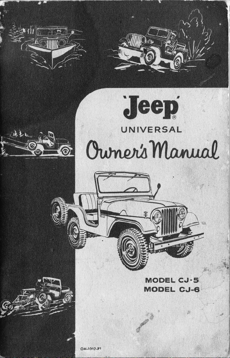
Jeen
U N IVE RSAL
Ourt
,o/..lmnxrrta/."
MODEL CJ.5
MODEL
CJ.6
Page 2
Y-
Jeep.
UNIVERSAL
4.WHEEI DRIVE
Model CJ-5
Model
Owner's
Willys Mofors,
lotEDo l, oHto, u.5. A,
Fom OM-1002-R3
Copyrighr
CJ-6
Mqnusl
Inc.
1960
Pdnr.d in u. s. a.
Page 3
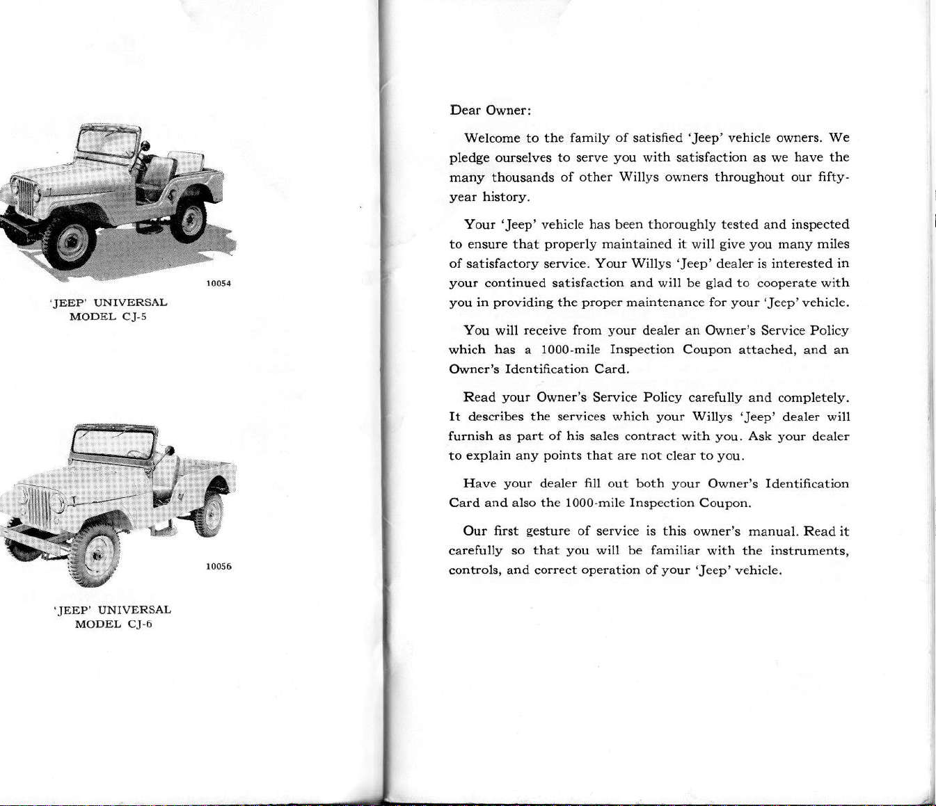
Dear Owner
I
.JEEP'
UNIVERSAL
MODEL CJ.5
v;
Welcome to the
pl€dge
many thousands
to ensure that
of
you.
you
which
Owner's Identifr cation Card.
It desdibes the services which
furnish as
to
Card and also the 1000-mile Inspection Coupon.
carefully
controls, and corect
ours€lwes to serve
Your
'Jeep'
satisfactory service.
continued satisfaction and will be
providine
in
You
Read
explain any
Have
Our fi.st
receive f.om
will
has a 1000-mile InspectioD
your
part
you.
gesture
so that
family oI
of other
vehicle
p.operly
Owner's S€rvice Policy caietully and completely.
points
dealer filI out both
has been thorcughly tested
piope.
the
of his sales contract with
that arc not
of service is this owner's
you
operation
satisfied
you
with satisfaction as we
Willys
maintained it
Your Willys
your
will be familiar
owners throughout our fifty-
'Jeep' dealei
maiotenance for
dealer an Owner's Se.vice Policy
Coupon attached, and an
your
clear to
your
you!
of
vehicle
'Jeep'
give you
will
glad
to cooperate with
your
Willys
you.
you.
Owner's ldentification
with the instruments,
vehicle.
'Jeep'
and
is
interested
'Jeep'
'Jeep'
Ask
manual.
owners. We
have the
inspected
many miles
in
vehicle.
dealer
your
will
deal€r
Readit
.JEEP'
UNTVERSAL
MODEL CJ.6
Page 4
IABTE O] CONTENTS
MANUFACIURER'S
The only
sold is that
recommended by the Autooobile
"This
OHIO, U.S.A.
by us,
normal
being timited 10
thereof, includine
supplied by the
(90)
purchaser
(6100
us with transportation
tion shall disclose
this warranty being
pressed
part,
assume
our vehicles.
shau
Willys Service Station
Manufacturer.
been subject to
The
liability
or trade accessory which
NOTE
times to revise, modify, discontinu€
vehicles,
or
it
the
Warranty under
of the
is to certify
to be fiee
use
days after
or before such
Km.),
implied and of all othei
or
and we
fo.
us any
have been
Manufacturer makes no warranty
for any defect
-Willys
or any
Selle!,
Manufacturer, being the Standard
that we,
warant each
f.om
and seryice,
making
all equipment oi trade accessories
vehicle manufactuler, which
making delivery
vhichevei
to our satisfaction to have been
er?lessly in lieu
neither assume
other liability
This warranly
.epaired or altered outside
to affect its stability
oisuse,
Motors,
part
or
incurriDg
which new Willys Motor Vehicles
Manufacturer's Association,
WILLYS MoToRS,INc
new motor vehicle manufactured
defects
in metal or other
in material and workmanship under
our obligation under thjs
good
at our factory any
of such vehicle to the
vehicle has been driven'1000
event shall first occur, be
charees
in
neslisence or
cannot be discow€red
parts
any
prepaid,
nor
shall not apply to aDy
way so as,
any
Inc., reserves the
thereof,
liability
WARRANTY
TOLEDO,
,
Warranty
part
(except
shall, within
returned to
and which
of
other var.anties
all
obligations or liabilities
authorize
in connection with
or reliability,
accid€nt."
o! change any
without
or
any other
in
the
against,
material
WILLYS
obligation
our examina-
thus detective;
person
the sale
vebicle which
of an Authorized
judgment
nor
which
nor assumes anv
in
by
right at any
notice; and,
part,
any
ordinarv
MOTORS,
models
the Purctraser.
to
Waranty
parts
or
tiles)
ninetv
original
miles
ex-
on our
of the
has
device
factorv
INC'
time
of
without
are
and
to
of
or
its
MANUFACTURER'S
SPECIFICATIONS
GETTING ACQUAINTED WITH YOUR
WARRANTY
. .. 6
rJeepr
VEHICIE
GENERAL INFORMATION.. ...,. ,
INSTRUMENTS. ........9
SWITCHES
OPERATING YOUR
AND CONTROLS.. . . . . . . . ......11
'Jeep'
VEHICLE
BREAK IN. 13
DRIVING THE
OPERATION
OF 4-WHEEL DRIVE:
'JEEP'
VEHICLE.... ..
. , , 13
r......
.. .. .
DRIVING TECHNIQUES IN 4-WHEEL DRItrE..
tUBRICATING YOUR'Jeep'
ENGINE LUBRICATION.:.
VEHICLE
.... 22
LUBRICATION CHART........,
SERVICE MILEAGE CHART.......
MAINTAININC
YOUR
'Jeep'
VEHICIE
POWER PLANT.....
cooLING SYSTEM..,.....
ELECTRICAL SYSTEM.
WIRINGDIAGRAM,.....
FUEL SYSTEM..
. - . . . . . . . . .
DRIVING COMPONENTS...
EXTRA
EMERGENCY
EQUIPMENT.,.
CHART.....
. ,
,.
..,.. ., .64
.. . . .........
Page
4
7
. . 16
. . 19
23
.29
30
35
38
39
.....4s
.47
....7s
'Jeeo'
APPROVED
SPECIAL
EOU|PMENI...........i7
Page 5
Tyte
Number ol C) iinders
Bore.
Strolre
Piston Disphcem€nt
Compr€ssion
Standard
High Altitude
Compr*ion Pressure .
Ho.sepower
Hors€power
Torqle
Ratio:
(BraLe
(sAE)
(Maximuh
cJ.6
Fuel Tank
Withont heat€r
With h€ater.
v€hicle weisht
cross
Weights approximat€:
Siip?ing
Curb
For.anvas
For canvas
For hard top model, add.
half
top
full-top mod€I, add
(opt.l
at 4000
.. . . .
at 2000.pr.)
(GWVI:
model, ddd
SPECIFICATIONS
3\"
1\'
rpn.) . .
.72
r5_63
al'
101"
43\6'
67"
l3srj'
r55r'
7r%'
U.S,
\at1sat.
cJs
2163 2223
ga1
1031
151
t7
72
15,63
cJ6
3 t7
21
GETTING
The follovins
tion about
The first section vill acquaibt
designations
The second
important break in
The thi.d section
tions as
The fourth section
syst€ms and components and
minor oaintenance
Prope. lubiication
lub cated
of lubricants, as
condition. You should
at an
your
and serial
section describes
vell as
periodic
the r€commended frequencies
at
Autho.ized Willys Dealer's
ACQUAINTED WITH
IJEEP'
GENERAI.
pases,
'Jeep' vehicle.
given
divided into four s€ctions,
numbers,
period.
covers lublicating
setricins requilements.
explains
procedurcs.
is most impo.tant. Your
in the third section,
periodically
VEHICLE
INFORMATION
you
instruments, and
proper
function
the
also
des$ib€s minor adjustments
have it
S€rvice Department.
When ext€nsive adjustments and lepai.s
peiformed
vork
your
Authorized Willys Dealer's
techniciaDs a.e
by a competent automotive repair
Service Depa.tment
familiar
wjth
your
'Jeep'
.epair recommendations.
All
information
the
recommendations
iDg and
se.vicing
given
in this owDer's nanual
that should be used as a
your'Jeep'
vehicle.
YOUR
contain informa'
with
specificalions, model
conlrols.
operation
proc€dur€s
to
lub.icated and inspected
se€m
vehicle
guide
includins thc all
and recommenda-
-
your
of
rJeep'
'Jeep'
vehicle
with the corftct
maintain
it in first class
necessary,
techniciar. At
aDd with all
consists of factory
prop€rly
lor
vehicle's
and
should be
srades
have the
the service
factory
operat,
Page 6
The vehicle
stamped
plate
the hood on the Ieft
vehicle.
Drefix
dieit
Model CJ-6
575,18-00000.
For
vehicle serial
on
is located
Model CJ's
57548
serial
ready rcIe.ence,
serial
a metal
on the dash
followed
number. The
is
57748.
number here:
VEHICTE
number is
Plate.
side
will
bY a
prefix
For examPle:
recoid
5ERIAT NUMBER
This
under
of
the
have a
five-
for
Yo'lr
I
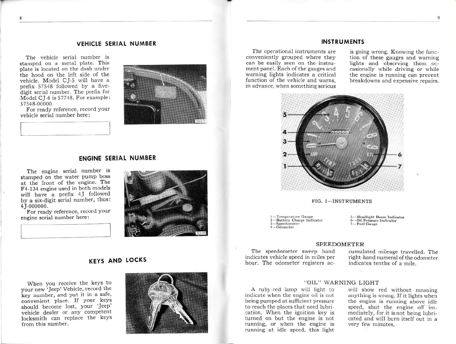
INSTRUMENTS
The opelational instruments
conveniently
can be easily seen on the instru
panel.
nent
warnine
function of
inadvance,
grouped
Each
indicates
lights
the vehicle and warns,
when something serious
olthe
where they
gauges
a critical
ard
are
is
lion
lights
casionalty
the engine is
breakdowns and exp€nsive repairs.
wro11g. KnowiDg
soins
of these
and observing them oc
gaug€s
while d.iving or while
running can
func-
.he
and warnnrg
prevent
The eneine
stamDed
on the
at tde front
serial
water
of the
F4.134 eneine used;n
will hava a Drefix
number,
by a sii'dieit
s;rial
4J-000000.
sedal
you
JeeP'
dealer
number.
reference,
number
receive
Veh;cle
and
Put
Place.
can
If
lost,
or any
rcPlace
here:
For ready
engine
When
your
new
number.
key
convenient
.hould become
vehicle
locksmith
from this
ENGINE
number
PumP
eneine
both
SERIAI
ls
Do3s
The
models
4J followed
thus:
record
Your
KEYS
to
keys
the
record
Lt rn a
Your
lrour
comPetent
the
the
sare
--keys
'JeeP
keys
AND
NUMBER
tOCKs
FIG. 1 INSTRUMENTS
SPEEDOMETER
The speedom€ter sweep hand
irdicat€s vehicle speed in miles
hour. The odometer registers ac indicates
,.OIL"
A rubl red
indicate when the e.sine oil is not
pumped
b€ing
to reach the
cation. When the ienition key is
turned on but the engine is not
running,
running
lamp will light to
at sumcient
places
or when the ensine is
at
that oeed
idle
speed, this light
per
WARNING
pressure
lubri
cumulated mitease
right
hand numeral
LIGHT
\till shov red
anything
the ensine
sp€ed,
mediately, for
cated and
shut the eDeine
6
7
travelled.
tenths of
is wrong. Ifit
is running
will burn itself out
of the odometer
a mile.
without neanins
lights
above idle
it isnot
beirs lubri-
The
when
oF im,
in a
Page 7
A ruby-red
indicate that
gen€rato.
ing the
key is turned
not runnine,
.unnine at
show
is not
battery.
idle speed,
red without
..AMP"
lamp will
for some
properly recharg'
When the
or1 but the
or vhen
reason
the engine
this light
meaning
WARNING
light
the
ignition
engine
will
any
to
thing is wrong.
engrne
as
will soo!
is
is
LIGHT
is running above
the charei'rg
have
soon as
comes
ins,
rect the failure.
Possible
so
on and stays
promptly
lights when
Ilit
ci.cuit
the battery
o.
dead.
If this light
on while driv-
detelmine
th€
idle sPeed,
checked
cor-
and
SWITCHES
AND
CONTROI.S
This
eause
is in the
fuel
will drop
mark when
turned
The temDeratufe
tempeEture
the
cooling
the
of the
(hot)
H
running
is
may soon
gate.
The
is that some
ing
antifreeze
€vaporated
a broken
If the
A ruby'red
headlishis
warns
shiline
The
is locat€d
up
The
sisnals
ti;n sienals
tu.n
fuel tank.
back
the
It may
off.
svstem.
gauge
zone,
dangerously
quit.
usual
in the
or leaked
radiator
"amp"
sre
that
inro itr.
sisnal
tuln
on the steering
position of the switch
right turn;
a
is sienalled,
indicates
to
tenit;on switch
of the solution
swings
it rneans
Stop
cause of
warning
light
on tictt U..m
your lights
how
The
Lhe E
take a
gauge
If the
far itto
the engrne
and
of the
radiator
out
heater hose.
or
lieht comes
HEADLIGHT
glows
or oncon.;ng
eves
TURN
indicator
the
a left
turn
the
green
.FUEL"
much
pointer
(emPty)
moment
.TEMP"
registers
needle
the
hot and
'nvestl
overtreat
water
has
through
wher
a"d
may
SIGNAL
switch
colum!
lever
do$n
Pos'
When a
lieht
js
in
or
BEAM
the
be
GAUGE
for the
isnition
The
meanins anything
vehicle
gauge
point€r
is driven
switch
may
to
is
over
GAUGE
the same
on at
fan bett
the
trouble
the
it has been
CAUTION.
.adiator cap
i.jury
ble
hot water. Never add
engine has
the
engine
the
IND]CATOR
driwers.
is
ssrl'h
indrcaro'
When the dimmer
push"d on"e
ha'k o low oPam
time,
has broken.
is, don't drive
corrected
Always
slowly to avoid
from escapins
to cool
rhe headlishls \^.ill
lishl urll
INDICATOR
wlren the
flash.
will
Dleted
;oins straiqht ahead.
i"ncitLi"g
lights
back
snaps
and
s''tcr'
as the
to centered
the
iever automatically
.ecord when
turned
again
fluctuate without
is wrone
roughterrar.
it may
or the engine
remove the
water
overheated;
first.
off
eo
turn
vehicle
will tu.n
the
as the
mean
Whateve.
on until
Possi
steam
when
allow
switch
anc
is
com
is
a8air,
the
off the
Position
on
or
rn'
seli
TGNITION
The ignition
and starting motor
switch ar€ integral.
located on the
the.ight
Turn
(clockwise)
right
ignition
When the
dash, below ard to
of the instrument
the key to the
to
and oank the
engine starts, iDmediately release the key
loaded to
automatically r€turn to
FIO.
2-VEHICLE
AND
This switch is
cluster.
extreme
connect the
eDsine.
as it is spring
CONTROLS
STARTER
the
the key to
rvhen the engi.e
the
and othe.
engine is not running,
key
clockwise)
SWITCH
position.
"on"
To
supply electric
batte.y to operate
to the ext.eDe
the
accessories
position.
Avoid
"start"
is runnine.
curent from
the heater
when the
turn
(counter
teft
tuoing
positioD
the
Page 8
LIGHT SWITCH
the
is the
control
The Iielt switch, No. 4,
pluflge.
knob is
type.
pushed
When
no lights are ]it.
in,
Pulling it out half way ope.ates
parking
the
lights and all the way
SHIFT LE\,ERS
The
"$hiftins
pattem"
ta$mission shift lever
figure 3 for
in
mission
and
the 3'speed
ffgure 4 for
the
of
is
shown
trans.
optional
the
HAND BRAKE
The manually operated brake
control is located uDder
of
of
hand
instrument
the
the steering column.
brake
panel
first depress the foot
the edse
to the left
To set the
HEATER CONTROLS
Check all controls
eration and turn
for
ch€cking
blower control speeds.
Thc air control knob whe'
atl the way out,
gives
air travel thrcugh the
and the amount
far
how
ture control
crease
(l€ft
the
pulled
k
the air flow heat output,
tum the ai. cont.ol
for ftee op-
air control knob
pulled
maximum
the
heater coils
of
heat depends
knob) tempera-
out. To in-
(center
knob)
on
out the
cluster light
parking
4-speed transmission. S€e
for operation of th€ transfer case
shiftine
brak€, then
brake control
handle
headlights. The instrument
is on when either
or the headlights
lights
levers.
pull
out
handle. Turn the
slightly and
on the
push
the
are 50
page
14
hand
it in to
which controls the blower speeds.
notch
One
and second
right for
to the
low speed
notch for high speed.
Pulline out defrcstff control
(right
knob) direcb warm air
throush the two deto€ters to the
wiDdshield. For Su'n'ler DrieirC
-Pull
out
air control
(cent€t
krob) only half way for maximum
fresh air to driver's compartmert.
OPER,ATING YOUR
By
takine a few reasonable
cautions
of
vehicle an opportunitv
"break
the wo.king
vehicle will be
The
vehicl€ ale
limits are maintained
Therefore
should be observed to
a0 Dph.
Carbon monoxide isa
lr
It
gasoline
.
.
.
the fille.
stick registeis
during the first few miles
driviDg and by
in", operatio!
parts
of
greatly
parts
[6s
no
hrs
is iD the exlaust fumes
odor. no laste. no color.
engines. Never
your
of
precision
certain speed
warm uP,
lah.l.
.0to300miles
MAKING
Fill
th€ radiato..
Put
sasoline
Fill
the oil reservoir
pipe
in
the tank.
until the oil indicator
FULL.
&GP
IN
-
mph.
The cmnkcase is filled
During
Be sure to have
dealer irspecr
at the end of 1000 miles
km.l
in a ctosed
the doors $ide
as the eneine is runnins.
READY
Give the vehicle a
.
See that
.
pre
your
of
BREAK
60 oph.
facto.y
viscosity for the
PROPER,
siving
properly
to
and life
your
'{Jeep'
ioproved.
This special oil
new
fitted.
'Jeep'
Close
th.oughout.
limits
"break
in"
at s00 miles
with engine oil of the
recommended
Section.
km.l of operation
not
do
km.]
[s00
CARBON
deadly
sas.
of all
sta.t an
indication of overheatins
component of the
vehrcle
vehicle
11.600
MONOXIDE
ensine
open
the engi'e.
lons
OPERATION
THE !'EHICLE
tlroush
Lubrica p.oper pressure.
See
lubrication
in the Lubrication
VEHICIE
kph.l.300 to
I80
L?h.l800
[95
with oil of
"break-in"
should be
kh.]
[800
in the Lubrication
the frrst 1000 miles
be alert for
vehicle.
usaee.
Keep then open
covering all the items
Sectior.
lires
all
See Ti.e
800
[1300
to 1200 miles
[2000
the
and rcplaced
vismsity
your
your
garage.
befde starti;g
cohplete
have the
Pressure.
mil€s
km.l
km.]
at the
proper
p€riod.
drained
U600
any
in
any
'Jeer"
'Jeep
Always
wide a;
Put
.
lever, Fie.
Place the
high shifr
gear
the fansmission
2, No. 14, in neutal.
transfer case low
lever. No. 8. ;n
or in lhe rear
disen8age the fronr
placing
th€ forward
.
fourth of
also open
.
the shift
position.
Pull
the choke
the way out.
Place the key
the thiottle sfigntly.
lever,
STARTING THE
searshift
and
direcl richr "
position
and lhe starter, Release
axle drive by
No.
7, in
cont.ol one-
This will
in the isnition
ENGINE
lock, No. 5,
right,
closins the ignition
Tu.n
.
the isnition key
and
turD
it to the
and hotd it there ro opdate
pressure
key when engine
Should the engine
.
at once,
pull
out and again
starts'.
fail to
the
choke all tlle wqy
press
tie starting
switch. When the engine
set the
operating
choke control at the
po6ition
and as the en-
circuit.
,,hard
on
start
starts,
best
Page 9
ginc
warms
the way in. Do
choke out as fuel
STARTING
Release the
.
Dcpress the clutch
.
Move the transmission
.
shift leve. to th€
figues 3
axte and traosfer case shift
front
levers are not uscd
vchicle is driv€n
in rcar wheel drive.)
D.press
.
pcdal gradually
timc slowly
pcdal.
Allolr the vehicle
.
mcrtum
lcngth!), ther
and depr€ss the clutch
tor
atlhe-same
Mo!€ tne shift
.
to
DcFcss the foot
gredually
llowly release the clutch
ramc
(29-32
cclerato! and depressing the clutch
pedal
ncxt higher
thc
Shift to
.
way at
tm./ttr.), releasins
before
push
up,
THE VEHICLE
and
the
relcase
(two
moment.
and at the same
'tigh"
about
moving
thc choke
not run with the
is wasted and
hand bmke,
pedal.
position.
first
(Note
4.
on the hishway
foot
and
or thrce v€hicle
rel€ase
accele.ator
that the
when the
acccleratoi
at the same
the clutch
gain
to
the accelera-
p.omptly
lever
speed
speed
18 to
shift lever.
the
if set.
sear
See
mo-
pedal
position.
pedal
time
pedal.
in
20 mph
the ac'
STOPPING
Rclease the foot accelerator.
.
Appty
.
vehiclc is
t1le foot brake
nearly
and thm depress the
practic€
Th€
of appltns the brakes
intermittently ratler tlan
coDstant
pressu.e
a sta.dstill
at
clutch
will
until the
pedal.
with
result in
CHANGING
lower
pedal.
quick-
lcwer
speed, in-
Depress the
.
Mov€ the
.
into the
ly
clutch
gearshift
ncxt
all
tlle
the engine
Should
.
th€ Emergeocy Chart.
see
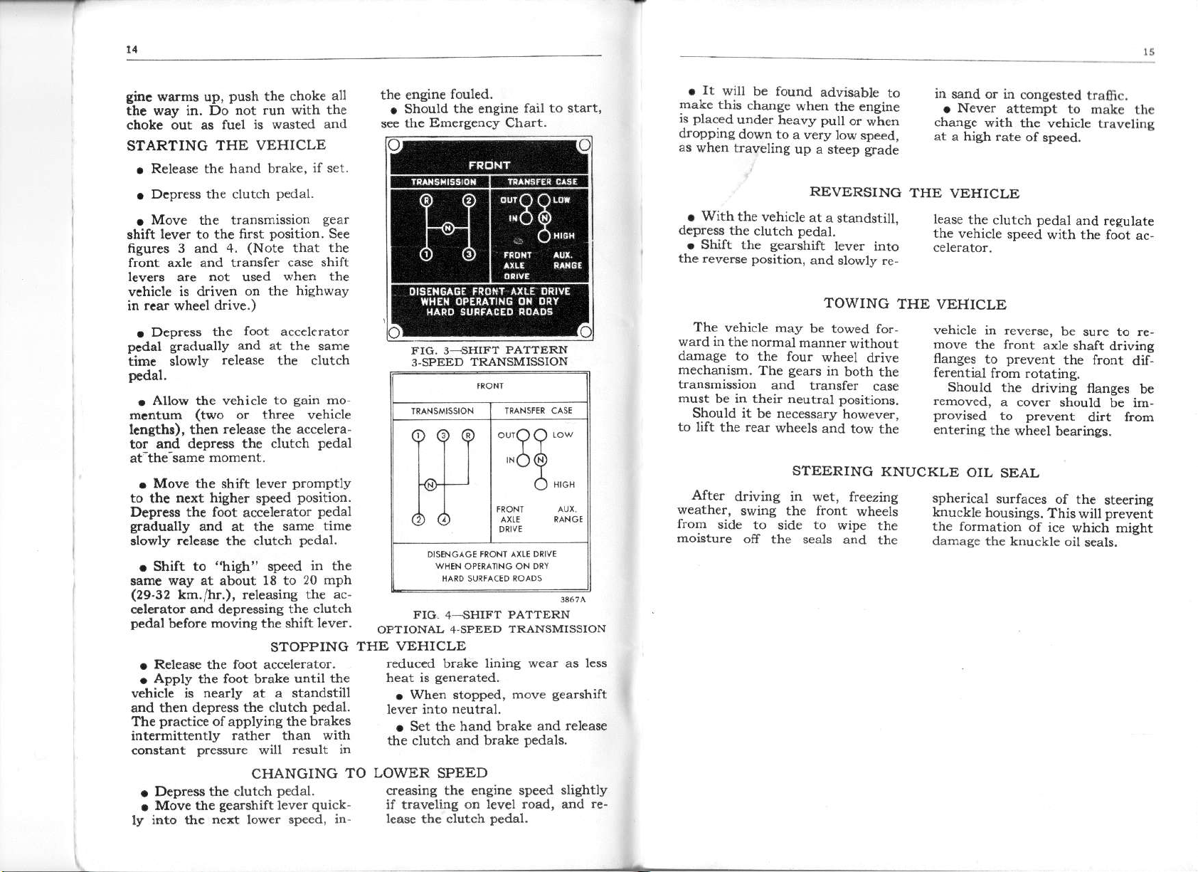
FIC. 3-SIIIFT
3.SPEED
FtG
4
OPTIONA! 4 SPEED
THE VEHICLE
reduc€d brake linine wear as lcss
When stopped, move
.
lever into
S€t the hand brake
.
the clutch and b.ake
TO LOWER SPEED
creasing th€ engiDe speed
if t.aveling
lease
the
clutch
fouled.
the engine
ARANSMISSION
fail to start,
PATTERN
*.ee
^dd
d
-SHIFA
neutral.
on tevel road, and
PAAAERN
ARANSMISSION
and release
pedats.
pedal.
gearshift
slightly
r€-
It
.
will
make
placed
's
dropping
as
when traveling
With
.
deFess the
Shift the
.
the reverse position,
The
ward in
dMage
mechanism.
transmissioD
must
Should it
to lift
be found
this
chanee
under
down to
the vehicle
vehicle
the normal
to the fou.
be in their neutral positions.
.ear
the
when
heavy
a very
up a steep
clutch
pedal.
gearshift
may
mannerwithout
gearc
The
and transfer
necessary
be
wheets and tow rhe
STEERING
After
weather,
from
moistu.e
driving in wet,
swirg the front
side
to side to wipe
otr
the seals and
advisable
the engine
pull
low spe€d,
or
to
when
grade
REVERSING
at
a staDdstill.
lever into
and stowty re-
TOWING
be towed for-
wheel drive
in
both the
case
however,
KNUCKLE
f.eezing
wheels
the
the
in
s.and or in
Never
.
change
at a high rate
with the wehiclc
THE VEHICLE
lease
the clutch
the
vehicle speed
THE !'EHICLE
vehicle in reverse,
move
femoved,
provised
the front
tlanges
ferential
Should
entering
to
OIL
spherical
knuckle
housings.
the formation
damase
the knuckle oil
congestcd
attempt
of sp€€d.
pedal
with the foot
axle
prevent
from rotatins.
the
drivine nanges
a cover
to
the
wheel bearings.
should be lm,
prevent
SEAL
surfaces
of the
This wilt
of ice
tra6c.
to make
and
be sure to !€,
shaft driving
the flont
dirt from
thc
travcling
regulate
ac
dif,
b€
steerins
prevent
which might
seals.
Page 10
To shilt frcrn
2-whael-drive
to
acc€lerator,
move
and
to the
auxiliary-range
hish
front axle
ifth€ vehicle
the
forwa.d
(rear) position before the
drive can
4-wheel-drive
front'axle
(out)
levei
WHEN TO USE
Use 4-wheel
additional
for difficult
ing
provide
fo.
You should
when
are
by the
surfaced
should
tractive
needed under
longed
ha.d-surfaced
ally caus€
shiftins
condition
low speed
industrial and
greater
required than can
standa.d
normal drivins
For
not be used.
effort
use of 4'wheel
out
drive
traction and
.oads, 4-wheel
temporary
is
terrain and
asricultural
only use 4-wheel
traction
transmission
WI{EN NOT
it
P.ovides
such conditions
roads may occasion-
of 4 wheel d
caus€d
let up
be disensased
The additional
on the
is moving,
drive lever
Position.
must be in
to
Provide
lowe.
and
be
Provided
on
drive
difficulty
we. This
build-uP
Power
Power
is
Pulling
by a
The
sear
us€.
drive
TO USE
hard-
drive
Pro
to
low
not
on
in
-'?o*-
'"o
4'WHEEL
gear.
road when
$ow. Us€
rolling
imptements. Use
mud, sand,
2 wheel-drivc
job.
4.WHEEL
of torsional stress
train
variatioDs
differeDt load
drive
several
su
DRI\E
4 wh€el drive
Use
it to
and
and
in tirc diameterc
rclieve tnis buitd-up,
To
the vehicle
feet
Domentarily to allow
ace
I
o',""
need it. Use it
vou
get
heavy trailers
pullins
for
and wherever
traction
DRI\E
results from
conditions.
or dfive otr the
agricultural
it on
won't do the
iD the
reverse for
in
10032
otr the
in
ice, hitts,
normal
drive
normal
uoder
simply
hard
the
DRIVING
THROUGH
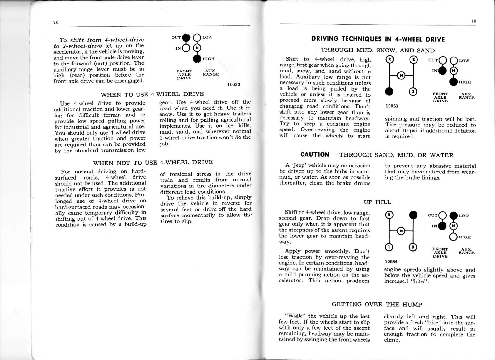
Shift to
range, first
mud,
snow, and
load. Auxiliary
necessary
a load is being
vehicle
proceed
changins road
shift into
necessary
Try
to kcep
speed. Over
will cause
A'Jeep'vehicle
be
driven up to the
mud, oi
thereafter.
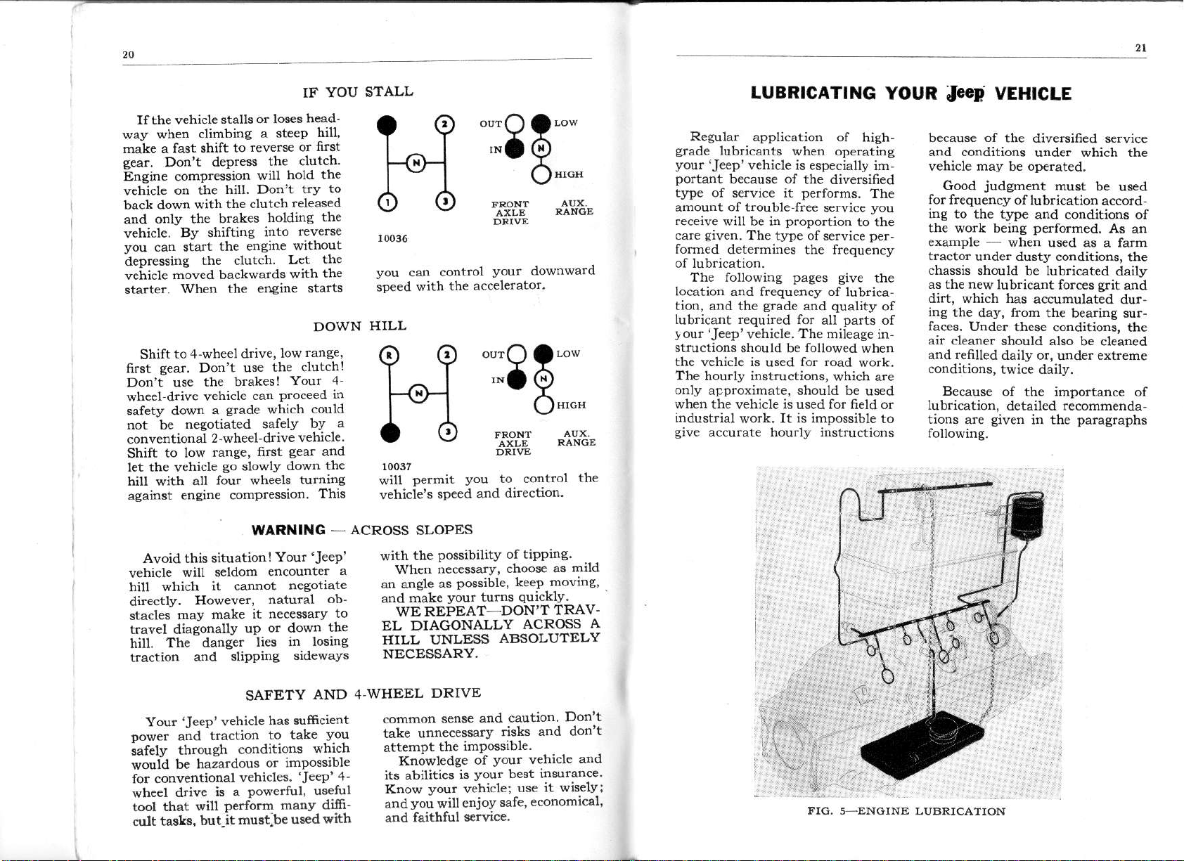
Shift to 4-wheel
second
g€ar
only
tie st€cpness ofthe
the lowe.
4-wheel
gea.wheD
in
or unless
more
low rans€
such conditions
slowly
coDditions.
aDy lower
to oaintain
a constant
rewing
the wheels
CAUTION
water. As
clean the
Drop
sea..
when it is
to
sear
TECHNIQUES
MUD,
diive, hish
goine
sand without
pulled
it is
throush
is not
unless
by the
desired to
because
gear
Don't
than is
headway.
ensine
the engine
to
sta.t
of
IN 4.WHEEI.
SNOW. AND
a
sDinning
Tire
about l0
THROUGH SAND, MUD,
may
on occasion
hubs in sand,
sooD as
d.ive, low range,
asc€nt requires
maintain
possible
b.ake drums
dow! to first
apparent that
head-
UP
to
that
ing
HI
LL
9?
SAND
10033
and traction
p.essure
psi.
OR WATER
prev€nt
may
the brake linings.
any
have eDtered from
l-o-l
DRIVE
o,rr.)
a\,"*
,"-
6
a*"
may be reduc€d
il
additional flotation
will be lost.
abrasive material
."Q?--
*o
Q
o"*"
to
wear
Apply power
lose traction by
ensine. ID
way
a mitd
c€lerator. This
"Walk"
few feet.
with only a few
remaining,
tain€d by
certain conditions,
can be maintained
pumpins
the vehicle
If the whecls
headway
swinging the front
smoothly. Don't
ovei-rewing
head-
action on
action
by using
the ac
produces
GETTING
up the last
start to slip
feet of the
may
ascent
be
wheels
main-
dd
tle
OVER THE HUMP
10034
ergine
below t}le
sharply left
provide
face
enough
climb.
speeds slightly
a fresh
and witt
traction to
vehicle speed
.isht.
aDd
"bite"
into the
usually
comPlete the
above and
gives
and
This
will
su.-
result
in
Page 11
Ifthe vehicle
when
way
male a fast shift to
gear.
vehicle
back dowr
vehicle.
Dont depress
Ensine compression
on the
only the
and
you
can start
depressing
vehicle
starte!.
6rst
Don't use
wheel
safety down
lot be
conventional
Shift
let the vehicle
hiu with
agaiost
moved backwards
to,1 wheel drive,
Shift
gear.
drive vehicl€
to low
stalls
climbing
hill. Don't
the clutch
with
brakes
shifting
By
the engire
the clutch-
WheD
engine compression.
the el}gine starts
Don't use
brakes!
the
a
srade
negotiated safely
2 wheel drive
ranse,
so
all fou. wheels
or loses
a steeP
reverse or
the
wiu
holdins
into
low
the
can
Proceed
whicb
first
slowly
YOU
IF
head-
hi[,
first
clutch
hold the
try
released
the
reverse
without
the
Let
the
with
DOWN
ranse.
clutchl
Your 4
could
by
vehicle
and
sea.
the
down
turnins
This
to
STALL
LUBRICATING
YOUR
JEED
VEHICLE
.'.oo--
??
ro-1
,".
Q
o*""
oo
10036
your
you
speed
can control
the accetetator,
with
downwarcl
HILL
."'a
9?
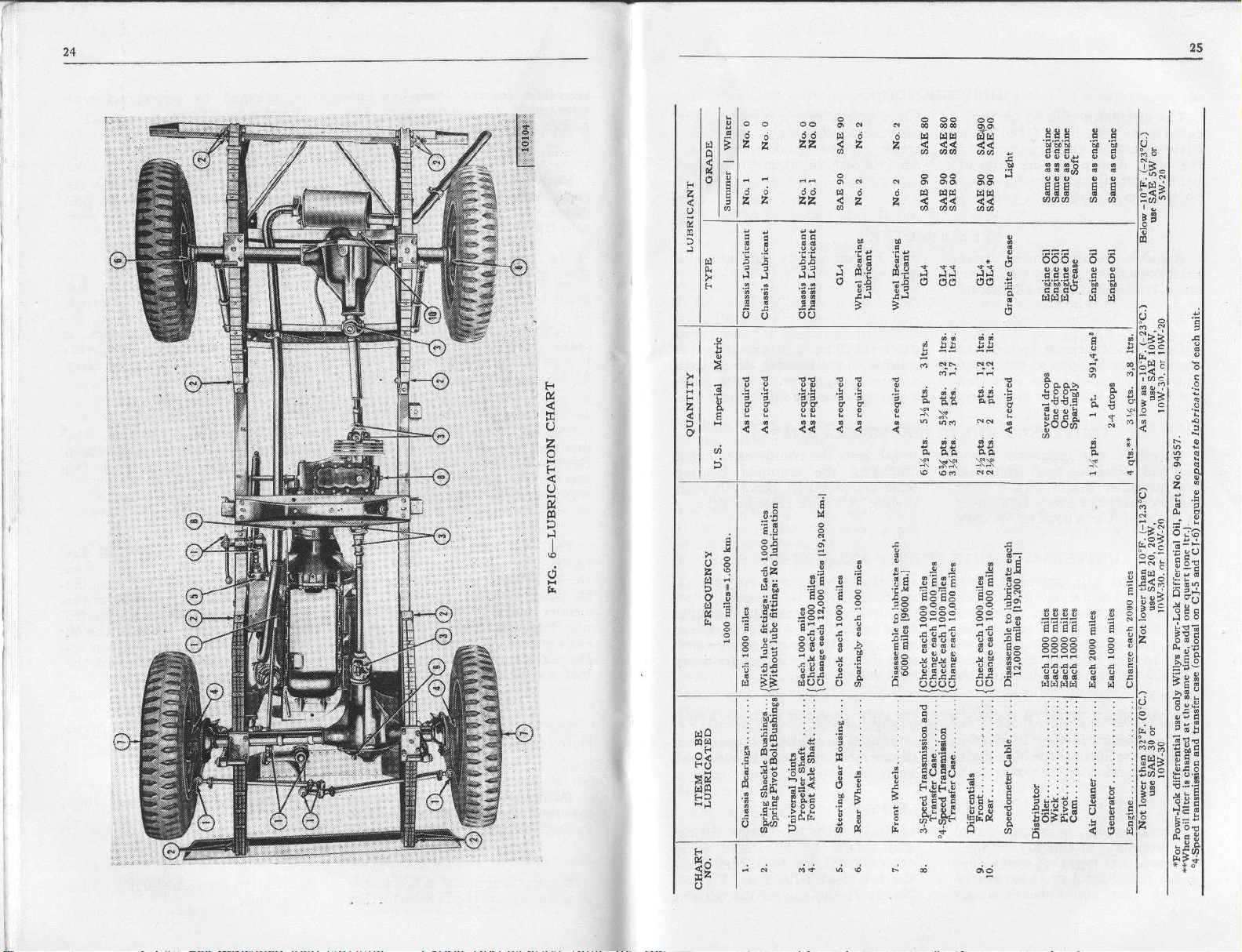
in
a
tG
^a
?--
ri)
6.".
Jd
1003t
permit
will
vehicle's
you
speed and
to control
direction.
the
Regular
srade
your
'Jeep'
portant
tl.pe
amount of trouble free
.eceive
care
eiven.
foroed
The following
iocation
tion,
and the
lubricait required for
rJeep'
our
I
structions should
the vehicle is
The
hou.ly instructions,
oDly
approrimate, should be
wheD
industrial
give
accurate hourly instluctions
application of
lubricants
vehicle is
because of
of
service it
will be in
The
determines the frequency
ard fr€quency of lubrica-
vehicle. The mileage
the vehicle
work.
when operating
especially im
the diversined
perfo.ms.
service
proportion
t].pe of seNice
pages give
grade
be
used
is
It is impossible
quality
and
all
followed
for road
which are
used for field or
parts
high-
The
you
to the
per-
the
of
of
in
when
work.
used
to
because of
aDd conditions
vehicle may be operated.
Good
for
frequency of
iog to the type
the work beins
example
tractor
chassis
as the new
dirt, which has
ing
the day, from the
faces.
air creare.
and refilled
conditions,
Because
lubrication,
tions are
followine.
the diversified service
unde. which the
judgment
when
unde. dusty conditions,
should be lubdcated
lubricant fotces
Under these conditions,
should also be cleaned
daily or, under extreme
twice daily.
of the importance of
detailed recommenda
given
must be
lubrication accord
and conditions of
performed.
used as a farm
accumulated dur
bearing su.-
in the
used
As an
the
daily
grit
and
the
paragraphs
Avoid this situation!
vehicle
hill which
directly.
stacles
travel diagonally
hill.
traction
wiII seldoo
it cannot
However,
may make
The danger
and
slipPing
uP or down
SAFETY
Your
Dower
safely
vould be hazardous
for
wheel
tool that
cult tasks,
and
throush
cooventional
&ive
vehicle
'Jeep'
traction
conditions
vehicles 'JeeP'
a
is
Powerful,
perform many difi-
will
but-it
must be
WARNING -
Your
encounte.
natural
it necessary
lies
'JeeP'
nesotiate
obthe
in losing
sideways
AND 4'WHEEL
has sufficient
to take
or impossible
vou
which
useful
used with
ACROSS
a
to
4'
SLOPES
with the
When
an anele
and make
possibility of tiPPing.
necessarv,
as
Possible,
your
tums
WE REPEAT'-DON'T
EL DIAGONALLY
HILL UNLESS
ABSOLUTELY
NECESSARY.
DRIVE
and caution
common
tak€ unnecessary
attemPt
Knowledee
its
Know
andyou will
and
sense
imPo€sible.
the
of
you!
your
is
vehicle;
enjoy
abilities
faithful service.
risks and don't
your
safe,
choose
as mild
keep moving,
quickly.
TRAV-
ACROSS
Don't
vehicle
best insurance
it viselyi
use
economicat'
A
and
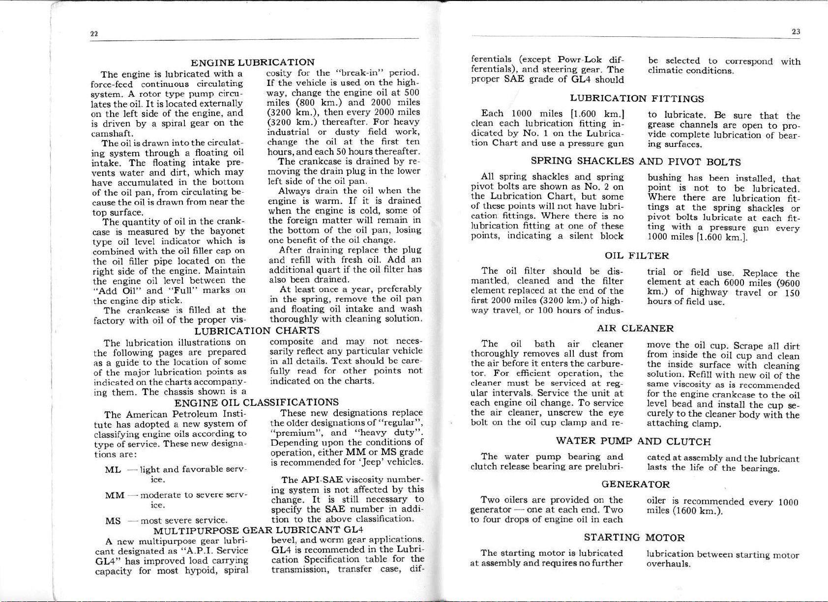
FIO, s-ENGINE LUBRICAAION
Page 12
22
ENGINE
The en{ine
forcc-feed- continuous
svstem.
t;tes the oil. It is located
on the left side
is
&iven
camshaft.
The oil
ine system
iniake.
wat€r and dirt,
vents
have accumulated
of the oil
caus€ the
roD surfacr.
the au€ntitv
is measu;ed
case
tlT€ oil level
combined
the oil
risht side
rhe eneine oil level
Oil"
"Add
enq;ne diD slick.
rhe
The- crankiase
factory
The lubrication
the followins
as a euide
ol th;
indicated;n
ing them.
The
has adopted a
tute
claslifyins
twe ois&ici.
are:
tions
ML - Iisht and favorable
MM -mod€mre
MS
is
lubricated
A rotor
is
The
;il is
fiIle.
with
major
American
(ype
of the eogine, and
spiral
by a
drawn
pan,
with
of rhi engine.
The chassis
into the
lhrough a
floatine intake
from circulating
drawn
of oil in the crank-
indicato. which
the oil
oiDe
and
"Full"
oil of the
pages
to the
lubr;cation
lhe charts
Petroleum Insti
e;sine
rnese
-ice.
most severe
Pump
gear
in the bottom
from
by the bayonet
located
betw(en
filled at the
is
illustratioDs
are
location
ENGINE
new system
oils accord;ng
new desiena
to severe
MULTIPURPOSE
A new multipurpose
A.P.I. S€rvice
cant desienared
GI-a' has
capacity
as
improved
for;ost
load caryins
hypoid, spirat
LUBRICATION
with a
circutating
circu
exlernallv
on the
circulat
floating
$hich
filler caP on
marks on
proper
LUBRICATION
a.companv
shown
o;l hours, and
pre-
may
be'
near the
is
the and
or
Mainrain
lhe slso
vis
on composite
prepared
of some
points
as
is a
OIL CLASSIFICATIONS
of
to
serv.
s€rv-
servrce.
GEAR
tub.i bevel,
eear
cositv for
If the vehicle
wav change
miles
(3200
(3200
industrial
chanee
The crankcase
moving the drain
left side of
Alwavs drain
eneine
when
rhe foreisn
lhe bo(tom
one benefit
Afte.
addirional
At teast once a
in the spr;ne,
and
thorouehlv
CI{ARTS
salily
in all details. Text should
fullv
indicated
These new desi$ations
the older designations
premium".
Depending
operation,
recommended
rs
The
:^^,
irE";..
"p."&
tion to the above
LIJBRICANT
GL4
cation
trans'nission,
the
"break-in"
is used on the high'
(800
km
km
rhe ensine is cold. some
refill
been drained
fioaring oil intake and
renect anv
the engine
kln ) and
everv 2000 miles
then
),
thereafter.
)
or
the oil at the fr.st ten
is wsrm. If it is drained
read for olh€r
dusty
each 50 hou
the oil
maner
of
the
of
the
draining
with
quarl
remove the oil
with cleaning solution
and mav
on lhe charls
field wo.k,
rs
is
drained
plug
in the lower
pan.
the oil when
will
oil
oil change.
replace the
fresh oil Add
if the oil
vear,
particular
of
healv dutv
and
upon the condirions
for
or MS
'JeeP
€ithet MM
API-SAE viscosity
system
is not affected
r. i" still
tt'" Sls
number io addi-
necessatv
ctassification.
GL4
and worm
is recommended
Specificalion
applications.
sear
in the Lubri
table
transfer
Period.
oil
al 500
2000 miles
For heavv
thereafter.
bv re
the
of
remain in
pan.
Iosins
plug
an
6lter has
prefetablv
pan
wash
not n€ces-
vehicle
be cate'
points not
replace
"resular"'
grade
vehicles
number-
bY lhis
for th€
case' dif-
of
to
ferentiats
ferentials),
proper
Each 1000 miles
clean each lubricati@
dicated by No. 1 on the
tion Chart and use a
All
pivot
the Lubrication
of thes€
cation fittings. Where there
lub.ication frtting at one of
points,
(exccpt
and
SAE
steering
grade
Powr Lok
sear.
of
GL4 should
LUBRICATION
[1.600
fitting in-
Lubrica,
pressure
SPRING SHACKLES
spring shackles and
bolts are shown as No.
points
indicatins
Chart, but
rot
will
a silent
have lubri-
dif-
The
km.l
sun
spring
2 on
some
is no
these
block
b€ selected
climatic
to
conditions.
corespond
FITTINGS
to
lubdcate.
grease
vid€
AND
channels
complete
PIVOT
bushins has
point
is Dot
Where
tings
at th€
pivot
bolte tub.icate
there
Be sure
are oDen
lubricatlon
BOLTS
been
to
are
spring
ting with a pressure
1000
miles
[1.600
km.].
with
that the
to l)ro-
of bear-
installed,
that
b€ lubricated.
tub.ication
shackles
fit,
or
at each fit-
guD
every
OIL FILTER
The oil filter
mantled,
element replaced
firut 2000 miles
vay travel, or 100 hours
cleaned aDd the filter
should
at
(3200
the
end of the
km.)
be dis-
ofhigh
of indus-
trial
or field
elemcnt
km.) of
at
each 6000
hishway
u*.
Replace
miles
t.avel
(9600
or
the
150
AIR CLEANER
The oil bath ai.
thoroughly
the
air before
tor. For efficient ope.ation,
clean€r must be selviced
ular inteNals. SeNice the
each engine oil charge. To
the air clean€r, unscrew the eye
on th€ oil
bolt
removes
it
ente.s the carbure-
cup clamp
all
dust
cleaner
from
the
at reg
unit at
service
re
and
move
the
from
inside
the iDside
solutior.
same
for
level
curely
attaching
Refill
vrscosity
the engine
bead
to the
oil cup.
the oil
eurface
and insta)t
cleaner
clamp.
Scrape
cup
with
with new
as is recommended
crankcase
bodv
a
and clea,
cleanine
oit of th;
to the
the
cuD
witL the
dirt
oi1
s€_
.
The water
.elease
clutch
WATER PUMP AND
pump
b€a.ine are
bearing
pfelubri-
and
cated
lasts
CLUTCH
at assembly
the life
and the
of the
lubdcant
bearings.
GENERATOR
Two oilels
generator
to four drops of engine oil in each
The
--
starting
at a$embly and
provided
are
one at each €nd. Two
oD the
STARTING
motor is
requir$ no
lubricated
furthcr
oiler
is recommended
m']es (1600
MOTOR
lubrication
km.).
be8reen
every
1000
stating motor
Page 13
21
?5
tl
tl
tl
tl
tl
tl
l"l
lEl
7
I
I
cd
3^ . 333 C3
E5
J-6
:2
"
Ei :-
"
E a I
i:
i:
,"i .i Be'.,5 F
j-
Hca oJd
. ,: ii
,\
iza
uu
E53_
;:; F E
t 3
g
?
6
ij
;;
1:.
-li-
a
.h--
3t-z
t!l
t€ x! E z
ct I e
z
F
!
r
_r I
i
'.i
El
e,6 ; i
F
d
8i
;2 t ! i-
:C
s,F
s
E
i:
;!:
':?
q
i3
:E
: *6
q
.9.
8-* 5--
"
a
iE :
E
lEr
;
Eli
jjj
i
::
g!6
d
";<i;3;Fr
r !.i
t
3
E ;J
i ;E
;
F
€
t
b
a
tE+E ;€
:;a;
!i;i
ii
;E
ic;5
:
:.:
q.E
i!
, i.i Ei
: ;i;t i
f
r*fF E
rl
i
!'l
;:
Ei
,; iill
ir
;5i:
EiEi
iE
**
3
€
b
3
t
?
6
!
,i
r
E
i i
F
:
i
E
ts
d
,l;!
:lt
!l
i
li
IE
il
: nc
3 t:
:;
i'
!i
6l^
,13
l'^;
l;-;
z
el:
;13
,5lz
t:l
iil
l!l
i!l
!l
l;
l3 sl
ld Sl
i:.gl
la' el
gl
lj
l:i.l
i!!:l
ril
t;
g:l
ij
5*rl
|
t0,sl
t:€51
l;ril
t:E:l
l3:El
l!€:l
t!E;l
gI
IT€
l€:?l
/.tE Fl
li;:l
ld.!l
lF:"1
ll
Page 14
DISTRIBUTOR
The distributor should be lubri
evely 1000 miles
cated
aeveral
Place
oiler. Also
the
drops
light ensine oil
on thc top
of
place
on
the shaft, which
(1600
of engine oil in
one drop of Apply a drop ofoil on
the wick located aim
km.). rotor
made
srease
is
SPEEDOMETER
Remove the speedomete. drive with a
shaft from the tub€
it thoroushly
clean
once each
and
year, grease.
lubricate
STEERINC GEAR
Check the tubricant lewel in the ins
steerins
miles
the lubdcant is at
gear
11.600
housing at each 1000
km.l to be sure that a hand compressor.
fi1le.
UNI\ERSAL
Lubdcate the univcrsal
and slip
rcar
quality
11.600
joints
propeller
lubricant
km.l.
Use
for both f.ont and damaging
shafts with a
every 1000 Diles
a hand compressor
UNIVERSAL
front axle
Thc
arc cnclosed
housings which are
cant. Check cach
km.)
fillcd to
(12,000
bc surc the housings
to
plug
mile!)
UNIVERSAL
universal
in the steering lnuckle
6lled
1000 mil€s
l€vel. Once
(19,200
JOINTS
plus
open- look replacing the filler
JOINTS
joints
good
JOINTS
joiDts
with lubri oushly
(1600
are aDd
year year
each
km.) the field
(POWER
quired,
(PROPELLER
to lubricate
seals which might
the use of a high
(FRONT
axle shafts and
semblies should
TAKE-OFF
Thc original factory lubrication otris
will lsst thc
avcrsg. servic€.
Front whe€l b€arings
removed, tnoroughly
be
ch€cked, and repacked e!€ry
miles
The rcar whccl bearings
lifc
[9.600
ofthe v€hicl€ under disass€Dbl€
power
If
tnc
take-
WHEEL
BEARINGS
should equipped
cleaned,
6000 1000 miles
km.l or twice
yearb..
are No. 1,
accessible by
removing
a!m. Sparingly apply soft
on the
breake. arm cam.
pivot.
sood
quality
lisht
level. Should lubricant
fill
the housine stowly
SHAFT)
tl|e tunnions to
tle trunDion bearing
occur through
pressure guD.
AXLE
SHAFT)
unive.sal
r€moved,
be
cleaned and the
filled with fr€sh
.epack
lubricant.
the housings
if the vehicle i5
wo.k.
PROPELLER
used for continuous
and repack
year.
with tubrication
and should be
the lublicant
et tlle top
lubdcated ev€rv
km.].
[1.600
relief
of the howing
the
the breaker
e.aphite
.e-
be
with
Do not over
plug.
avoid
joint
as-
thor-
housines
Clea;
twice
each
used for dusty
SHAFT)
opcmtion,
onc€
cach
frttings
Fi'st cha;r
hol€, Fis. 33,
and then lubricate sparingly
gua.d
asainst surplus oil saturating
the brake linings. Llbricant flow
HAND ERAKE
Lubricate all bea
pins
of
each 1000 miles
the haod brake control
ngs
[1.600
and clevis
km.]. Lubri-
BRAKE MASTER CYLINDER
Check the
master
11.600
the filter
area around it. Replenish the
fluid
to a leyel
fluid
level in the brake
cylinder every 1000 miles
km.l. Wipe
cap and abo
ctean the top of
the housiDe
rZ"
lr,3
cm.) be\ow
bmke
the top of the fiII hole. Use only
CHOKE CONTROL
Lubricate the exterior su
of the flexible conduit with
aces
pene'
CLUTCH LINKAGE
Lubricate
the clutch linkage every 1000 miles
[1.600
ofengire oil as used fo. the engine.
Failu.e
km.]. Use the same
to lub.icate these
all
friction
points
grade
points
of
TRANSMISSION AND TRANSFER
Drilled
standard three-speed transmission
and the t.ansfe.
permit
between the
each
Optional four-speed transmission
and transfer case housings
provbion
cirolate between them and
be serviced separately.
Check the oil level
m es
each unit every
(16,000
NOTE: The lubricant
passases
lubricatine
two units- Howewer,
unit should
for lub.icating
(1600 km.). Drain
or
km.)
between the
case housiflgs
oil to circulate
be seNiced
10,000 miles
hours of field
300
have no
every
and
capacity
oil to
musl
1000
rcfitl
to
ing
out the relief hole
properly
bearing
is
indicat€s
filled.
CONTROL
cate the b.ake cables
inside
*"n 1o'ooo miles
ffin"
heaa'1,
will result in
links
the mating
of the housings
my,
lubricant
hours when the
dusty field work.
geals
indication
lub cant is eithcr
srade
congeal at the
ture.
ably
ditrerentials.
to attow ease of
beavy to
close fitting
lubricant to a lighter
delay.
duty b.ake fluid
to specification
su.e to handle the
clean dispeft.rs
conforming
SAE-70,R1.
brake fluid
and
containe$
that will not introduce
slightest a.rnount of other
Replace
and tighten thc fille.
oit
every 1000
mircs
lntinc
premature
will wear and
parts
CASE
it is
so
vcry important
be changed
Eard shifting
in
cold weather
that the
or the
quality
p.evailing
This condition
apply to the transfer
If the oil is
properly
parts.
the holes in
will
is
small fo! €cono-
every
vehicle is
of the transmis€ioD
is a
trarsmission
too
allo,i's
will also
too heaw
shifting, it
lubricate
Change
grade
thc
thc
[16.000
even
the
liquids.
cap.
11.600
wear;
thc
bccome
that
the
300
used for
pGitivc
hcavy
it to
tempera-
prob-
caae
and
ir too
thc
the
without
Be
in
a
Page 15

level in the
Check
thc
tial housings
Ir.600
km.l to be sure
irbricant is at
plugopenings.
Some
every
not mix ditrercnt
vehicles
ditrerential
housins
km.l. Do
locking
ment). Lockine
plate
brass
under
?
screw
distinsuish
Ordinary
stamPed
one
heads
(Fig.27, item 17)
it from standard
lubricants
The vehicle
be lubricated.
leaves are
lasting
designed
coated
special lubricant
to last
every
1000
that
the level of
Draib
10,000
mil€s
refill each
and
POWR-LOK
equipped with
ate
(optional
ditrerential
with the
of the
gear
musf
ngs should
sp
At assembly
with a
the life
DIFFERENTIALS
difreren-
Dites
the
the filler
116,000
of lubricants.
or light
the
ditr€rentials).
steam,
flushing.
tYPeE
DIFFERENTIAL
be used
equip-
lEe a
Use
ential
letter
cover
to
dif
Do not flush the Powr
ferential.
vents
not
SPRlNGS
springs.
mixture
tendency
from between
long-
which
not
the
is
of the
flushing
hoLrsins
only Willys
(except
kerGene,
in the locking
Oil, Part
The use
of any
Spraying
of oil and
to wash
light
Use
Do
kind is not
the spring
to clcan
oil
on Powr-Lok
not use water,
or
easoline
ditrerential.
Powr Lok
No. 94557,
of
cl€aning
with the usual
ketosene
this lubricant
eneine oil
out
for
Ditrer-
furnish-
Lok dif'
sol
recom-
has a
leaves.
F
E
o
:.^
F !!
E
E.; E
si
iv
b;
b
.9;
F
Z
o
gu
>
i
p
Check
nor housing
Use
POWER
Check
lubrication
lubricant
the oil level
oil of the
TAKE.OFF
the lubdcant
at
in the
each lubrication.
at
job,
filter
glade
same
maintaioine
plug
level Should
level
GOVERNOR
gove.- the
in
used
SHAFT
AND
at each
the
ensine
housing at each
PULLEY
power
the
quendv,
hours.
300
Drain and
DRIVE HOUSINGS
take-o$ be used
change
refill the
ensine
the
oil change'
lubricant each
fre-
U
>
v
A
;*:
433
",9-
"EE
,bE€
:i
:i'
E
36I
E
I
a
6
9;a
.!
-
6
o
tt
i
o
I
;
E
Page 16

3t30
MAINTAINING
ProDer maintenance
'Jeep'-vehicle
qiven
a
tion and
miles
Such
careful
by
to locate and
faults that
Prompt
thus discovered
holdins
and
I1.600
an inspection
road
a competent
down
costly delays
Your 'Jeep'
best
For
p€ndability,
a tune-up
in the sp.ins
Proper
include
Clean
.
terminals,
cable
connection
right side
front eDgine
Remove th€ spark
.
them
electrqles
thoroughly
Check valwe
.
Remove
inspcct the
and
Adjust ihe
mm.l
sap.
check
.
demands
thorough service
lubrication
km.l of operation
test
and
se.vice
analyze any
may have developed
correction
will
maintenaoce
vehicle dealer
performance
the engine
yearly, preferably
twice
and
tune-up
following:
the
and tight€n
the battery
and
sround
of tlle
support.
.030/
to
t}te distdbutor
points
tne isnition
POWER
PERIODIC
of
You.
that it be
inspec
at €ach 1000
consists
examiDation
of minor faults
go
in operation.
should
fall.
proceduie
strap
engine at the
plugs,
and sPace
10,76
clearance
contact
to.020"
ADJUSTING
of a
technician
small
far toward
expense
ENGINE
and de-
should
the battery
ground
on the
clean
mm
l
Points.
timing. See
YOUR
INSPECTION
is
TUNE-UP
havc
the
gap.
See
caP
10,51
:FED
VEHICLE
PIANT
vitally interested
vehicle and
regularly insp€ct
him
dealers'
the advantage
specifications
as
regularly sent
The follo\rins
methods
ments and also
maintenance
major rcpai. work be
consult
"Electrical
.
screen
.
.
to run until
s€t tlle
so the
.
idle screw so
idle smootlly.
satisfactorily
definitely
consult
Carburetor
and should
less the unit
VALVE LASH
s€rvice technicians
well as bulletins
of making minor adjust
you.
Clean
and check the
Remove and
Sta.t tne
throttle adjustins
engine will
Adjust the carburetot
Should
the engine
t.aced
your
pay you
it will
of complete
cove.ins the
out
paragraphs outline
suggest
ope.ations.
'Jeep'
Section."
the fuel
clean the
engine and
thoroughly
that the ensine
and
to the carburetor,
'Jeep'
service
not be undertaken
is thoroughly
your
in
to
it. Many
factory
v€hicle
which are
the factory.
by
P.ev€ntive
Should
n€cessary,
vehicle
idle at 600
fail to
the tlouble
vehicle
is
dealer.
pump filt€.
fuel line con
allow
waim, tnen
low
perform
dealer'
specialized
'Jeep'
have
have
venti
screw,
rpft.
spced
will
un
under'
The
CHECKING
checked
Adjust
1
Then
wise
der is ready
To dete.min€
9o befo.e
timing gear
notins
top
it
is
valve
in
the inlet
cylinde.
rotate
until the
top center
the
center ma.k
timins
the following manner:
valve lash
to .026'
the craDkshaft
piston
for
the intale
this,
cover. figure
distance
and
may
of No.
(.6604
in
No. 1 cylin-
stroke.
estimate the
position
between the
th€ 5' mark,
FIG.
VALVE
be
mm.).
clock-
on the
8,
by
8 {IL PUMP
TIMING
and
aligD the notch
pulley
drive
With
the
tioD,
I rocker
the
After
lash to the
Should
it is
'Jeep'
crankshaft in
valve tiDidg
arm is
end of the valve
checking, reset
the timing
advisable to
vehicle dealer.
with the
is correct if No.
just
cor.ect
oD the fan
position.
9o
tight against
stem.
clearance.
be incor.ect,
consult
posi-
this
the valve
you.
The
should
intake
care in
Us€
the
that
usins
by
that
sure
against
tash on €xhaust
be set
valves
at 016"
at .018'
(.406
makins this
measu.enents
feele.
sauges
a.e
and
the taPPets
lowest surface
the
valves
mm),
(
rnm.).
46
adjustment
accurate
making
are restng
of the
FIG. ?_TIMING
MARKS
oil
pump
relief
is
valve
The
a
Pressure
trcls the oaximum
The minimum
plovided
which con
plessu.e
oil
pr€ssure
safe
OIL
with
at
is
r? R.ri.f
PUMP
20
mph.
(.a3
of
v,lvc Prunia!
pounds (1.4
(56
km./h.) and
ke./sq.
600
The oil
cm.) at the idte
rpm.
pump
kg./sq.
drive
cn.) at 3s
pounds
6
speed
shaft drives
Page 17

33
FIG. 9 END
SECAIONAL
VIEW OF ENGINE
27-verve
FIC IO SIDE SICTIONAL
Tarp4 Adjulring s.r.s
VIEW
OF ENGINE
Page 18

pump
the
both
Fie. L Should
See
re;ve the
to
the distributor
move
fully not€ the
to ellow reinstallatioo
turbing
use care that
end
r€ctty
the ignition
w}len th€
of the
distdbutor
meshed
the distdbutor.
and
it be
oil
PumP,
position of
pump
drivins
tlle
with the
necessary
first re'
aod
cap
the rotot
without
timing
reinstaued,
is
key on
shaft
slot
carc'
dis-
the
cor-
is
on the
end
of the
pump
thc installation
ignition
the
must be
camshaft
distributor
with the
original
Should
th€ igrition
timing,
correctlv
gear
dlivirs
distributor
position.
it b€
timing,
shaft.
without
the
m$hed
to allow
key a'd
necessary
ref€r
To make
disturbing
ge€r
PumP
with the
mesh of the
in th€
rotor
reset
to
page 4l
to
slot
rubber engine
The
which are
side
attached
rail brackets
and
Dort Dlate. Prev€nt
inotioi
sidcwisc and
No. 24,
with two
of th€
remain o! top
tnc circulation
scre€n and
tem
ventilation
tion
Anv vaDors
..'iiea - nt"
bumed
is shown
valve
claritvi
DosiEion
;ith
horizontal
of tne engine,
vertical
Th€
floating
oil intake,
is attached
3cr€ws.
float and
screen
ofthe
of
Once €ach
year
tube
The crankcase
provides thorough.
which
sludge
of
or exhausted
is shol*n
it
its connectine
in the
the crarkcase
in
the
Fig. 11.
in
out
is shown
whereas
position.
to the
The
water
remove
and
ventilation
reduces
it is
ENCINE
moutltmgs,
to
to the
sup"
frame
the
fore-and_aft
free
allow
vet
oscillation
FLOATING
figure
crankcas€
constructron
tt to
cause
preventing
oil,
clean
and
the
dirt.
float'
thor_
CRANKCASE
sys-
Positive
lorma-
crankcase
manifold
This
Note that
of
Position
in a
tubing
are
and
syst€m
the
for
vertical
instelled
in a
MOUNTINGS
which
source.
A loos€ engine
ctutch chatter
INTAKE
OlL
oughly with
9'
fluid.
install a
noat support
case.
air
seriously
IIENTILATION
Be sure that
cap
Always
When
inc valves,
valve and
the valve
the
oD€rat€
s€at,
6
make the
neut.alizes
KeeP the
vibration
mountings
may causc
high fuel l€vel
or
a suitable
when replacing, bc
gasket between t]te
new
and tle eneine
A leak at this
to
enter
atrecting
oil suction
tne
th€ oil
point
the oil
good
sasket
is in
keep the cap
tuning
the engin€
remove
it thoroughly.
clean
is blocked
veDtilating
and
it will
ensi&
system
should
the
be
idle satisfactorilv
at the
tight.
vib.ation,
cleaning
sure to
crank-
will atlow
line,
prc$ure.
filter tube
condition.
locked
o.
srind-
control
the
carbon'
with
will
valve
impo$iblc
in
se_
not
fail
to
FIG. 1I
The
nushed
for
aDd fatl at the
the antifreeze. Always
cooling system
ing
should
cooling system
twice a
preferably
leaks,
antifreeze. A corrosion
b€ used ir the
leaks before install
CRANKCASE
coouNG
year
time of chaosins
should
and checked
in
the spring
correct
cooling syg
any
inhibitor
VENTILAfINO
be
sYslEM
tem to
.ust
antifreeze wilt
inhibitor.
draiDed
inhibito.
prevent
and scale. A
When
iD the sp ng,
should be
SYSTEM
the formation
contam
the antifreeze
quality-brand
of
a corosion
is
a corrosion
added with the
RADI ATOR
Maint€nance
If
sists of keepins
radiator
free from rust
radiator f.ee
terior of the radiator
cleaned
for leaks each 1000
kn.l
vehicle. If the
to
tion, this
1000 miles or
and
of normal
coDsiderable off-the-.oad
ofthe
the exterior of
core
clean,
and scale, and
from leaks.
the radiator
r€hicle
interval
30 days,
radiator
interior
the
The €x
core
should b€
insDected
miles
service oi
is
subjected
should
opera
be each
whichev€r
con,
the
the
11.600
ttre
inte.val
blowine out
occurs
Cleaning
should be
with
water stream
rear of
spection
the radiato..
is not
accumulatioD of
foreign natedal
fac€s
closing
the radiator
fore
rest.ict
can
the core openings. Examine
carefully for leaks
and
after cle€ning.
fir€t.
p€rformed
air €tream or
di.ected from
A visual
sumcient as
particles
small
on
the cor€ sur
cooling without
by
the
in-
the
of
b€-
Page 19

RADIATOR
pressure
The
vent loss of coolant by ewaporatlon.
It should never be
nonpressure tYPe.
cap, which
the cooling system
[0,492
more
sliehtly
ture. Vacuum in the
relieved bv a valve
which opds at % to
u,u/u
To
cap wheD the
peratuft
cloth
turn
turn
lease) stop is
cap in this
sure
maintairc
kg-cm?] makes the
emcient
higher opetating
kg-cm!t
remove
over the
counterclockwise
until the
is released. Then,
vacuum,
the
is high or boiling,
position
hetF to
cap
rcplaced bY
The
pressure in
up to 7
permitting
bv
radiator
in the
psi.
L
radiator
ensine coolant
pressure
(pressure
fi.st
reached. KeeP
until
DRAINING
Two drain cock
to completely
systeD.
to
use carc
opened. One drain
When &ainilg
guard
asainst
that both
are
drain the
freezins damage.
is located
pre
Pressure
Psi
engine
tempera-
cap
[0,0ss
pressure
tem
Place
and
cap
about
all
Pres
cap
Push
THE COOLING SYSTEM
provided
coolins
the system,
cocks are
THERMOSTAT
A
thermostat,
i$ located in the
of the cytinder
top
quick
wsrming
overcooling
oDeration.
The valvc
ai app.oxim'tely
fully ope'ed at
is
and
[87'C.!.
Th€ temperature
figure 10, No.
water outlet
head to
and to
durins
in the
Provide
Prevent
normal vehicle
starts to open
163"F.
U3'C.l
188"F.
WATER PUMP
The water
centrilugal
capacity
pump
imp€ller
to circlrlate
the entire cooling
The sealed
t}?e double-row
bcari'g is intesral
and b-pacl€d
assembly
tl,?e
the water
system.
with
at th€ time
of
lerge
thc ahaft
of a.!€m-
PRESSURE
a
a
is
a
a
Za
re-
the
at
5,
at
is a
in
ball
CAP
turn still further until
down
caP
and
can be
To instalt
it in
as far as
the
other
generator. Remove the
the
cap
might
which
removed.
pressurc cap,
position
FIG, 12
bottom
to break any
the
and tu.n
it will
in the cylinder
prcvent
eo.
RADIATOR
of the
the unit
the manufacturer
alt€.cd.
cu., the
Should sudden
the.mostat
checked first as
n€arly block
will
As a check,
tion.
mostat and
climinated,
with a special
bly
point
$ease,
pump
The
maximuo
ments.
consult
your
if overheating
install a
so requires
is designed
service without
Should
'Jeep'
Place
it clockwise
CAP
radiator,
block under
radiator
vacuum
tho.oueh
operates
and
which
dminioe.
is set bY
cannot be
heating
should
failure of this
the water
circula-
reDove the ther'
n€w one.
hieh meltine
no lubri
to
adjust-
trouble develoP,
vehicle dealer'
the
oc'
b€
unit
give
FAN
BELT
The fan
by
a V-belt.
is on
the sides
that is
wear or
pump
loose, it oay
water
the
prope.ly
circuit.
adjusted
%" Ir3
pressure
and
adjustment
dition
engme
good
replace
cracked fan
tures
low
be taken
water in the
out
freeze
the
expaDd,
ator
is
system
installing
Be
tight
good
doubt regarding
either
hoses,
mon
^too
bearinss. If
puop
engine or
senerato.
of the
lubrication p€riod.
preventive
a badly frayed,
regions
In
can be eyoected
32"F.
protection
the
sotutioD
cooling system
possibly
and the cylinder
It is important
be made leak-pioof
sure that hose
and that
coDdition.
radiator
replace
The
base for
aDtifre€ze
gencrator
aDd
The drive
of the V. A
tight
will
generator
the
preventiDg
slip
properly
from
geDerator
the
chargins
The fan
when it
r.rr..l
midway
belt is
can
with strons
bet\'€en
pulleys.
and inspect
fan
maintenance
belt
before it breaks
COLD
where
winter tempeia-
precautions
[0"C.i
prevent
to
cooling
ofsumoent
added to
witl freeze
buftting
that the
any antifteeze
connections
the hoses
Should
the condition
hoses
them.
the two most
solutions is
are
driven
of the V-belt
fan belt
cause rapid
and
the belt is
the
water
cooling
from
el€ctricat
properly
be den€cted
thumb
the fan
Check
belt at each
to droD be-
freezing
system. With-
it, water
block.
or heater
this
the
con-
It is
worn, or
WEATI{ER
musr
of the
anti-
and
the radi-
cooling
before
solution.
a.e
arc in
there be
com
either
too
th€
to
in
of
To .eplace
the attaching
ator brace-to-engine
pivot
engine
stall
belt.
the fan
pulley,
pulley.
rrom
tension is fiim.
gelerator
check
above.
necessary
Finally,
available,
mounting
[3,4
the
to
the new
Position
the
the tension
a 4,8 ks-m.l.
the fan
bolts
eenerato.
gaiD
belt. Remove
pultey,
then
over the
Pull the
ensine
mounting
Reset
for coffect
if
a torque
toque
bolts 25
slack needed
the new
over
Ther
the
PRECAUTIONS
methyl
Do nor mix
cooiing system
not
evaporation point
glycol.
alcohol
should
week.
manent) is
high-temperatu.e
freeze, run
Dents
degree of
adding
alcohol or
these
grve
an
acclrrate reading
Methyt
Immediately
The
alcohol has
For
base
b€ checked
of
Use
the ensine
to thoroughly
following
protection
different
as a hyd.ometer
this reason,
solution is
ethyleDe
mandatory
after
amounts of
belt,
at each genei-
mountirle
towa.d
belt
the
crankshaft
generator
generato.
untiL
rhe belt
tighten
bolts
as
indicated
gene.ator
belt
wrcnch is
gererator
the
to
35 lb-ft.
ethytene
two tFes
a lower
than
ethytene
at least
glycol
thermostat
tables
when
adding
a few mo-
mix
the sotu,
show the
obtained
Ioosen
and
the
to in,
the otd
over
away
the
and
tension.
glycol.
in rhe
will
of the
when
used it
once
(per-
has
anti-
from
anti-
as
a
a
Page 20

38
u,s.
ANTIFREEZE
ANTIFREEZE
PROTECTION
McthvL
CI{ART
TO TEMPERATURE
Alcohol
Cent.
Ethyld. GIYco)
SHOWN
Fahr'
Cmt.
LCNI
!.^
l
Your 'Jeep'
6'volt
As the
the same
wiring
6-volt and
bulbs
a.e
or l2-volt
electrical
diaS,rsms
and
not always
reDlacement
a
volt;se
50
ampere
under the
tached
of the
the
frame,
hold-d;wn
only
with
caution
sure
cables clean
of vaseline
witl
cleansing
soda
ratinc
Use caution
batt€ry
The
hour capacity
hour capacity.
to the
frame
bracket
and
the two
Keep
with
wrench
will
on the
Keep the
ftduce
solution
vehicle
electrical
ci.cuits
systems,
both
for
12.volt wiring
hood
f.ame snug
at
around
represent
etectncal
irterchangeable
irem of
must b€
arouncl
is cithe.
or a
on a
hand side
right
is held
and
two
fing€r
or
avoid
battery
battery
and
thc appiied
corrosion.
or ammonia
with
studs and
wing
Pressure,
Pliers.
tieht-
the
a hold-down
cr.cessive
case
terminals
terminak
ETECIRICAT
a
either
has
svstem.
reoain
the
both
Howevet,
components
the correct
tIIe
6 wolt,
It is located
bracket
nuts
but
A light
and
Ycu'ed.
nlgner
BATTERY
a l2-volt'
105'
at-
rail
wing
on tbe
tighten
never
pres"
witl
in
Pre
and
coat
with
Pre
ffrmly
This
terminals
Occasional
SYSTEM
l-oltage
accidental
cspable
units.
battery
gas
should
secure
tions.
went accumulation
posits.
ammonia
cells.
and
with
time
each
maintain
tI
over
Dlace
indicates
charg€d.
below
to
use the
until
portunity to build
of the
short circuits
of darnsging
arcs around
Also,
are more
may be escaping
that
All elect
cal
be checked
and corrosion-f.ee
not
Do
Keep
sealed during
Chcck
a hy&ometer
check
celli
cm.l
filline and
and
A hydrometer
1.225,
recharg€ the
lights and
the battery
allow
get
to
the cell caps
batte.y oncc
the
the electrotyte
add distilled
the solution
above
tighten the
that the
Should
it will be
l2-volt system
a.e more
electrical
the l2_!blt
apt to ignite
from
c$ntact
Points
regularly
connec_
of corosive
either soda
into the
the
aid
the
not fail to
do
reading
battery
the
battery
battery
has had the
its€lf up agarn.
battery
in
cleaniDe.
a we€k
at the ssme
level in
wster
level
Plates
ceil caPs
of r.260
is fully
reading fall
necessary
or else
spa.inglv
Place
Avoid
as
any
it
fot
de-
%'
re
oP-
or
to
I'IG.
BUNOi
13_WIRING
3
N5TR|]MIIIT !OLIIOT RTIULIIOR
DIAGRAM
LGI]I
3743
0
Page 21

not atlow
WARNING:
games
the vent
since
the
operation
present iD the battery and
or
sparks
openings
hydrogen
course of the battery's
explode.
is a
which,
in the vehicle, may be
The liquid in the battery
solution of sulphuric
if accidentally spiled
Do
to be brought
of the battery
gas, produced
ENGINE GROUND
The rubber engin€
partially insulate the engine
the fraDe.
el€ctrical
€rgine
provided
is
gine
support
figurc 14. The two attaching
See
screws
connections
connectior
gine
starting,
th€
senerator
of the
The hieh-output,
genemtor
except
However, an
generator
the
experienced
precaution. Your
necessary
the
equipment at
which
should be
[16.000
To assu.e a
connection between
and frame,
must be
starting motor.
fo.
to
the dght front en-
at
under the
kePt
clear.
may result in hard en
tow chalsing
or sluggish opelation
seldom
p€riodic
occasional check
and
technician
modem €lectrical
perform
km.l intervals with
his
done at 10,000
mountings
ground
a
geoerator.
tight
A loose or
air cooled
needs service
lubrication.
regulator
is a vise
dealet
'Jeep'
disposal
this check, which
VOLTAGE
generator
The
produce
all the
the ignition
cesso.ies
all tumed
time. Under
ticllariy
this is
than
charging
during daytime
far more
is requircd.
the batt€rY,
is desiened
energJr required by
and most
of the ac-
on at the same
most conditions,
electrical enerey
prevent
To
a voltage
near
in
normal
might
acid
on
from
positive
the
strap
and th€
Poor
rate of
GENERATOR
of
an
bY
has
with
Dile
one
REGULATOR
to
Pa.'
driving,
over'
the skin
should, as a frrst-aid
flushed away
tities of clear water
medical aid
If acid
wet
solution
sodiuo bicarbonate
dissolved
or spattered
if
is
spilled
it
thorouehly
of ammonia
in water.
p.omptly
discomfort
in the eyes
measure, be
quan
with
only. Seek
continues.
on the clothes,
with a weak
or with
or
baking
STRAP
"no
fault as
the
to
the
limits to
generator
STRAP
'AMP'
charge"
engine
.educe
g€ner-
FIG. l4_ENGINE
exception.
warning
when
idling speeds
ciroit
The
its ow. warning
bulb as
intermittently
At any
tisht
the engine
and correct
'AMP'
noroally it should
regulator is
generatof
battery
output as soon as the
is fully charged. One unit
of th€ regulator
GROUND
tiDe the
indicates
is running above
ch€ck the charging
warnins light
of a buined-out
each time the
provided
restricts
ator output within safe
prevent
overheatine the
at sustained high engine speeds.
Th€ voltac€
under tlle hood,
regulator is locatcd
mounted on the
soda
gives
flash
right
f.ont fender.
must
be adjusted
curacy; heat
amperage
The
spark to the right
tight
time. It is
st.uction
coupling on
mechanical
distributor,
pdmary
is
controlled
The distributor
kept
clean for
It
should be inspected period;cally
tor cracks,
dence of
roded
aoy of these
cap
should be .eplaced.
Inspect
ctacks
burning
st.ip. After a rotor
us€, the
become
on top
.otor
is
replaced.
dition
sesoert will
horizotrtal
should be ciean
or
be set at .020'/
is found,
The distributor
pitted.
as
must
distributor
and is
the oil
b.eaker,
opens
circuit.
by
carbon
arcins
hish
tension
conditions
the dist.ibutor
or
evidences of
at the
of
end
burned. IfburniDg
of the roto.,
too short
Usually when
face
The
The
r€sutator
with great
well as
be
of dust-proof
The spa.k
built-in
efficieDt
eDd of the metal
the metal
the distributor
be burned
and the cap
contact
[0.s1
voltaee
considered
delivers
cyliDder
operated
pump
shaft. A
built ir
and closes
advance
centritugal
cap should
opelation.
runners,
ard badly
terminals.
exist, the
rotor
excessive
has
had no.mal
stdp
it indicates
and should
contact points
and nor
is found
this con-
gap
mm.].
IGNITION
To
set the timing, renove
spark
the dankshaft
is coming
stroke which
by
plugs
up on the compression
resistance
except No. 1.
until No. I
can b€ determi.ed
in
the cylinder.
ac,
and
when
DISTRIBUTOR
the
at the
con
by
the
the
be
evicor-
If
for
wilt
the
be
cap
on the
should
burned
should
when
a
making
the fiber
arm rests
of
loosenine
ine
check
install€d
so
of
statioDary
cure co.rect
TIMINC
all
the
Rotate
piston
tinue
until
pulley
mark
figure
adjusting
v€lop in
it.
th€ regulator,
'Jeep vehicle
adjustments,
block
the cams.
Should
as to make
the contact
Remove
on the
Adjust
the
the
ecceDtric head
gap
the
new
they
contact
FIC.
15 DISTRIBUAOR
?-adjutnmr
the
to turn
the notch
lines
up with
on t}lc
timing
7. This
Should
trouble
consujr
dealer.
be sure
in the
point
high
lock
after tightening
contact
should b;
contact
surfaces.
alignment
Lck sft,
spark
the
on the fan
places
poinrs
rhe
screw
and turn-
screw.
Doints be
at the
Bend
bracket
and
plug
and cofl-
engine slowly
,,5.
the
gear
cover.
ptuton
the
de-
your
that
brcaker
of
one
Re,
the
rlgned
center
the
to s€-
then
d.ive
BTC,,
See
by
in
Page 22

thc
correct
position
ignition.
Loos€n the
rotat€ th€
til the
No. I terminal
to
and the distributor
cap
to break.
start
timiDg, tufn
clockwise
in a courterclockwis€
turn
TighteD th€ clamp screw
tion.
ly but do
distributor clamp arld
distributor a*lembly un'
dist butor rotor arm
in
the
To advance the
th€ distributo. in a
dhection; to
rot
overtighten
After setting the timing,
the crankshaft
two complete turns
to set the
points
distributo.
points
just
retard it,
direc-
firm-
it.
r€volve
makc surc all backlash is €limi'
to
nated. Again check tle timing
the
to
ency.
given
to
should
opportunity,
check the setting
timing
be
spark
BTC" mark.
"5"
Ignition
obtain maximum
place
Dust
be accurately
Th€
only to
above
info.matior
enable
the v€hicle back
trouble dev€lop.
have
€ngine
emci
the operator
in
s€rvice
At
the
your
D€ale.
with a neon
lamp. This lamp can also
used to check the automatic
advance operation by
celerating the engine.
set
first
ac
to
I.IGHTING
The
is shown in
Iightine
is
overload
The
on the iDstrument panel.
Should it
a new
wirins diagram
shows the
attaching the
the
ci.cuit is
circuit breake.
main light
b€ neceslary
light switch,
connections
wirins of the
lighting
system
wiring diaglam.
protected
by an
mounted
MAIN LICHT
switch is
Fis.
and
valious wi.es
to install
refer
16 which
to use in
located
to the
to the
The
SYSTEM
on the back of the main
no.eplac€able
and
It
clicks on and otr in the
a short
circuit
SWITCH
attached
main switch.
electrical
circuits in
iD
the \i/iring.
to the rear
This is used in
systeo to
place
of
light switch
fuse is iequired.
event of
end of the
protect
a fuse.
the
the
Spark
cxpeodable.
sional
cleaning, and
ment. Old spark
engine
plac€
cates the old
Keep the spark
clean. Dirty
hard
operation, especially
plugs
in a1ly
They require occa-
exaoination, adjustment,
eventually
emciency and economy.
them when inspection
engine starting and
plugs
porcelains
wehicle are
plugs
plug porcelains
replace'
reduce
cannot be
will cause
in
STARTING
The
starting
sealed twe beadngs and re-
with
quires
circuit should be checked
no lubrication. The starting
The starte. tu equipped
Bendix Folo-Thru
is
designed
dcmeshing
th.
iywhe€l
motor is equipped
tlTe drive which
overcome
to
of the drive
ring
gcar
pidon
until a
with the
pr.mature
Re-
re-
PLUGS
The
should be
Too wide a
especially at high speeds and when
opemting with open throttle, while
small
form
It is .ecommended that spark
plugs
each
service since
tensity
SPARK
your
indi
poor
damd
MOTOR
odically.
clean and tight. Insulation
wnes should
peri-
aged.
BENDIX DRIVE
determined engine speed b
No
possible
from
pre'
pl€te
if
trouble develop..
plug
spark
set at
sap
gap
causes
settine assures soooth
eap
replaced
be
10,000 Diles
because
All
clnnections should b€
not
adjustment
electrode
(0.76
.030"
will cause misfiring,
poor
idling. Uni'
intervals of
at
(16,000
the spark loses in
of erosion of th€
worn or dam-
be
repairs are
or
on this driv€ and a com-
rcw unit must be
gap
mm.).
km.) of
on
the
reachcd.
imtalled
To remove
set screw iD
control lalob
unscrewjng. Remove
nut from
panel,
from
undemeath inst
and remove
connections.
also contains
The stop light
diaphragm tlrp€
front
the
Head
rcctly
orwall, figure
level space of
from the ftont of
to the screen or
The
light
colored material
have
a black center line fo.
centering
vehicle. The
have two vertical
on
each side of the
distance equal to the
the
switch, loos€n
the side
and remo\,.e
top
.emov€
side of instrument
tle
switch
wires from
The
switch assembly
a circuit
switch is
aid is locat€d
eDd of the brake
lamps may
by using an aiming
sc.een should
providing
17,
25 teet
wall is available.
the screen
screen should
black lines,
of the
switch
knob
the retaining
assembly
the
paret
switch
breaker
ument
STOP LIGHT
of the
master
HEADLIGHT
be aimed
the headlights
be made of
aDd should
cente. line
lamp centers.
cor-
screen
a clear,
(7.62
n.)
use in
with the
also
one
at a
the
by
SWITCH
in
inoperativ€, it
cylinder. When
the
switch becomes
is nece$ary
to in-
AIMINC
Place the vehicle
with
the ti.es inflated
mended
Set the
from the front
s
is in
center of
a horizontal
2 inches
beam,
pressure
vehicle 25 feet
that the
Measure
Tum
cente. lin€ of
li.e with
the head lainp
cm.] Iess.
[s
on the head
cover one lamp
from the
on the
to the recom-
for
hiehway
of the screerorwa
the center
floor to
line on
lamp
qoor
use.
D.l
I7.5
the vehicle
line on
the
and mark
the screen
upper
and check
:
Page 23

FUEI
SYSTEM
FTG. 1'_HEADLICHT AIMING
the location of the
screen. The center of the
beam on the
"hot
spot" should be centered on the
intersection of
the vertical
and
If the aim is incorrect, remov€
the head lamp door screw
move
the door, then adjust the two
and
re-
LAMP BULB
The folowin
g
bulb and
Parking.
'Parkine
Srop, Tail, and Dircctio.al
I{€edtam!Beam...
"Dire.tionsl
Cab Irterior L.mrs:
INlru ent LsDD
rDirc.tional
'Dircctio..1
.
and
Sie'ol
Signal Flashe.
Sisnal
fuse
tiade
Di.c.ti.nal
..
Sisnal
Type
CF{ART
screws in the mounting
move the head
beam is correctly
tighteD.
Cover the head
adjust the other in
TRADE NUMBERS
numbers
Signal . .
shou ld be used for replacements
VEHICLE EQUIPPED
6 Vott
5r40-S 5,100 S
SFE I.1
SFE 14
10038
lamp unit until th€
aimed, then
lamp aimed and
the same maD-
12 Vort
61
1153 1176
l l5a
51
5I
55
67
t03,1
53
SFE 9
SFE 9
dng to
FOR]
The fuel system consists
fuel
tank,
fuel lines,
carbureto! and ai. cleaner.
The most ioportant mainte-
nance attention is to keep
tem clean and free of
periodically
inspect for leaks.
Should the vehicle be stored for
be
ensine
period,
the fuel sys
completely draired
started end
an
extended
tem should
and the
to run until the carburetor is
This
tied.
fue1, resulting in
the
gum
of
will avoid oxidation of
the fo.mation
in
the units
of
of the
pump,
fuel
the sys-
water, also
allowed
emp-
the syst€m.
Gum fornation
varnish and oay
the fuel
carbu.etor
stuck
Gum formation
by acetone,
drug stores. ID
will
pump
ffoat
valve may become
or the filter
can
obtainable iD
extreme cases,
be necessary
and cl€an the fuel
often
ever,
placed
gallon
one
any deposits
the
system with
one
in
the fuel tank
gasoline
of
as it
the
is
similar to hard
cause
trouble iD
valves or
screen blocked.
be dissolved
most
to disassembl€
system, how-
pint
of ac€tone
with about
will
passes
dissolve
through
gasoline.
the
it
CARBURETOR
The Carter carbureto., Model
YF, is the single downilraft
See fisure 18. It is a
instrument designed
p.opei
:
chiel cause of faulty
fuel
Carburetor
and aii
parts
operation is the
to
mixtures
wear little. The
accumulation of
dirt and watei. Usually
performarce
sine
carburetor. Do not
the
carburetor
the trouble is not
is not caused by
it is
until
etsewhere. Should
p.oven
type.
precision
deliwer
the
at all
carburetor
poor
en-
disturb the
that
the carburetor be at fault, consult
your
'Jeep' vehicle dealer.
The carb'rretor is
an idle adjusting screw No. 2,
provided
with
to
secure smooth engine idle. The
screw should
be turned out froD
the seat one to two turDs fo.
normal opening. For rich€r mixtu.e, tu.n the sc.ew out; for leaner
mixture,
The carburetor is
with
No. 1,
turn the screw in.
p.ovided
throttle
lever
also
adjusting
screvr,
to control the idle speed of
the
engiDe. Do not idle
low
600 rpD.
FIG. T3
CARBURETOR
Should the carburetor
much
to
valve is seating
the float is not
gasoli.e),
make
certain that the needte
properly
stuck.
engin€ be-
flood
check the
and that
(too
urit
Page 24

The combination
pump
um
attached to
fankcas€
eccentric
19.
The
the
screen
ment chamber and
The
.nced
by
water in the sediment
and frltering screen.
ing of the screen
chaDb€r
aflnoying
screen
Th€ sediment
opened
the cover
chamber
washed
scre€n
stifr brush.
a
the cov€r,
cork
it
and
then
the
cleariDg, stsrt
a car€ful
against
Wh€n
is of the diaphragm type
the left side
and operated
on the camshaft,
pump
fuel tank, through a
mounted
principle
with the fuel
the accumulation
twice
delays due to
of water
for cleaning by loosening
retaining screw.
and cover should
and wiped
d.ied atrd
make ce.tah that the
gasket
install the
retaining screw securely.
is
p$ition it flat on the seat,
inspection to
leakage.
filling the tank, care
should be used
mattcr
Once each
the
of water
seasotr, at a
fuel supply
fuel aDd vacu-
draws
sasoliDe
in
the
forces it to the
bouble experi-
puDp
Regula. clean-
and sediment
yearly
freezing.
chamber may b€
dry and the
then cleaned with
w}|en r€iDstallins
not
bloken;
cover and tighten
the engine and
that no
€nters
is lov' in the tank,
FUEL
of
the
from an
figure
f.om
filte.ins
sedi-
PumP
is caus€d
of dirt and
chamber
prevent
will
a blocked
The
reverse
After
make
guard
FUEL TANK
foreisn
the tsnk.
time when
b€
PUMP
FIO.19 FUEL AND VACUUM
CAUTION:
pairs
which
of th€ fuel
other than
is required.
all fuel
with
remove
tom
water
lated,
pump
your
the drain
to abain
which
Do not attempt
requite disassembling
and vacuum
cleanirg as special
recommended that
It is
trouble
vehicle dealer.
'Je€p'
Plug
out sedimeDt
may have accumu-
PUMP
re-
pump
care
b€ taken uP
i. the bot'
and
DRIVING
clutch is of the singte,
The
plate
plate
sure
and a sp.ine
plate
ins
steel, splined
Clutch
moving the
by
ward the
spings
provide
et
thus, when
moved from the
force
against
eJld
As the
clearance
aod
creased.
pedal
which
moves away
before
iDto
Adjustins the
conrrol cable to
travel
th€
release leve$ and
ing.
The
duty,
with cane
the rear face
consisting
tlTe
assembly,
spriDgs, thrce
smoothly
the
contact with
prope.
cushioned,
mounted or a
hub.
release
flywheel. The thre€
located in the clutch
the driving
the
pressure
the
the driven
ctutch
between
.elease bearins
The
effect
decrease the
is to
is the distance
f.om
release bea.itg
the
of the clutch
cteara4ce
transmission
three-speedsynchromeshunit
shift.
of the
housine and
rubber insulatot
cente. cross
rear engne support.
the
Shift
The
uDit located
tmnsmission.
member
is smooth
transfer case
at
of a
having three
releas. levers,
is
accomplished
release b€aring to'
pressure b re-
foot
pedal,
plate
plate,
applying
facings wear, th€
th€ rel€ase
oD the
the to€ board
retease levem
the
length
of the clutch
inoease the f.ee
pedal, .estores
between
release bear-
the
b a heaw
It is attached
fl,'wheel bell
is supported
at
which
aqd
is aD auxiliaty
rear of the
the
It is essantially
COMPONENTS
CLUTCH
dry
pressure
prcs'
faced driv
hardened
hack-
Pressute,
the sPritrgs
forward
gradually
Power
free bavel,
the
the frame
to
levers
is de-
clutch
P€dal
comes
the
TRANSMISSION
to
on a
forms
positive
TRANSFER
a
The release bearing and clutch
p€dal
must be in their
prop€r
positions. No adjustm€nt of the clutch
Proper
for
is required
of
w€ar
the
facings,
ance of approximately
compensate
to
but a
%' [1,s9
clear-
mm.l should b€ maintained between the rclease levers and the
relcase bearing. To
clea.ance, adjust the length
clutch control cable, so that
pedal
ment
has 1"
from
[2s,a
the futly
tion before any
obtain this
of the
the
mn.] free rnove-
ensaged
posi
resistance can be
felt.
FIG- 20 CLUTCH
ADJUSTMENT
shift
the
gears
be
'Jeep'
a control
housing
Poppet
at one
throush
in a
assembly.
retain
int€rlock
two
trouble
transmission
your
geais
prevents shifting
experienced
assembly,
vehicle
PEDAL
mounted
lever
at the toP
balls and springs
in mesh
time. Should
dealer'
of
and an
with
consult
the
into
any
the
CASE
two sDeed
Drovid;s
it""
"
a
means
transmision.
low and
con'ectins
of
direct
which
sear,
the
Page 25

FIC
2I THREE SPEED TRANSMISSION
,:.
::
:t,::l.i
drive to the front axle. The
iDg mechaniso is located
t.ansfer
engaeing
case for engasi'rs
and dis
the drive to thc f.ont
shift-
on the
axle, also for shiflins
On hard
dis€ngage
placing
surface
lront
the
the
transfer case
and ievel
axle
the
seafs.
roads,
drive by
left shift
lever in the
flgure
controls
3. The right
the
high. The low
gaged
when the
FIC. 22 TRANSFER CASE
forward
position.
S€e
hand tever
gea. retio: low and
gear
only be en-
can
left hand
]€ver is
13outputshaftslidiscc!.r
in the
engaged
f.ont drive. Proper
(rear) position
position
disengagine axles to use
take-ofr with tbe vehiclc
is shown as
"N"
in fisure 3.
powcr
the
standing
fo'
for
Page 26

Both thc transmission and the
prccision
transfer ca6c
No
units.
are
external adjustments
PROPELLER SHAFTS
built
arc
possible
and
should attention be
nccessary, it is advisable to consult
your
vehicle deale'.
'Jeep'
The drive f.om the bansfer cas€
to the froDt and
pl€ted
throush
each equipped
joints.
th€
allows
The splined slip
traDsfer cas€
for variations in distaDce
rear
axles is com-
prop€lle.
two
shafts
with two uDiverssl
joints
end
of
each
shaft
at
between the transfer case a'ld the
axles due
Examine both
periodically
which
to spring actioD.
propeller
shafts
for forcign mafter
may become wmpped around
thcm. Ch€ck for d€nts or a b€nt
shaft atrd
versal
tight at
The
tlpe
that
make
joint
sure that the uni-
attaching bolts
are
all tim€s.
unive.sal
joinb
have needle
beari'gs and are so desisned
correct assembly is very sim
ple.
No hand fitting o. special
tools are requiied.
joulnal
The
bearinss a.e th€ only
to wear, and when
necessary to rePlace
propeller
the
mowed from the vehicle to make
replacement. When
note that the splines are to b€ as'
sembled so the
the univ€rsal
rear of
and
avoiding vibmtion. The
attaching bolt
tighteDed evenly with appmx;
mately the same
trunnion and needl€
shafts
joints
each
parts
thes€
must be re'
yok€s,
at th€ front
shaft are
nuts
pressure
it
becomes
reinstalling,
Fig. 23, of
pa.allel,
"U"
should
on
subject
parts!
type
b€
€ach
Ti. Fod
?
3+t dins
Rd scLet
e-Tie
$ct.t
KnuclL
FIO. 2.FSAEERING
(Richo
and An
(!.tt)
(Right)
SYSTEM
FIG.
23-PROPELLER SIIAFT
STEERING SYSTEM
steering systeD lequires
The
tle attention
lubrication and the maintenance
of correct wheel alignment.
Incorrect alignment of the front
wheels may be caused by strikins
curbs or other obstuctions. Loose
ness
throueh the stee.ing system
wilt also atrect alignDent.
other than
lit
proper
It is im
possible
alisnment
to obtain
without first
satisfactory
adjustine
various connections including front
The
correct toe-in of th€ front
wheets is
2.38 mm.) which must
-
34, _ sX;/
curat€ly measured for
front
ti.e wcar and stcering. Thc
(r.re
mm.
b€ ac-
satisfactory
method of
best
alignment
alicnment
able
Periodic
ment
greatly in maintaining
Ke€p the
and tie
must
motion.
arm,
and
tisht
is by
device.
in most
inspection
of th€ stee
steering
rod ball
opeEte
Keep the
No. 6, tisht
the stee
on the
checkins
the us€
which
well equipped
parts
ng
connection
joints
freely without
st€e.ing
or the
housing bracket
ng
frame. The steeting
wheel
of a wheel
is avail
shops.
adjust'
and
will aid
alignment.
snug;
lever shaft
rocls
they
lo8t
gear
mount€d on the
bellcrank
f.ont
n€edle bearings.
shaft
bracket
bolt and
rod
Should
beDt
part.
Do
to
Should
your
is
cross tube
removabl€ from the
is
by
is
batl
or damaged,
not tighten
dampen
trouble
'Jeep'
and swivels ofl
removi4
nut. The
replaceable.
the bell
out steering
vehicle
mounting
The
tlc clamp
bellcrank
crank b.come
install a
the ste€ring
d€velop,
deale..
frame
two
framc
tie
new
g€ar
trouble.
consult
Page 27

FIC, 25 STEERING GEAR
The front
unit with hypoid drive
27, and spherical
figure
type
26, containing cardan cros!
a-rle shaft urdv€rcal
axle
steering
is a live
gears,
Thc ditrercntiat is mounted
housing
similar to
rear axle,
pinion
th€
center
shaft is toward the
front
of th€ axle.
exccpt
and to the
that
used
that the drive
right
This
FRONT AXLE
placing
driving
figur€
knuckles,
joints.
in a
in
the stee.ing knuckles.
lows
t}te front
shaft along the right side
engine oil
road
the
gin€.
type and thc
removed
pan
without reducing
clearance undcr
Thc
axle
is
axl€ shafts can
without disDantling
NOTE: Six screws
.ea.
of attach
of the ing
platc
flont
tie
whecl brakc
and spindle to the
design al- housine, figure 26,
prop€ller
of the
the er-
the ful noating
b€
thc
are used to
back,
spindte
No. 18. These
2DnYi.gFlang.cipsd.'
r0 Plwr Ptr B..riD. Crp
Ptvot Ba.i4 Adjurtils
12
screws
and thread
of spccial steel
are standard
pitch,
and receive special
heat treatrn€nt.
that only
genuin€ factory sc.ews
FIC, 26_FRONT
Nlr
$rm
in dimensions
but are
Safety
made
demands
STEERING
(NUCRLE
rs-Bont aal. u!iv*t!r
25-wr:..1 Adlutiq Nut Lek wrh..
be us€d at this
eech
ODce
axle universat
point.
year
remove the
joint
semblies to thoroughly waeh
the stee.iog
knuckle housing!. Aft.r
Joi!!
fiont
and shaft as
out
Page 28

r Rtq
ce6.!d
3 uDiYdld
e Driyclinion BQrios
1r Difd.,riar
PidoD
End Yok.
Joid
A{jd*i4 slinE
11
FIG. ??'.FRONT AXLE DIFFERENTIAL
(Makh.d)
sd
(Rcs)
cup
llr,.tt
t8
It
77
'6
cleaning,
ings Dust
quality
lublicant as
the universal
refilled with
be
joint
hous-
eood
specified
in
the Lubrication Section.
The lubricant is retained in the
stee ns knuckle housings by
oil seals
attached to th€
mounted in
inn€! face of
twin
felt
retaine.s
the
housing, figure 26, No. 14. These
seals also
entering
regularly and
seals
promptly
prevent
the housings. Inspect the
if damaged.
dirt and
.eplace
Should the vehicle be stored
any length
spherical surfaces
of time,
of the stee.ing
knuckle housinss with lieht
prevent
to
rusting.
gril
th€m
for
coat tle
erease
REAR
The rear axle is the semi floating
figui€
type,
axle shafts
placed
plate
between the brake backing
the axle flange.
and
End
29.
is
adjust€d by shims
Roat of the
S€e
figure
29, No.38.
To remove a shaft for reshimming
the hub cap, the cotte.
shaft
remove
bolts holding the brake dust
the
and the brake assembly.
r€placement, 6rst
or
nut.
Use a wheel
whe€l hub. Remove
the
grease
and bearing retainer
pio
remove
and the
pulle.
shield,
Also
to
the
re
POWR.LOK REAR AXLE
Whenever a vehicle with Powr'
Lok
jacked
gear,
in
ditrerential
Do NOT START THE
up,
and the
has one wheel
engine is
started,
SPRINGS AND SHACKLES
The sprinss
ly examined
leaves,
ansle of the spring
clips,
and the
should be
for broken
loose or
position
of the springs on
the axle saddles.
shifted leaves do
trormal
clips
strength.
permit
may
out o. break on
p€.iodical-
o.
shifted
missing rebound
shackles
Springs with
not have tt\eir
Missing
the leaves
rebound
to fan
rebound. Broken
FIG. 23 KNUCKLE OIL SEAL
Keep the breather,
mounted
the ditrerential housine cover,
of dirt.
AXLE
move the
out the shaft, using care not to
the bearing adjustins shihs. Should
the end of a b.oken shaft be
the axle
housing
eod can usually
making a loop in a
working the loop over the eDd of
the shaft, usins the wi.e to
from the
housing. WheD
is.eplaced, adjust
the shims
power
the
the Pow.'Lok unit
wheel still
the vehicle otr the
drive
leaves may make th€ vehicle ha.d
to handle or
shift out of liDe. Keep the
attaching bolts tight.
The rear ends of the front and
front ends of the rcar springs
the
The front ends
the rcar ends
and retainer. Pull
shield
inside
the broken
tube,
be removed by
piece
of wire and
pull
the shaft
the bearing with
to allow
proper
end
will be transmitted by
to the rear
the
ground
on
jack.
permit
the axle to
sp ne
of
of
the
f.ont and
the
rear springs
in
free
lose
it
play
and
Page 29

SHOCK
ABSORBERS
The shock absorbels
direct actioD
.ontrol, howev€r, they a.e
justable.
tion, as the vehicle
irregularities
The shock absorbe.s are
ed
rubber
on
The foot or service
hyd.aulically
wh€els.
shoe, double anchor type-
In operation,
ro the hydraulic
naster cylind€.
:,e.:1a1, forcins the liquid thtoush
rl,e lines and into the wheel cylin-
rle|s. The
,n
each
the brake shocs agaiDst the
As
i,!Ba
;:
',
!;,i;g;,;g+i;ffii*;,,itriJi#if3ii
i
!t
,
?li; ,r* Is: * *;
'
!.1.
q'!l
'
=
+iiiii,i;i!iiitriiiii,iii,i;i{iiiiiiiiii:i;
the
hisher
the hydraulic system, causiog the
l).ake shoes to exert
against the brake diums.
pedal
brak€
sho€ return springs
rosether forcing the nuid out of
the cylinders and back
lines toward the
The master cylinder may be
'cached
icrews in the inspection cov€r on
type
They damp€n spring
in the
bushings
actuated
The brakes are of the two
preslu.e
through the foot
pressure
wheel outward, €xpandins
p€dal
pr€ssure
is further depressed,
is buitt up within
is released the braLe
by removing the
are of the
giving
passes
road.
at both top
brakes are
in all four
is appli€d
liquid in
forces the
g.eater
pull
the sho€s
oaster
two-way
not
ad
ac
over
mount-
BRAKES
FOOT BRAKES
the
piston
drums.
force
As the
into
the
cylinder.
five
and bottom.
in
the bushinss,
on the mounting
bushings unde.
pievent
and
.ubber
the
DO NOT USE
The hand brake
ope.ated throush a
duit to a'l
brake
the toe board below the steeriDg
column. Kcep the
.ese.voir full
only heavy duty hydraulic b.ake
fluid. Check the Ievel each 1000
miles
.emovirg
when
no
diit enters the
fluid
capacity
(.32s
pt.
The hydraulic brake system
muct be bled wheneve. a fluid liDe
is discornected or air ente.s the
system due to
mast€r
in
the system
a
"spongy"
the system is comp.$sible and
does not
to th€ brake
nitted
Should squeaks occur
add a flat washer
pins
greater pressule
movement between
metal
and
mnreral oil to
is mechanically
cable and con
internal
mounted on the
(1600
lt.).
cylinder
pe.mit pressure,
solidty
expanding
master
at all times.
km.) and
fille.
the
reservoir. The
is approximately
low
fluid
r€servoir. A leak
will be indicated by
pedal.
Air trapp€d
pedal,
to
the
place
to
parts.
rear
cylinder
use care,
cap,
level in the
applied
to bc
hake shoes.
the
type
of the
Usc
that
%
i.
trans
Page 30

BRAKE
SHOE
ADJUSTMENT
When th€ brake
worn th€ etrective brake
t.avel
travet
ing the brake shoes.
(12.7
moving the
which
bmkes
prnsion
Jack
floor. Adjustment
tating the brake shoe eccentrics,
Iigure
the
the nut while turning the eccentric
toward the
with another wrench,
a
stikes the
with one
eccentric
freely then hold the eccentric and
tiehten the lock
is reduced. The
may
be
First mak€ sure that there is
up the wheels to clear the
forward brake shoe and
pedal
mm.)
maste.
is necessary to
f.om draggins due to ex-
of the hydiaulic
Loosen the lock nut for
31.
front of the vehicle,
d.um. Turn the wheel
hand and
until the wheel turDs
o
ope.atioD except
toward
the rear of the vehicle.
linins
b€comes
pedal
restored by adjust-
trav€I, without
cylinder
is made
nut. To
shoe,
turn the
etrective
piston,
prevent
until the shoe
release
repeat this
the
liquid.
by
hold
the
adjust the
eccentric
ro-
Do
this on all brakes and
fluid lev€l in the
p.essure
As
of systeD,
equalizins.
'
FIG.
3I BRAKE ADJUS'IMENTS
4-E enEic adjuting s.r.,
is
equal
the brales are self-
check the
master cylinder
parts
i' a[
i!i
,c
-I
ifiiii,r
;r
. ,r. ei3
*
.u
I
"Er"
"
"i
is;
iii*;itiiilr*iilifi
ir
;t
To
12, the sequence below should be
ir*rii;ii#rii
HAND
FIG. 32_HAND
ADJUSTMENT
adjust
the hand b.ake,
BRAKE ADJUSTMENT
followed:
handle otr the
fully
to the
see that
cable fail to slide
remove and
the blak€
the three s€ts
the two
thc
as a fuloum for a suitable adjust'
ing tool o. a screw driver,
each
BRAKE
fisure
moving
away
shaft
the drum. Back otr s€ver
oo.)each adjusthg screw
Make
sure that the brake
instrument
leleased. Give due attentiotr
cable and opening linkage to
they do not bind. Should
adjusting screw wheels in
brake. Use the edse of the holes
notched
the
from th€ center of the drive
until the shoes are snug
freely
lubricate it. Rotat€
drum
until
of holes
adjustine screw
handle of
panel
in conduit,
pair
one
opposite
arc
rotate
the
notches
whe€l to
is
of
by
tool
in
Page 31

BRAKE
SHOE
ADJUSTMENT
When th€ brake
worn th€ etrective brake
t.avel
travet
ing the brake shoes.
(12.7
moving the
which
bmkes
prnsion
Jack
floor. Adjustment
tating the brake shoe eccentrics,
Iigure
the
the nut while turning the eccentric
toward the
with another wrench,
a
stikes the
with one
eccentric
freely then hold the eccentric and
tiehten the lock
is reduced. The
may
be
First mak€ sure that there is
up the wheels to clear the
forward brake shoe and
pedal
mm.)
maste.
is necessary to
f.om draggins due to ex-
of the hydiaulic
Loosen the lock nut for
31.
front of the vehicle,
d.um. Turn the wheel
hand and
until the wheel turDs
o
ope.atioD except
toward
the rear of the vehicle.
linins
b€comes
pedal
restored by adjust-
trav€I, without
cylinder
is made
nut. To
shoe,
turn the
etrective
piston,
prevent
until the shoe
release
repeat this
the
liquid.
by
hold
the
adjust the
eccentric
ro-
Do
this on all brakes and
fluid lev€l in the
p.essure
As
of systeD,
equalizins.
'
FIG.
3I BRAKE ADJUS'IMENTS
4-E enEic adjuting s.r.,
is
equal
the brales are self-
check the
master cylinder
parts
i' a[
i!i
,c
-I
ifiiii,r
;r
. ,r. ei3
*
.u
I
"Er"
"
"i
is;
iii*;itiiilr*iilifi
ir
;t
To
12, the sequence below should be
ir*rii;ii#rii
HAND
FIG. 32_HAND
ADJUSTMENT
adjust
the hand b.ake,
BRAKE ADJUSTMENT
followed:
handle otr the
fully
to the
see that
cable fail to slide
remove and
the blak€
the three s€ts
the two
thc
as a fuloum for a suitable adjust'
ing tool o. a screw driver,
each
BRAKE
fisure
moving
away
shaft
the drum. Back otr s€ver
oo.)each adjusthg screw
Make
sure that the brake
instrument
leleased. Give due attentiotr
cable and opening linkage to
they do not bind. Should
adjusting screw wheels in
brake. Use the edse of the holes
notched
the
from th€ center of the drive
until the shoes are snug
freely
lubricate it. Rotat€
drum
until
of holes
adjustine screw
handle of
panel
in conduit,
pair
one
opposite
arc
rotate
the
notches
whe€l to
is
of
by
tool
in
Page 32

s€cure
ance between
Should
the
correct runnirg
the
either the foot
shoes and
FRONT
Thc front
two opposed
rngs.
Thes€
for wear
operation
upon
rect
lubrication.
bearings
and will
ment. If
too tight,
become overh€ated.
To
raise
the front ot the
the tires
brakes to
fully released.
check sidewise
If
the bearings
jNted,
wheels
tapered roller
bearings
and
and long life
periodic
check the
shake of
attentior
may
caus€
afrect front
the bearins
the rollers may
clear the floor.
be sure they
shake of
are mounted
are adjustabte
their sarisfactory
Loose frort
excessive wear
wheel align-
adjustment is
adjustment, fi.st
vehicle so that
With
are correctly
the wheel will be
MAINTENANCE
To eosu.e
and
adjustthe f.ont
Th€
mo.e than
a clean stiff
$ease
pa.ticles
b€a.inss and hubs.
Each rcar
single tapered roll€.
is adj$ted
long
service, lubricate
wheet bearings
bearings should
a casual cteaniDg.
brush and suitable
solvent
of otd lubricant
remowe
to
After the bear
whe€l is carried
b€aring which
by shims
twe€n t}!e brakc backing
th€ axle flange.
clear-
the
or hand
WHEEL BEARINCS
on
bea',
depends
and cor,
wheel
break or
Check the
a.e free and
hands,
the
the wheel.
ad-
OF FRONT WHEEL
given
be
Use
all
from the
REAR
WHEEL BEARINGS
otr a
placed
plate
be-
and
brskes require
it be necessary
adjustment,
reliring
or should
to make a major
contact
your
Willys
Dealer.
just
perceptible
turn freely
Should the
adjustment is necessary,
hub
the
washe.,
Fig.
ment will
the
so that the adjustire nut
and
tate the
justing
slightly. Then
tufn,
sure
sidewise
washer and lock
the locking
adjustment and reassemble
driving
and driviDg
26- Wheel
lip
of the nut locking
washe. can be r€moved.
wheel and tighten
nut
o. more if nec€ssary,
the wheel turns freely
shake. Replace
Aange, nut
and
with no drag.
cap, axle
then be accessible.
until the wheel
washer lip. Check
the wheel will
test indicate
remove
shaft nut
flange. See
bearing
lock nut
the ad
back off the nut
makins
without
locking
nut and
the
bend over
and hub cap.
adjust
Berd
washer
binds
BEARINGS
ings
spect them fo.
rolleis
Repack
rollers
cant
reassemble
dismantling.
Check wheel bearing
in the
wheel.
thoroughly
are
check
and
the
with the recommended
(see
bearing cones dd
Lubrication
in th€ reverse order
Adjust theo
cteaned, in-
pitt€d
the hub oil seals.
races
hbri
Section) and
as di.
adjustment
same manner
as the lront
Should the check determine
that adjustment is required,
move
thc hub cap; .emove
that
and
Ro
%
the
the
add
re-
the
of
pit,
cotter
a wh€el
use
wheet
ine the brake
and bearing
asseDblv.
Fis. 3i,
bdrine
mm. to .07s
will bejust
bv hand.
tiis
(.07s
thick
Exami.e the
b€ sur€
it if in
the axle shaft
hub. Remove
adiustment
Puller
dust shield,
letainer and the
Remov€ o.
No.2
.001"
w;th
mm.) end
perceptible wh€n
The shims
nim.-.rzs
mm)
(.75 mm.).
sease
it is se.viceable
doubt, and
to adjust
are
reassemble
MAINTENANCE
rear wheel
Th€
€quipped
Lubricate
against
brake lininss.
Should
the bearings,
with lub.ication
them sparingly
it be
necessatY
clean
oil saturating
them
surylus
MOUNTING
The wheel
on both
studs
hand threa&
stamped
loosen€d by
being
The studs
threaded
pressure,
TiIe
balance,
the four vital
the
-.xtent
aDd saf€ty of vehicle
of the most common
Excessive
.
outer
edges
mounting
left wheels
prevent
to
identified by an
a.e
on the end.
nuts are identified by a
tile
and wheel alignment a.e
factors that infiuence
tire life and the ease
of
wear around the
resulting fioo under'
trut
remove
to
the bolts
install shims,
to.003"
available
hold-
grease
the
brake
(025
which
float
tested
003'-.005'
.030'
and
retainer
rePlace
-
OF REAR
bearinss
fittings
guard
to
to adjust
thorough-
AND
nuts
have
them from
wheel action.
Th€ left hand
rotation,
control. Four
tite ttoubles
wheel
ard
the
the
tor
to
FIG' 33_REAR
WHEEL
are
the
ly and
mended lubricant.
ings be
is advisable
guard
to
DISMOUNTING
aDd
left
"L"
g.oove
To
nuts nust be tumed to
RIGHT, and to remove
wheels, tumed
TIRES
Excessive wear
.
of the
Tire tread worn
.
indicatins wheels
Cuplike depressions
.
of the tread
The
AND
WHEEL
BEARING
HUB
BEARINGS
rcpack
them with the
Should the bear
removed for any
to install
asainst
leakae€
recom-
reason it
new oil seals
of lubri
WHEELS
around the hexagoDal
cut
.emove th€ left whe€ls, the
to the LEFT.
in the cente.
tread ftsultins from over-
on one side
need realisning.
on one side
indicating wheels
recommenahd tite
the
the right
need
p.€ssures
Page 33

6:00 x 16 Tires:
Flont:26 psi (r.82
Rea.:
7:00 x l5 Tires:
F.ont:20 psi (1.al
Rear:24 pci (r.68
The iDportanc€
flation
To
secure
mo€t
is iDp€rati\rc
maintained
be
When
for agricultu.al
sandy or
flotatioD
be securcd
pressu.e
20 lbs.
x 15
7:00
cm.).
conditions require
pressure,
flated to recommended p.elsule
immediately
Cross,switch
miles
even out
Dake
they
ins. Refer
recommeDded
all tires. When
iotation
used consistently
fits of
psi (r.97
28
canlot be over-emphasized.
rnaximum
emcient v€hicle operation,
(1.41
Should unusual
19.600
a set of t;es
would without
tire rotation
that
the v€hicle
loose soil, inoeased
and
wheel traction
by decreasirg
of the
ks./sq.
tire to 14lbs.
use caie that
when
km.l.
ditre.ences in
to Fig.
rotation
is
selected, it
kg./sq.
ks./sq.
kg./sq.
kg./sq.
ofcoffect
tile
pressu.es
thesc
for
all normat
is used only
work on ve.y
6:00 x 16
cm.),
(.98
this leduction
the ti.es
Thispractice
a
or the full
operaiin;
tircs are in-
normal
every
wear and
last longe.
cross
34 for
method for
method
should be
may
be lost.
cm.)
cm.)
cm.)
cm.)
tire iD-
life
and
vehi-
may
ti.e to
aod the
ke./so.
op€ra-
6000
will
than
switch-
of tire
bene-
the
the
extremely
whe.
for
scoe
even after washine. Dullness
also be caused
of
the finish due to chemical
All
it
in
FTG.
34_TIRE ROTATION
To rcmove
c.nte. .im,
and
then force the
the rim
cumference
into
the center
then
with a h€a!:/
the removing
a tire from
first
d€flate comptet€li
throughout
until the
of the
tool,
the valve. r€move
tift
at a time and renove
Installation
of
the samc manner
one
side of th€
of
the rim and
spring
the bead over
using care Dot
tire into
to damag€
Whcn mounting
Dately
to
nuts hav€
whcet
wheel rests
tighteD
prevent
jacked
oppo€ite
whecl
b€en
tightened with
up, lowe.
on the floor
a droD
tirc
the
f.om
awav
entire cir-
b€ad falls
wheel rim,
screw
d.iver or
us€d opposite
one
side of the
the inner
a ti.e is made in
by first
dropping
the center
with a tire
tool,
the wh€cl rim,
the inner
the
wheel, alter,
stud Duts
wobble. After
the
the
jack
and .e,
The chromium
your
special corrosion inhibiting metal
To
use only
chlom€
an abrasive or ctrong cleaning
materials such as chrome
so
difty, and especially
the dirt is allowed to remain
time,
that is
it may remain
by slight
needed
to remove the
dull
may
oxidation
action
CHROME CARE
plated pa.ts
vehicle are
retain
water when cleaning
plat€d parts.
Protected
the wax
p.otection,
Do not
on
by a
use
polish,
dullness, bringins back the original
lustre.
polish.
dry to eliDinate
which will collect
reduced
applicatioD of
steel wool or scou ng
surfaces
good
result
immediately be removed
damaged sufaces reprotected
is
a small amount of
Rub
Oxidation of the finish
to a minimum by
Pe.iodicalty, clean
and recoat them
quality
from surface
polish
the
a
wax. Rust, which may
lishtly
a damp surfac€
dust.
good
quality
powdei.
the ch.ome
daoas€, should
eood
until
will be
periodic
wax.
with a
and the
with
tighten the nuts.
BODY
PAINT
Frequent
water and
cloth
or chamois
oliginal lustre
use coldwaterinwashingthevehicle.
washing
polishine
of the finish. Always
will
with
with
preserve
cleat
a soft
the
FINISH
CARE
Never
the
the
off before
wash it in
hot
sun and always
sheet metal surfaces
If the exterior
washins.
the direct rays of
wait until
a.e cooled
finish becomes
Page 34

EXTRA EQUIPMENT
Extra equipment has been designed to adapt
to larming and diversified occupations and
indust.ies.
'Jeep'
Canvas tops are available in
HaU Tops and
progressive,
Fo.
Plac! the top cross bow
.
sockets
just
provided
to t}le rcar of the front seats.
Connect the stabilizer board
.
Full Tops.
on tlle body
between the top cross bow and the
hack€t on the v{indshield, usins
provided
the
Install the left and dght top
.
carriage bolts and
rails in the backets on the top
cross bow and windshield and
secur€ with the
Install the upper header
.
stowage straps
locking
between the foot-
Dan loops attached to the top cross
and uppe. windshield frame.
bow
Thes€ st.aps are used
the doors, when
With the top
.
not installed in
down on the hood oftn€ v€hicle aDd
the r€ar opeDing to the
the welt edge
chatmel
windshield frame. Then, fold
of the
tlle top back
in
the top
located on the
over the intermediate
cross bow and work
the door
latch rod
into the
hem io th€ forward edge
of the canvas.
of the
door latch rod in the holes
Installation of
similar
Insert
the
to the above
with the exception that both
termediat€ and
ar€ iGtalled
the canvas
rear
prior
to ass€mbly of
on the vehicle. Two
vehicles
ption
Desc
CANVAS TOPS
installa-
easy
HAI.F TOP
in
the
sides
pins.
for
stowing
placed
into
the upper cnd
full top is very
top
upside
front,
slide
retaining
place.
face
Slip
upper
provided
of
tne side
procedure,
cross
bows
the
FUI.L TOP
in-
(2)
and maintenance of some of the
major items of exba equipment
presented
a.e
tion of the
suggest us€
prcvided
rails, then iruert the lower
side
in the sockets
of the body.
edge
Work the
.
all around
straps
vided;
and two
Attach
side,
rails. To install the doors, slide the
forward welt
inc channels on the windshield
pillsrs
(Note:
accomplished il
a
allow clea.ance for the door
length.)
hiDee rod in
windshield
end
socket
€dge
into its
the eleven
do$n to the two
i$talled oD the noo..
additional top side rails are
staled b€tween the
in
top cross bow and the
of
Model CJ-6 one
to the footman loops
two
securing the top to the side
f.om th€ bottom to the top.
hoist and raised sumciently to
of the hinge rod in the well
p.ovided
aDd work the entire assembly
Fasten the rea! top
.
rear face
the
rear top cross,,'bow and on
the
in this section.
half
of
in the brackets on
provided
canvas
and attach the four
(2)
on the vehicle sides
(2)
on the wheel housing.
four fasteners on
the
edg€
This can most
Insert
the upper end
the
pillar.
proper position.
(11)
full
and
following
the
down smooth
into the
wehicle is on
the
bracket on the
Install the lowei
ir the body top
fastenerc and strap
(2)
foothan
holes
intermediate
of the
forward fsc€
(1)
top, we
pro-
the top
end
in the top
pro-
each
retain-
easily
of
the
panel
witl
loops
in-
provided
additional
be
stabilizer
tween the
top cro€s
The full
sam€
the eiception
and ends
body a'd tail
the
ing of the straps
loops, then
wo.ked
hands, r$ulting
stallation.
with
canvas and slide
rod iD the
These
tioned
A fabric top should
only when the
Use a
thorough
Th€
type which
of eDgine
directly belted to
clutch is
To ope.ate
oUT
govenor
board b installed
intermediate
bow brackets.
top is installed
msnner as the
that the
are secured
the top should
position
into
Install the side curtains
fasteners
Iatching
in
mild
goveftor
governor
provided in
hem of the
rods then a.e
place
as described
top 1s on the vehicle.
and
soap
rinsins. Should
gives
speeds.
n€eded to disconnect
the vehicle
hand cootrol all
and
in the
half top, with
quarter
r€ar
rea! of
to the
gate. Aft€r
of the
in a smootl
the door
forwad
secur-
footman
with the
the
latching
edge.
posi'
for
FABRIC
be washed
top a
the
sive
a fab.ic
GOVERNOR
GOVERNOR
is the centrifugal
precision
The
the
conbol,
control
governor is
€DgiDe.
WITH
push
the way
be
in
top
the
TOP
No
the
the
half top. The side curtaim
s€cu'ed to the body
of the
ends
of the
body sides.
statted
rods in the lower
curtain into the clips
The back
as described
Doors also
After the
has befl
fastened,
various
hsnds to
smooth
half top, or full top,
installed and s€curely
it is sueg€sted that
points
make
possible.
as
been accomplished,
wetting with
remaining w'inkles
the
in a neat appearing
by hookins the
for the half top.
are instaued as de-
be worked
installation as
the
After this has
then a thorough
water will
top.
CARE
top be
should be dry and clean
deteiioration
removed for
and n)
dew.
OPERATION
against the
"lN"
To opemte
governor
The hand control
notched
trol out to the
cont.oll€d engine speed
mately
notch
until
notch. Th€
relea!€d by turning the
quart€r
wllen the engin€
ated under
contolled engine
exceed€d
the
tional manner to secure a
carbweto. throttle opening
that determined by
hand control sctting.
conttol,
positioN. PulliDg
1000 rpm. Each successiv€
increases the speed 200
2600
turn
at any time by depr€ssiDg
loot accelerator in the conwen
instrument
the vehicle
pull
first notch
rpm is
set
hand controt may b€
in
either
governor
is
speed may be
the
arc thcn
hem
on
panet
the
is in-
with thc
remove
and
rcsult
storage,
prevent
to
panel.
WITH
governor
the
has nirc
con-
the
sets
at approxi
rpm
ir
dnth
the
handle on€dir€ction.
oper
being
control, the
greater
than
sovernor
the
it
the
Page 35

GOVERNOR
The belt tension nay
.aisins
by
in the
slott€d
bracket.
ftee of dirt and oil.
will atrect
a tight belt
govemo.
of
the
Adjust the
mm.) depresion midwav
pulleys
the
lowerins
or
holes
Keep
the
governor
may
shaft and
belt to atto\$
with
thumb
be adjusted
gove.nor
the
in the mounting
pulleys
cause rapid
and
Belt slippase
opeiation
wear
b€a.ings.
rA'
O2.s
between
piessure.
belt
and
GOVERNOR
Tune the
smooth operatioD.
buretor throttle to make
that it
connect
eliminate any bindi.s
in the carburetor cont.ol linkage.
F.ee
tlol
sursins
tion. After checking, reconnect
acc€lerator spring.
run until operatiDg
is
adjusting screw to
speed of 600 to
the
on the dash
Place the carburetor
wide open
between the
op€ls
operation of the throttle
linkage is
of
Start
tie engire and allow it
reached.
engine.
Pull
the
enginc to obtain
Check the car,
aod closes fully. Dis-
the accelerator spring
essential to avoid
the
sovernor
Adjust the
governor
out to the last notch.
position.
prowide
.pm.
650
governor
control hardle
Adjust
certain
or stitrness
in opera-
tempcrature
throttle idle
an idle
Then stop
thottle in
the link
and
the bell
to
con
thc
to
FRONT BUMPER WEIGHT
The best
wheel drive vehicle is achieved
when t}le load
for
tractiotr
wheels. This
dieturbed
pertormance
is
equally distributed
oD
the
equal distdbution is
wh€n th€ vehicle b used
frcnt
of a four
and rear
MAINTENANCE
The.e is little wear of th€ in-
parts
temal
Check the oil
lublication
time the
the same
Gua.d against overfilline the
eine.
unit.
ounces. The filler
vent which should be cleaned
thoroughly at each oil change to be
sure that thc vent operates.
AD
TUSTMENT
crank on the side of the
that the linkage will hold the carburetor thiottle in the wide open
positioD.
Push
in
way
pull
the control handle out to thc
last notch and adjust the length of
the control cable so that the engine
will
the control
linkage to be sure that it is frec
the
and that the
an idle sp€ed of 600 to 650
In the abs€nce of electrical tachometer equipment, engine
msy
be
ometer. When driving with the
front wheel d.ive disengased and
rear
the
t.ansoission
ometer will read 40 mph at an €n-
speed of approximately 2600
eine
for draw bar work because
on the .ear wheels
that on the
addition of a 265-pound
The
bumper
when
as they ope.ate
l€vel
at €ach vehicl€
aDd change the
engine
The
the cont.ol
and st3rt
determincd by th€ speed-
weight equalizes tlis load.
oit is chsnged using
grade
oil used in the
capacity is two fluid
run
handle in and recheck
wheels
front wheels decreased.
the load is
plus
handle
the
engine.
at 2600
engioe
will returD to
in high or direct
drive, the speed-
is increased and
equalizcd thc
in
oil.
oil
each
en-
is
also a
engine
rpm. Push
so
all the
Again
rpm.
speed
the load
f.ont
frcnt and
matety the same
sults in
life of these
facto.y
Th€ bumper weight,
is beld in
provided
ing. Do not
weiehts
ins-over
bumper
should
The complete
sists of three
unit
cas€),
pulley
the
at the
ed
rear units
shift assembly
and
.ear axles do
an equal
parts
vehicle
iD the vehicle.
weisht
exercise
(mounted
the shaft
two universal
perfolmance.
place
by fclr bolts
hand holes
with
add sa'd bags
rough terrain,
in
care.
power
asseoblies;
on the
drive assembly and
assembly
drive
.ear of the v€hicle).
are driven though
by a
work
a'd
and
Place,
take'otr
propeller
joints.
FRONT
This
rear ofthe transf€r
by the transmission
provides
power
toward the
gages
tion when the vehicle
standing or
engaee the
thb shift and
shift until
assembly
gear
a
take-off.
the
Power
attached
case and driven
shift control
Movi'g the
rear of the vehicle
take-otr
itr motion. Always
clutch when
do not att€mpt
the €quipment
PROPELLER SHAFT
power
The
is tubular afld
shaft
versal
closed by
which contain
torque caPacity
joints.
take-off
has two unr-
joints
The
housings and boots,
the lubricant.
of the
apProxi-
which re-
Prolonged
more satis
fisure 37,
and is
for lift-
or other
driv-
When
the
with
driver
the
POWER
eoD'
the shift
transfer
(mount-
The
the
shalt
IAKE-OFF
UNIT OR SHIFT
to the
main shaft,
of the
lewer
en-
for ope.a_
is eitlter
dis
makine
the
being
AND
propell€.
are en-
The
Propeller
FIG. 36 FRONT BUMPER
The assembly,
rear of the vehicle,
&ive trailed equipment
driven machines.
belt
pulley
and
standards
maximum torque
eme
WEIGHT
mounted at the
is designed
speeds coDform
and are
obtained at the
speed of the en'
o. operate
The shaft
to SAE
ASSEMBLY
d.iven
with the vehicle standing,
risht
iri the
nated by
from the t ansfer
tention
.egular lubrication of that unit.
Keep
has
"coasted"
operat€ the
To
hand transfer case shift
Deutral
The shift assembly
"N"
is required other than
the mounting screws
UNIVERSAL
shaft is fa.
oped by the engine
very
unit will
life of the vehicle
the
us€ other than an
seater
little flexing of the
requirc
to a stop.
power
Dosition
fisu.e 3.
ill
is lubricated
case and no at-
JOINTS
than that
and as there
joints,
no
attention
under
inspectiot
take-oq
place
lever
desis
ss
tight at
dcvel
Do.mal
at
th€
the
this
eac]t
to
is
foi
Page 36

regular vehicle inspection,
against
loose companion flange at'
to
guard
tachirs sc.ews or leakage of lubricant at
the boots. Should the
powet
POWER TAKE,OFF
The
vides a
power
power
take'otr shaft
output to operate
pro-
trailed equipment. Tbis shaft tums
clockwise,
rcar, at a speed
536 rpm, which is
spe€d adopted by most farm
Always use four,wheel
when towing
ment.
factory
well
case
pend
powe.
equipmeDt.
agricultural
and
ground
machine
when viewed from the
of
approximately
the standard
tracto.
d.ive
power
Selection of the most
governed
driven
equip-
satis-
engin€ speed, as
as traismission and transfe.
gear
upon soil conditions
.equired
engine speed
and crop conditions
speed
positions
shift
pull
to
Also,
wher operating
machines,
will
requirem€nts.
will de-
and the
the trailed
gear
ratios
depend on
aod
take-off b€ us€d ofter for continuous
operation, disassembl€ the
joints
bricant onc€
and
repack t}leo with lu-
yea..
each
SI]AFT DRIIE
WIen
rnachines
towins
power-d.iven
farm
under awerage conditions,
b€st operation will be secured by
using eitner No. 5 or 6
control
transmission
gearc
revers€d, the
positions
and transfe. case
in the low range
CAUTION:
Wnen
powef
with both the
govemor
position.
the vehicle
take,off
shaft
drivc will turn in the reverse dir€c'
tion. Some farm machines will be
damased if
.eve.s€
d.iven. When
op€sting tiailed €quipment, 6e
sure lo
off with
d-iserCaCe the
shift lever
tle
power
before
take-
rev€rsing the vehicle. Being able to
reve$e some
chines
fr€eiDg
is
the
come clogged
Insp€ct the
periodicauy
ricaDt to
Keep the attaching
at all times
powef
driven ma
aD advartas€ to aid in
machine
should
it
in operation.
power
tak€-off unit
a'd add suffici€Dt
ke€p it
at
filler
plus
l€vet.
screws tight
and the breather or
be-
lub-
is
is
corrcctly
runs at thc center of thc
aligned so the bclt
PulleY.
Do
not tightcn the b€lt Gxccasively:
when too tiaht,
pa.ts
drive
rapid
of both
bciog &iven and
s€mbly
adjustcd
thc vehiclc
sion
from
giving
ratios that ale
transmission
highway.
with th€
the
casc shift
may occur. If corrcctly
th€ hand brake
when amplc
placcd
is
Thc
b.tt
thc
oD thc
pulley
transmi$ion
the samc
providcd
for
thc
To op€rate the
vehicle standing,
auxilia.y
(right
lever itr thc
tion, designated as
The nine
goveno.
pulley
bclt.
d.ive tu
powcr
vehicle on the
hand) trander
"N"
controlled erl-
of the
waar
thc machine
as-
drive
wil hold
drive ten-
operated
main 3haft,
and spe€d
by the
pulcy,
Place
in
posi
figurc
3.
ncutml
ginc
spceds
transmission
in conjunction
gear
provide s larg€
speeds.
transmi$ion
that
'nended
bcing
Select
will
speed
ddver.
scsr
plovide
Machires driven
low this speed
satisfactory
normat
in some cases,
are,
CAUTION
is used,
or
bar
electricity
might cause
flammabte
K€ep the
lubricant to
plug.
job
will cause rapid
:
ground
piecc of chain so static
is dbsipated
a tue
su.'ouDdings.
housing
the level
(See
Lub.ication
shift
eclcction
gov€mor
the
shift
the teaon-
of the
will s€ldom
while spee&
dangerous.
When
the
wehicle with
the
in dustY ot iD-
filled with
of the fill€r
chart.)
with the
positions
pulley
of
and
Positions
machine
bc-
do a
above
wear and
b€lt drive
or sparks
a
FIG. 3? POWER TAKE OFF
SHAFT
PULLEY DRIVE
pulley
The
(203
8'
th.ough the
It is hetd.in
scfevrs and
driv€ assembly,
pulley,
mm.)
power
position
can be
take otr shaft.
with four
quickly removed
with
is driven
cap
When using the shaft
ways install the
drive,
shield which is
provided for the safety of the
ASSEMBLY
installed.
or
assembly
avoid damage
When
ass€mbly us€
Always remove this
it is not in us€ to
when
through accident.
operating the
pulley
cate that the vehicle
d.iv€
al-
Page 37

rl
DRAW BAR PUI.T
flf
{iii
Iw
llllrtl
I
u
il{l{ir
6,
ll
riiilri
plant
power
The
greatvaiiety
the
hishway use, and
full engine
drive,
the full e'eine torque
Draw bar
is
and
For continuous asricultural
be limited to
of much hishe. draw
proved
or towing
bar
plowing,
expressed
for continuous service,
pull
as hish
Maximum continuous
disking
owner should
the
The approved
following
op€rations which
Opelating two
(16.5
cm.)
of
of applications
power
pull
is
in
1200
fo.
loads
as 1800
limit of 1200
in dry clay
the'Jeep'Universal
draw bar
is
availablei
force
the
pounds.
pounds
bar
periods
short
pounds
draw bar
and harrowing and
suard
r2 inch
particularly
is
of the'Jeep'Universal.Forhishe.
pull
requirements
power
for
(turnins
exerted
work, the
(544
pulls
asainst continuously €xceeding
nearly approach this
(30.5
loam.
by a vehicle
kg.). The
than the
which
good ground
on
(8r7
pulls
pourds (544
plows
cm.)
take-otr shaft
etrort)
is available
maximum draw bar
'J€ep'
pounds
1200
may be used for starting
kg.) may be safely used.
de most often encounter€d
it is in these applications
kg.) oay be.judged
at a depth
well adapt€d to
for towing loads, the
to tow a trailed
Universal
(5'+4
in which case a
limit:
of 612
speed
pulley
and
load
pull
should
is caPable
kg.) aP'
loads
draw
that
recom'
the
by the
inch€s
in
dilt{r
ll
irtliii
Operatine
inches
Operating
inches
It is
expected
adjustments,
tire slippage
not add weight,
bar
draw
Full informatioo
the drawbar and
op€ratins conditions.
a 7 foot
(11.4
cm.)
a 3'section
(12.7
cm.)
that, either on account
draw bar
these
provides
other than the standard
pull.
is
also, at the
(2.13
meter) tandem disk
io hard winter
spring tooth
in soil which
pu1ls
inherent
an
given
in the
pow€r
packed
harrow at a depth
has
be€n
ol soil conditions
will be exceeded
safesuard
followins charts
take offsplin€d shaft
at a deptn
soil.
previously
ln
against
bumper weight, to
of holsePower at
ol lrl
ol 5
disked
or implement
instarces,
these
overloading. Do
inoease
under various
Page 38

72
POWEA TAXE-OFF
ALL
61|
c|3
;
POWER
TAKE.OFF
ALL
XILOMETEFS PER HOUF
SHAFT AND VEHICLE GROUI{D SPEEDS
GEAR SHIFT POSITIONA
M
ILES PER HOUB
,
n
n
'41,
16
ls
SHAFT AND VEHICLE
GEAB SHIFT POSITIONS
GFOUND SPEEDS
Power Take-off
All covernor Control
Pqll.y
Positions
to s0
2 12nD 3f?
3 428
r6110 4S0
6 IO 6[r
6 2dll et2
7 TN f,/3
8 24110 734
SPLINE SHAFT HORSEPOWER
The chart below shows tJl€ draw
horsepower at tlte
bar
controll€d
engine speeds and the
governor
horsepower at the spline shaft with
the vehicle
shown
the horsepower available at
the spline shaft
stationary. Also is
with the vehicle
Engin.
and
and
at the
(3500
Sp€ed3
Transmi3.ion Flatios
TM totl
33,1
996
II06
1231
la26
maximum approvcd weieht
(1s90
lbs.)
the speed shown
draw bar
through
(maximum
of
300
pull
1200
recommended)
pounds (136
-
t20)
1?2
t[{2
1336
2223
kg.) movins
and exerting
of zero
pounds
(544
kg.).
06?
pounds
in
at
a
ke.)
steps
6
s
r
i1546 115
s4
'e
ls
; r'#lll
AT P.T.O. SPLII{E SHAFT
H.P,
Page 39

75
METFIC
MErB|cH.P.AI''l.o.SPL|NEsH^Fr
No adjustment should b€ made,
ot
the
tained, otheiwise
parts
any
cause of the trouble is ascer-
tampered with, until
STARTING MOTOR WILL NOT
1 Batt€ry weak,
2. Batt€ry conn€ctions dirty or
Battery or
3.
'@-,!il-.
,8
engine
1 No fu€I.
No isoition
2.
cur.ent. May
sult from failure
switch
or from
3. Spark
a broken
plug points
set. Set to .030 inch
4. Distributor
points
set. Set to .020 inch
s. Cylinde.s
fuel. With
with
o.
manifold flooded
EMERGENCY CHART
adjustments
g.ound
ENGINE
to turn on the
[0.76
10.s1
igilition switch
wire
FAILS TO START
re-
or
dis'
improperly
mrn.].
improperly
mm.l.
which are
destroyed. The t.ouble should
prope.ly
made
may
be
fiist
TURN ENGINE
Battery
4.
connections loose at sta.ting motor
Starter switch contacts
5.
6. Sotenoid
turned on,
pushed
c€lerator all the way
tate engine which witt reduce the
fuel supply in the cylinders.
Moisture
6.
minals of
tributor
Gas mixture too
7.
ing is necessary to
to startirg motor wire
toose or broken.
wires
choke
all the
the spark
cap.
open
in), hold
way
down and
on high tension ter-
Wipe
plugs
termioals dry
start cold
dirty.
(control
ac
!o
or dis-
l€an. Chok
engine.
ENGINE STOPS
1 Lack of fuel.
2. Disconn€ct€d
Lack of oil.
3.
4. Ca.buretor floodirs.
1. Faulty vi ng.
2. Fouled spa.k
plugs
one
d.iver
le.minal of each spark
one is reach€d which makes
ditrerence in the running oI the
ensine, it is an indication that the
plug
should be short ci.cnited
after anothe. by touchine a
hamner or
from the cylinder to
is at fault. Remove and clean.
po.celain
If
install Dew
3. Spark
set. Points too close together or too
plug.
plus points
wire.
ENGINE MISSES
plugs.
The spark
wood
insulator is
handle
plus.
c.acked,
imprcperly
screw
the
When
no
Engine
5.
Distributo.
6.
or
dirty
AT
ALL SPEEDS
fa.
apart
plug points
rnm.l. Accumulation of
10.76
bon or oil on spark
overheated.
breaker
pitted.
may
cause missing. Spark
should be set .030
ptug porcelain.
points
Coffosion on end of spark
cabtes at distributor cap connec
Distdbutor fautty.
4.
arm sticking.
set or burned
correct
[0.s1
point
mln.].
opening is .020 inch
Points improperly
and
Breaker
pitted.
5. Faulty condenser or coil.
Wate.
6.
Engine overheated.
7.
in fuel.
ioch
ca.-
ptug
The
Page 40

ENGINE
MISSES
1. Intermittent now of fuel.
2, Poor ignition or compression.
3. D$tributoi
adjusted or
4 Tn.^rrF.r rimind
points
making
imprcperly
poor
contact.
LOSS
(The
pull
flooding.
eDgine wiII
the ca. under a
r. Ignition improperly
2. Lack of fuel or carburetor
3. Dragging hakes.
Ensine
4.
run
but will
heavy
overheated because
load.)
timed.
LACK OF COMPRESSION
1. Faulty cylinder head
2. Insufficient tappet clearance.
3. One or more impiope.ly
gasket.
fitted
POPPING BACK THROUGI{ CARBURETOR
(This
usually
1. Dirt in the carburetor.
pump
strainer dirty.)
Water
2.
3. Inco.rect
indicates too lean
fuel.
in
ignition timing.
(Fuel
ENGINE OVERHEATING
r. Lack of
prcper
lub.ication.
2. Stoppase ofwater circulation,
faulty thermostat or lack
of
water.
AT LOW SPEED
Spark
6.
apart
(on
idle).
Air
7.
Dirt in ctankcase ventilator
8.
POWER
OF
not
of
of oil
lack
5. Poor compression.
Improper valve timins.
6.
Clutch slippine.
7.
Exhaust
8.
pistons
4. Valv€s not seating
,1.
IDcorrect valve
Inlet walves holding open.
5.
6. Spark
to incorrect
t-3,4-2.
3. Slipping
Igrition timine improperly
4.
set; slow or
(on pull)
leak
or
piston
or
ONLY
plug points
or too close together
at carbureto.
wat€r.
pipe
ptug
plugs.
mufger
or
lings.
vires connected
properly.
timing,
Fidng order
fan belt.
"late".
too
gaskel.
far
ob-
USE ONTY
'JEEP'
APPROVED SPECIAI.
IDENTIFIED BY THIS EMBIEM
Approved
'Jeep'
ment is
'Jeep'
designed
vehicles to specialized tasks
Special
to
adapt
or functions. Such equipment is
approved for installation oo
vehicles after exhaustive tests by
Witlys
the
eDgineering stafr.
EXHAUSTIVE
FOR APPROVAL
B€fore
equipment is
of the
'Jeep'
piece
any
approved
Approved Special
Equipment emblem, Willys €ngi.
perform
rce.s
The it€m of special equipment
a
a series of
is built to the same hish sta'dar& of
The item of special equipment
a
will
form
'Jeep'
more
than adequately
job
the
for
intended.
Th€ item of
a
irutalled on a
will in
operation of the
special
'Jeep'
no
way lirnit the normal
'Jeep'
Only when it meets these de
mands will any item of special
equipment display the
Approved
Special
Equipment em-
WARRANTY PRESERVED
The owne!
if
'Jeep'
Approved
can
rest
Special
ment is installed on his
vehicle, the warranty under which
new
the
remai!
'Jeep'
ulaltered. There
vehicle is sold will
Equip
wersatile
'Jeep'
TESTS
of
special
for
disptay
r€search
vehicle con-
per-
which
it is
equipment
vehicle
vehicle.
'Jeep'
assured
that
Equip
'Jeep'
is no
loss
EOUIPMENT
of warranty rights for the
'Jeep'
proved
de.ed and installed.
pictorially
of
proved
can
plicable
though it may not
'Jeep'
manual,
lor
The
sents an additional
items of
Equipment.
n€eds,
dealer
presenting
Foved
and the
played
Special Equipment that hav€
pass€d
tests. A corstant check is maintained by
su.e that these standards are contirually
for
and carries this emblem is sold exclusiv€ly by
So, LOOK
FOR YOUR ASSURANCE OF
QUALITY
ABILITY.
vehicle when
Special Equipment is or'
ITEMS
The followine
major items
the
Special
ordered. Each iteD
be
to certain
vehicle covered in this
each
use with
page
last
your
is ready
Special Equipment recom-
AUTIIORIZED EMBLEM
The emblem shown on this
only
our stringent engineering
met. Special
'Jeep'
EQUIPMENT
OF
SHOWN
pages present
and by
'Jeep'
pages
Willys
vehicles that is approv€d
description
of
EquipmeDt
vehicles and al'
apply
item
other
To fulAtl
nea.est
complete
on
'Jeep'
FOR
AND DEPEND.
is
'Jeep'vehicles.
of
this section
listing
Approved
your
rJeep'
to assist
followiog is
those
engineers to
vehicle dealers.
THIS
basic
'Jeep'
'Jeep'
procurable
'Jeepr
Equipment
EMBLEM
Ap-
some
Ap'
that
is ap'
to the
pre-
of more
Special
sp€cifc
vehiclc
Jou
Ap-
page
dis-
items of
en'
by
Page 41

::*"r-
,LOCKOMATIC'
,l-wheel
'Jeep'
woild
where" abitity
The use
hances the 2-wheel-drive
.educes
famous for their
ol
The use
wear
drive vehicles are
in roush
selective
of
selective drive hubs
on the lront endpa.ts,
-
drive hubs
SEI,ECTIVE DRIVE HUBS
.[.,.rEj
HUB
rrgo
ter.ain.
quality
any
en-
reduces
easier
age, and
more
qufes
shaft,
front
parts
f.ont wheels, they rotate
vehicle is in motion, even
the
use
nat€s the rotation
when tbe vehicle is in
stee.iDs, increases
ilget
The 4-wheel drive feature re-
the use of a front
front
axle shafts. Because thes€
are directly
vehicle is in 2-wheel-driv€. The
of
selective d.ive hubs elimi-
wear on tires,
p.ovides
the vehicle
away'r
axle diff€rential, and
pep
connected to th€
of these
provides
gas
mile-
with
p€r
and
propeller
when the
though
parts
2,wheel,
sNow Ptows
cl€adng and aneledozing
Snow
are
among
'Jeep'v€hicles
over. The addition
to a
ent snow
walks,
nrg lots; on farms, estates,
cemeteries,
ing stations, airports,
poods,
ing
ters, and supermarkets.
'Jeep'
custom
Mountings meet chassis
requiremeDts.
structed
,\Jet
There
snow
reversible blade
rype
the manyjobs
'Jeep'
clearing on driveways,
roads
approved
designed fo.
to
are simple
are two basic
plows
plow. The reversible blade
famous the world
are
of a snow
vehicle
and
institutions,
churches,
Pe
availabte.
provides
streets, and
snow
'Jeep'
All
Parts
orm
in design and
Plow
docks, skat
shopping cen
rugged
TheY a.e the
and the
lor
which
plow
emc;
park
factories,
parks,
fill-
plows
are
w€hictes.
enginee.sr
are con
duty,
easY
types
V
of
''MEYER" SNOW
fo.
is
eeneral
quickly
It is
or risht,
left
ahead.
purpose
adjustable
V-type
for deep snows
The V-type
the snow
blade divides and
to both sides.
PLOW
plowine.
snow
for angling
pushing
or
plows
straieht
are designed
and heavy servic€.
rolls
Selective drive hubs are available
in
two types, automatic and manual controlled. The automatic type
eneases and
wheels automatically
the type of drive in vhich the ve
hicle is
cont.olled type is conve.ted f.om
one type
secords with a
disengages
bei.g operat€d. The marual
drive to anothe. io a feil
quick
the lront
dependins
turn of the
on
.'MEYER"
SNOW
PLOW
Page 42

WINCHES
JEEP-A-TRENCH
Ore of the most
and frequently
chasedpieces of auxiliary
equipment
installation on
vehicles is the
The
addition of winches
to
increases
of these nultipu.pose
vehicles.
vehicle to travel any'
where atany time in any
weather. The winch enables
extricate itself, or other
vehicl$, from any conceivable diivins situation under
ditches, streams,
icy stopes
grades
a$sufance and safety.
for
heavy machinery,
load and unload trucks and freight
cars, and for
ment. In fact, a winch is
mended
and strong
vehicles
'Jeep'
A winch enables the
Fu.the.mo.e,
the usefulness
a
'Jeep'
can all
towing operations,
any
pull
usefu I
pur
available for
'Jeep'
winch.
greatly
vehicle
its
owD
and extremely
place
on
to
powe..
rocks, mud, snow,
navigated with
be
the winch is
use as
positioning
a steady, soooth
a cable will
Gullies,
steep
ideal
moving
a hoist to
equip'
recom'
make
easier, saf€.andm
work
Two types of winches
able
vehicles: the druo
capstan
winch
may be mouDted
or rear of the vehicle.
type winch
seNice.
irstallation on
for
tYPe. The drum tYP€
is for heaw duty service. It
It is mounted on the
on the front, bed,
is rated for limited
are avail-
'Jeep'
type and the
The capstan
front
The
money-makiDg,
trench digge..
vehicle,
t.enching
Je€p-A-Trench
Mounted on a
it is a ful-fledsed ttench-
machine capable of
ing
ine
tractors, utility companies,
The
digging
curbing,
layins
The mobility of
pelmits
ate anywhere, and still
road
hour. It virtualty etiminates set-up
and
The
faster and mo.e economically than
by other conventional m€thods. It
performs
large,
major
the
rcquirements
Jeep-A'T.ench
foundations
laying
sevase drains, and tile
the
Jeep-A-Trench
speeds
knock"down time.
of
Jeep-A-Trench
jobs
costly trenching equipDeDt.
is
a low cost,
money savins
portion
rs
and sidewalk
cable and
'Jeep'
to
40
50
diss
folmerty
'Jeep'
peiform'
of the
of con-
farm-
ideal
for
pipine,
Vehicles
to oper-
maintain
miles-per-
trenches
done by
.AUBURN"
'JEEP
A TRENCH'
Trenchine speeds are variable up
to
600 feet-per-hou. under ideat
conditions.
available with boom lengths
The
Jeep-A'Trench
capable of dissing to depths of3, 5 or
6 feet. Dieger bits are available for
digging trcnch widths up to 14
The
gone
a se.ies of eDgineerine refineoents,
oodel rcquires a minimum
A Trench has
Jeep
under-
until today the all hydraulic
ftain,
is
.RAMSEY"
DRUM WINCH
'RAMSEY''
CAPSTAN
WTNCH
NAUBURN''JEEP-A,ARENCTI'
Page 43

WRECKERS
BACK HOE
of the most
One
approved
is the wrecker. Service stations,
garages,
mainteDance departments
out
'Jeep'
The
'Jeep'
ideal
ture enables the owner to
disabled
from.emote
It also
under
in snow, ice, and mud.
'Jeep'
custom built
Their heavy,
tion
special equipment items
repai.
country own and operate
the
vehicles €quipped with
,l-wheel-d.ive
t.ucks makes these trucks
for vrecker service. This fea-
vehicles ard
otr-the-road locations.
permits
adverse weather conditions,
app.oved 0.eckers are
is eneineered lor equal toad
popular
shops. and
feature of
him to operate
fo.
'Jeep'
reinforced construc
'Jeep'
fleet
through
all
retrieve
equipment
vehictes.
..CANFIELD"
distribution. They have been designed for minimum
The wieckers are available
manually operated mod€ls
cost
and
ment for use with wreckers, are
Rasher lishts, bumpe.
and
power
in
Also
available,
overload
operated models.
sp.ings.
investment.
in low
as optional equip-
push plates,
The approved
Model FC-170 is a multipurpose
digger
plications.
sisned to fill the
disging and heavy duty
ing. The back
trenches,
laterals,
pit8,
loading, and
maximun ease ofcontrol, comfort,
and visibility. A 190" co'tinuous
swing of the bucket is
qith
with a broad
It is specifically
sump
gasoline
general
The back hoe
a 122 foot digsine depth.
back hoe fo.
range of ap
between
eap
hoe is us€d to die
pits,
excavatioD, truck
pavemeDt
Ioundations,
and oil
reooval.
is
designed
earth mov-
reseroir
provided,
de-
hand
for
The
HOE
BACK
disging
new
rear
grave
quickly
axle
set up, being
in seconds after
job
site.
for
safe
from bucket
are available.
bellhole buckets
need no haod
Hydraulic
hoe
up
travel at
14 inches
equipment is
ready for
arrival at a
laydown shifts the back
over the
rcdnl?r rnq.t snFFds
Buckets for the back hoes are
available in sizes from
to 30 inches in width. Special
ejector buckets, that automaticaly
force wet, sticky soil
while dumping,
available are
for digsing straisht sides
square cone.s that
Iinishing.
and
Also
and
Page 44

85
The
utility of
sals and
patche.s
paDded
of metal enclosures. The
enclosures
protection
weathe., and
use
day
enclosures have rigid
strength, lons life, and
have an att.active appeamnce,
is
enclosures
able to
Flush, air tight fit of
provides
against inclement weather.
metal enclosures. They are con
structed ot heavy
braced, and welded.
are
versatility
is
by the addition
of the
of the
Maxioum
provided
protect
Safety
is another feature of the
non
shattering
'Jeep'
'J€ep'
greatly
provide
from the
permit
vehicles eve.y
year.
with
as
complete
and
Univer-
Dis-
ex-
full
the
The
protectioD
metal
door
locks
valuable cargo.
eauge
All windows
safety
..
.
r,,
arc avail'
enclo$res
protection
steel,
glass.
METAI. ENCTOSURES
Comfort
cupants is
protection
and by the ventilation
by the
Metal
futl cab
full cab models
larse rear doors for easy loadins of
for
the vehicle oc-
assured by complete
in inclement
moveable
door windows.
enclosu.es are available in
half
and
cab models. The
provided
are
weather,
provided
with
ADDIIIONAI
The
'Jeep'
preceding pages
the
to increase
of the additional items available
"Car
electric'hydraulic
'tKoenig"
"Schramm"
mounted mobile units.
"Leland"
''Interurban
"Dumas"
"Koenig"
suDDort unde! heavv loads.
''Spen
"sweepster"
removal on all
"Orbit"
"Cutlas"
"Howe"
"T.iumph"
tvr€s for
''x6inie
Approved
the
wood" or
Side Cabinets-for
Powe. Generator -
Seat and B€nch
or
Trsilers
Coach
Wheet Covers
Fire Apparatus -
S;ae Srep
are
usltutness
or
Industdes" Post
"Caofield"
Rotary
paveoents.
Body - vehicle
or
"Covington"
qrass
cuttine.
IIEMS
Special
only a
and versatility
"Wyatt"
operated.
"Gardner
Pads
2-;h€el,
Broom
Plates
Equipment
few of the many
of'Jeep'
are listed below
Duop Bodies -
tool and
Denver"
mounted
Hole Digger -
-
Helper Sp
r
and
2
for cleaning
mounted
for improved
complet€
Mowers -
ror eas;er,
compressors
on vehicte
for
'Jeep'
ngs-for
3a-ton
fite-fighting
rotarv and sickle-bar
items described
items available
vehicles.
:
hvdraulic
equipment
Universals.
capacities.
and light
mobil€
appearance
safer
storage.
- bed-
for auxiliarv
pov{er-dfiven,
additional
home units
units.
loading
iD
Some
and
snow
of all
and
.&-
I
"Hobart"
"Meyer"
Your'Jeep'vehicle
orovea S-pecial
desiened
SDecial
vir,icte
It is
decal.
Additional
become available
newly
approved
SDecial
a soecific itFm
Special
1, Ohio.
Welders - bed-mounted,
Angledozers
EouiDment. Consult
espe";slli ior
EquiDmenl cannot
*.irjntv.
youi
EouiDmenl emblem
Equ ipmen t- Sup.ruisoi,
Look ror the
only assurance
items of'Jeep
from lime lo
equ;pment
of
soecial
for lieht and
deale.
'Jeep
may
lf anv
€quipment
your
is
vehicles
atrect the
of comPlete
Approved
time in
not
oobile units.
medium
source
only
him for special
Onlv
provisions of the
Approved
Jeep'
Sp€cial
lhe future.
disptav
question
W;ttvs
rhe
arises
appro!'cd.
is
Motors,
dutv
of'Jeep'Ap
equipment
Approved
Je€P'
Equipment
satisfaction.
Equipment
Such
Jeep'Approved
to whelb€r
as
contact
Inc'
earth'
new
mav-
items
Toledo
ol
the
Page 45

ALPHABETICAI INDEX
Air
Clestrer . .. . 23
Artif.eeze Solulion.. . .. .. . . ..37
Axle,F.ont... .... ...52
Aale, R.a... .... .. .... .... 5s
Battery....... .. .. ..... ....3a
Drive
Bddix
Bral<e.... .57
B.a!e, F6t. . . . . . . .. ...57
Br.ak'in...... .... ........... ..13
Carbff€tor.. ..,.
ChaNio Lubrication. . . ... .,
c1utch. . . . . . . . . . . . . . .. .......23,
Coolirg Syrtm. .... .. .... .35
CraDtcas€ Vdtilation . . . . . . . . . . . . . . 34
Ditre.ential. .
Distributor . . . . . . . . ..
DrawBrPul.. ....... .......?1
D.iving
Elechical System. . .
Em..eency Chdt. .......... ..?5
Engin. O.ound Stra! .... .....40
Ergine
Engine Mobtings.
EngineTbe-up..
Exha Equipmot. . . . . . . . . . . . . .
Fe Belt..
F.ont All€. . . . . . . . .
Fu.lPum!. .... .... .. .....
Fu€lSyst€m.... .. .... ...45
FtrelTant.......
Gauges. . .......... ...
G.reratr.... ......... .......23,40
Governor, . . . . . . . .... .........28,65
Hesdlight Aihirg...................43
Ho..epwer
IsnitionTining.....................4l
l$humdt.,...,,....,.............
Lamp Bulbs......
Lighting Syet.m . . . . . . . . . . . . - . . .
Lubricatid. . , , . ... . . . .. . . . . .. . . . ..2r
Lubri@ti@ Chrrt,..................25
Components. ,. ..... ... 17
Lubri.atid .... .. ..22
.. .. .... 42
.12,21,59
..
. , , , ,. ......2a
. . . . .... ..34
-...
,. ........... 37
at Splile Shaft... .. . . . . .73
-...
,...
..........46
......,.
..... .45
.23
26,41
...33
..30
.......52
,.46
,.......10
..
-.44
. . 43
47
64
OilFiltcr.....,..,...,......,
OiI Pump. . . . . . . . . . . . ..... ...3l
Pour-Lok R@ Aale.... ......24, 55
PowcrTakc-ofi....... ..........2a, 67
PrcpeUerShaft,........
Rrdiator.
Radiator
Red A:le
Regulato.,Voltage-....... ..... ..40
sh@k Absotbers. . . . .
Spa.lr Plugs. . . . . . . . . . . . ...... ...42
Special Equipment, .
SFcficatios. . . . . . . .... ....... ..6
Sp..dd€ter, . . . . . . . . . . . .... 9,26
Sprins.. . . ... .. ... 2a, 55
Startiog
Stee.i4Gcar................. .....26
St...irg Sy.t.m . . . . . . . . . . . . .....50
Switch, Isnitid........-............r1
Switch, Lisht................ ...12,43
Swtcrl Start€r.,...................11
Switch* snd Control.. . . . . , , . . . . . . .11
The.mctat. . . . . . . . . . . .
Timin3, Isniti6. . . . . . . 4l
Tops, Csvar. . . . . . . . . . . ..... .64
TowiDgtheVehiclc. .. ........ ....15
Ti.e. . . . . . . . . . . . . . . . . . . .
a.aftfe. Cas. . - . . . . . . . . . . . . . . . .21
Transmission. . . . .
Univ.rsl
Valv. lash Adju.thdt . .
ValreTiming,,,,,....,,..,.........31
Voltagc Regulatd . . . . . . . . . . .
Wardty............
9
Wat.r Pump . . . . . - . . . . . . . . . . . . . 23,
W.Lht,Bumpd,...... ............66
Wh€.b,,.....,,,....,,............61
Whcel
Wiri4 Dias.an.
. . . . . . . . . . . . . . . . . . . . ..35
Pr.ssur. Cap , ... ,. 36
. , , . . . . , . . . . .
. . .... ..57
. .
. . . . . . . . ...77
, .
Moto.
, . . , . . . , . . . , , . , . 23, 42
. . ...... .21,47
- -
Joints........
- -......
B.aring..
..... . ... . . .. 26, 60
.............,..39
-.
.....23
...... 50,67
.. ....
55
..36
....61
47
,
26,67
.. ...30
. . . 40
.. .,4
36
I
LI
 Loading...