

Page 1
1. Introducon
Wireless Speed Computer
Instruction manual
The SPEEDWATCH wireless speed computer
is a highly accurate means to measure speed
through water of any low-speed watercraft
such as a sailboat, yacht, kayak or small
powered boats. Designed for the serious racer
and the advanced users, the SPEEDWATCH gives
valuable feedback on the performance of your
watercraft.
The small impeller is placed under the craft, in
a variety of mounting possibilities. When your
boat or kayak is moving through the water,
the impeller rotates creating a magnetic field
that penetrates through hull without wires.
This magnetic field is received by the sensitive
sensor at the end of a cable on the transmitter,
which is placed within 30 cm from the impeller.
The transmitter then sends out a low-frequency
radio signal that is received by the display up to
5 meters. The signal is processed and displayed
as instant speed.
The SPEEDWATCH uses this speed signal to
calculate the instant, balanced, and maximum
speed as well as the trip and total distance. The
SPEEDWATCH outperforms any GPS with regards
to precise speed and distance measurement,
allowing for minute changes in performance to
be registered and adjusted. The SPEEDWATCH
becomes an invaluable tool when sailing or
rowing in currents, as it measures true speed
through water, rather than average speed over
land like a GPS.
The magnetized impeller requires no power
source, the transmitter uses a 9V battery, and
the display includes a long-life Lithium battery,
good for hundreds of hours of use.
FUNCTION
Speed : Instant, balanced, maximum, average
Distance : Trip, total
Chronometer : Automatic or manual
Countdown Timer : 10, 6, 5, 3, or 1 minute(s)
Time of day : AM/PM mode
Backlight : Red backlight
Page 2
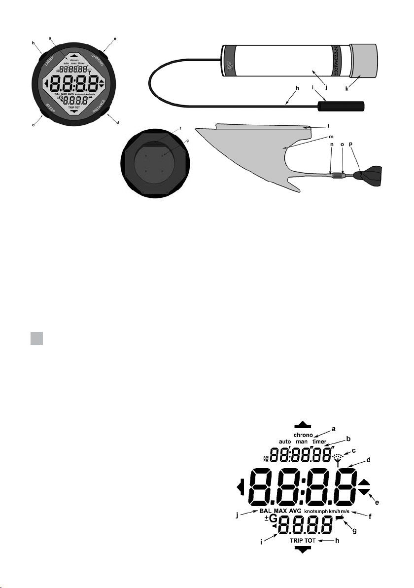
Display - front
Transmitter
Display - back
DISPLAY
a) LCD
b) Backlight button
c) Speed select button
d) Distance select button
e) Chronometer start button
TRANSMITTER
h) 0.3 m cable
i) Sensor for impeller
j) Transmitter body
k) Battery cap
IMPELLER
l) Mounting plate
m) Fin
n) Threaded shaft
o) Threaded base
p) Magnetized impeller
f) Spring snap for mounting plate
g) Battery cover (four screws)
2. Display Screen Descripon
a) Automatic (auto) or manual (man) chronometer, or countdown timer (timer)
b) Chronometer display, hours: minutes’ seconds”
c) Receiving transmission
d) Speed display
e) Speed increase or decrease
f) Units of measure (knots, mph, km/h, ou m/s)
g) Low battery indicator (for display)
h) Trip (TRIP) or total (TOT) distance
i) Distance display
j) Balanced (BAL), maximum (MAX), or average (AVG) speed
Impeller
2
Page 3
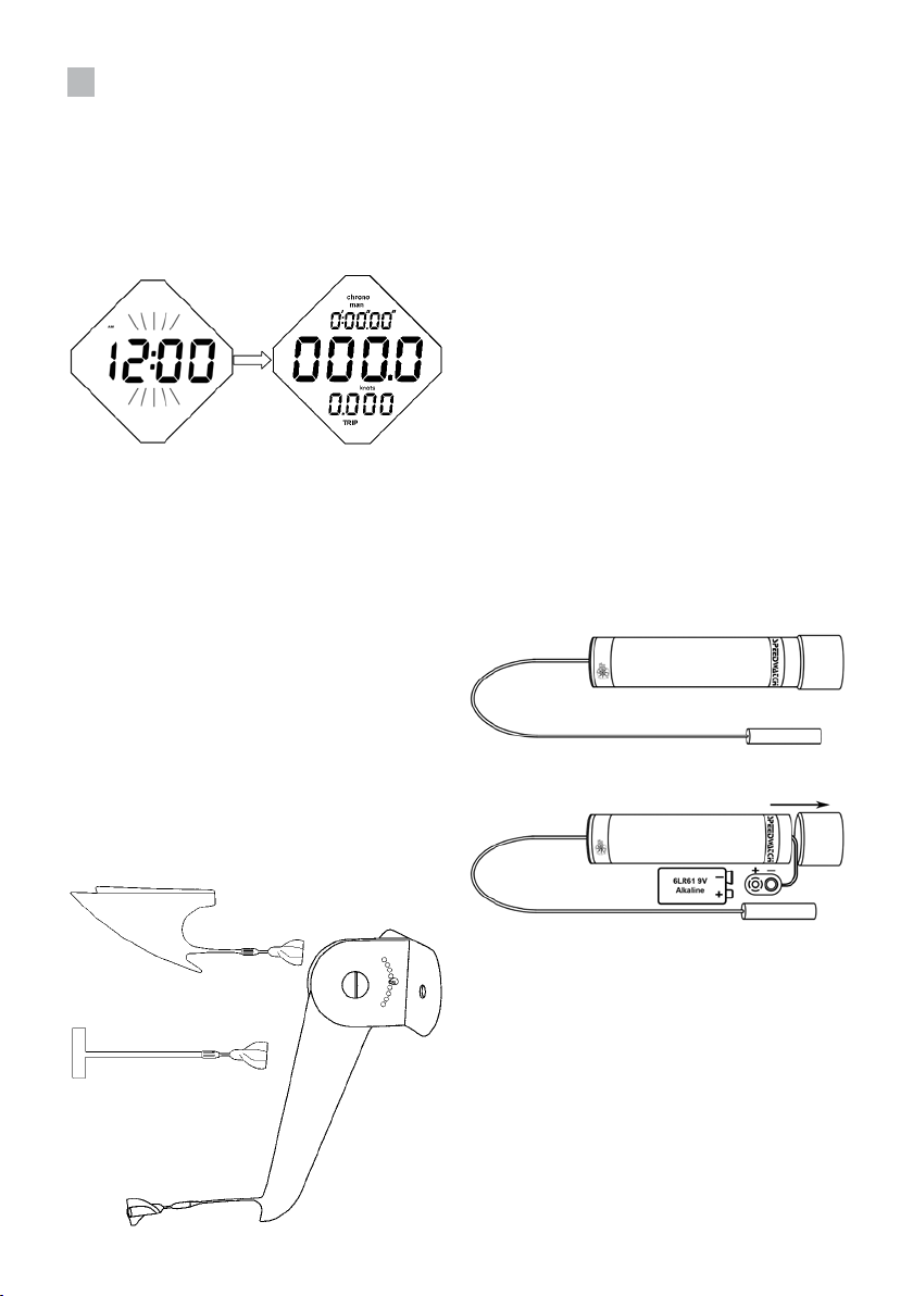
3. Start up the Instrument
DISPLAY
From the factory, the SPEEDWATCH is in a low
power state, with the time flashing. Press any
button to enter normal mode.
The SPEEDWATCH is now in Manual Mode;
it will only receive data from the transmitter
when the CHRONO button is pressed and the
impeller is rotating. The default speed is knnots,
which can be changed to mph, km/h, or m/s.
IMPELLER
The SPEEDWATCH impeller needs to be screwed
on to either the white fin mount (1), the large
black fin (2) or the rudder black fin mount
(3). The impeller is magnetized and creates a
magnetic pulse when rotating. This magnetic
pulse is received by the transmitter and
transmitted to the display. The display cannot
sense the impeller directly; the transmitter
must be on.
TRANSMITTER
The SPEEDWATCH Transmitter requires a 9V
battery to operate; this is included in your
system. To install the battery, gently pull the
cap exposing the battery compartment. Install
the 9V battery and replace the battery cap. Be
sure to press the cap back on fully to form the
water tight seal. Failure to do this could result
in the 9V battery failing. The electronics in
the SPEEDWATCH transmitter are completely
factory sealed. Do not attempt to open the case
exposing the electronics, or failure can occur.
It is not necessary to remove the battery except
for long period (winter storage) because the
power consumption is very low if no magnetic
field is received.
Red flashes appear on the bottom side when
the transmitter receives the magnetic signal
from the impeller.
1
2
3
3
Page 4

4. Programming the
SPEEDWATCH
Enter in the programming mode to set the:
- Chronometer – manual or automatic
- Countdown timer
- Speed unit
- Time
- Balanced speed duration
- Sensor claibration
To enter in the programming mode, you have
to be either in MANUAL chronometer mode
with stopped countdown timer or in automatic
and not read the signal.
Press and hold three seconds the both
SPEED and CHRONO buttons to enter in the
programming mode. “CHRONO” and “MAN”
(manual) or “AUTO” (automatic) will flash. Press
the DISTANCE or CHRONO buttons to change
settings, and on the SPEED button to confirm
the parameters and advance to the next item.
Press and hold the SPEED and CHORNO buttons
for three seconds to accept all parameters and
go back to the normal operating mode.
CHRONOMETER – MANUAL OR AUTOMATIC
Press the CHRONO or DISTANCE buttons to
alternate between the manual or automatic
chronometer. Press the SPEED button to confirm
the settings and advance.
SPEED UNIT
Press the CHRONO or DISTANCE buttons to
select the speed unit. It can be set in km/h
(kilometre per hour), m/s (meter per second),
knots or mph (miles per hour). Press the SPEED
button to confirm the settings and advance.
TIME SETTING
Press the CHRONO button to advance the time,
and the DISTANCE button to move the time
back. Press and hold the button to change the
time faster. It will start minute by minute for the
first ten minute change, then every ten minutes
for the next hour change, and then every hour.
The time is in AM/PM mode. Press the SPEED
button to confirm setting and advance.
BALANCED SPEED
The balanced speed setting averages the
instant speed over the selected time period to
provide a balanced speed reading. This can be
set from 2 seconds to 60 seconds, with varying
intervals (2, 3, 4, 5, 6, 8, 10, 12, 15, 20, 30, or 60
seconds). Press the CHRONO button to increase
the time, and the DISTANCE to decrease the
time. Press the SPEED button to confirm setting
and advance.
SPEDD SENSOR CLIBRATION
The SPEEDWATCH can be set to accept another
impeller, for example a style sensor “paddlewheel”.
The calibration for the SPEEDWATCH impeller is
40.0. The minimum value is 10.0, the maximum
value is 2000. Press and hold the CHRONO
button to increase or the DISTANCE button to
reduce faster the value. For other sensors than
the SPEEDWATCH sensor, you have to know
the setting for your impeller. Press the SPEED
button to confirm the settings and advance.
COUNTDOWN TIMER
Press the CHRONO or DISTANCE button to
select the countdown timer. It can be set to 10,
6, 5, 3 or 1 minutes. Press the SPEED button
to confirm the settings and advance. If the
countdown is changed, the SPEEDWATCH will
enter the countdown mode upon existing the
programming mode by pressing CHRONO and
SPEED.
4
The programming of the SPEEDWATCH is now
complete. Press and hold both the SPEED and
CHRONO buttons for three seconds to confirm
all settings and enter normal operating mode.
GENERAL RESET
Press the four buttons together to reset your
SPEEDWATCH.
Page 5

5. Basic Operang Mode
GENERAL BUTTONS USE
LIGHT Button: Turns on the backlight for 5
seconds (in any mode).
SPEED Button: Select the displayed speed in
bold character: instant, balanced, maximum or
trip average.
DISTANCE Button: Select the displayed distance,
trip or total.
CHRONO Button: Starts and stops the
chronometer and speed reading. Also starts
and pauses the countdown timer.
MEASURING SPEED AND DISTANCE
The SPEEDWATCH measures the actual speed
through water, not speed over land as with a
GPS. The small impeller is mounted under the
boat or kayak and generates a magnetic field
when rotating. This magnetic field is received by
the transmitter through the hull with no wires,
up to 30 centimeter. The transmitter sends out a
low frequency radio signal which is received up
to 5 meter by the display. To properly read speed
data, the impeller and transmitter should be
mounted properly. Please see the MOUNTING
section for detailed instructions. There are two
modes for measuring speed through the water,
MANUAL or AUTOMATIC. In MANUAL mode,
the timer is started and stopped by pressing the
CHRONO button. Speed is only measured and
registered when the timer is ON. In AUTOMATIC
mode, the timer starts when a signal is received
from the transmitter.
To reset the trip distance and the chronometer,
press the CHRONO button in manual mode
to pause the chronometer. Then, press and
hold the DISTANCE button. To reset the total
distance, press and hold 10 seconds the
DISTANCE button.
COUNTDOWN TIMER
The SPEEDWATCH can be set to provide a
countdown timer for the start of races. To
enter the programming mode, you must be
either in MANUAL chronometer mode with the
timer stopped or in automatic and reading any
signal (the timer will be stopped). Press and
hold both the SPEED and CHRONO buttons for
three seconds to enter the programming mode.
Press the SPEED button to advance to the timer
setting. Press the CHRONO or DISTANCE buttons
to select the countdown timer. This can be set
to 10, 6, 5, 3, or 1 minutes.
Press the SPEED and CHRONO buttons for
three seconds to exit the programming mode.
The time is displayed at the top of the LCD, the
countdown timer is displayed in the middle of
the screen.
Press the CHRONO button to start the
countdown timer. All other buttons are
disabled, except for the LIGHT button. Press
the CHRONO button to pause the countdown.
The timer will countdown, with a single beep at
each minute. At one minute left, a double beep
will sound each ten seconds. At ten seconds,
the SPEEDWATCH will beep three times each
second until 0:00. At 0:00 the signal will sound
for two full seconds. When the countdown
timer reaches 0:00, the SPEEDWATCH will
enter the normal operating mode, measuring
speed and distance. The chronometer is reset
to MANUAL, and can be paused by pressing
the CHRONO button. To cancel the countdown
timer, press the CHRONO button to pause the
countdown. Then press and hold the SPEED and
CHRONO buttons for three seconds to enter the
programming mode. Do not change the timer
setting; exit the programming mode by pressing
and holding the SPEED and CHRONO buttons
for three seconds.
5
Page 6

6. Mounng the
Speedwatch
IMPELLER
The impeller is fixed on the watercraft, with
many options. We recommend you to fixe the
impeller at the prow, to avoid turbulences.
TRANSMITTER
The transmitter is inside the hull with the
magnetic sensor at 30 centimeters from the
impeller. The transmitter has to be fixed with
the "Dual Lock" to avoid any movement.
DISPLAY
The display can be placed everywhere in the
boat until 5 meters from the transmitter. A
plastic mounting support is joined to the display
and can be mounting on a flat area or the Velcro
strap can be used to wrap around the mast or
the leg. The transmitter has to be fixed to avoid
movement but the display can be moved while
it receives data.
a) Impeller on fin attachement
b) Transmitter
c) Display (not to scale)
IMPELLER, TRANSMITTER AND DISPLAY
ORIANTATION
To have a maximum distance between the
impeller and the transmitter, we recommend
you to put the transmitter in perpendicular
position to the impeller as shown in the picture
below. The distance between the transmitter
and the display is maximum if the display is
perpendicular to the transmitter.
Three mounting systems are included in the
SPEEDWATCH kit; a removable fin mount, a
large fin to be fixed on the keel back side and a
rudder mount.
The rudder mount has a black clip that rests on
the edge of the rudder, the strips of adhesive
are then wrapped around the clip and secures
it to the rudder. The impeller is screwed onto
the end.
The large blade fin to be fixed on the keel back
side can either be attached with VHB adhesive
tape or by screws. The cotter pin can be moved
to adjust the movement of the fin to allow the
impeller to be out of the water.
The white fin mount has a base plate that
is attached to the hull, either with the VHB
adhesive tape or by screws. The fin can then
be inserted and removed to store the impeller
while not in use. The impeller is screwed onto
the end.
Transmitter
Impeller
Magnetic
sensor
Display
6
Page 7

IMPELLER MOUNTING OPTIONS
Small white fin mount:
Carefully clean the area before to stick the
adhesive and wait 24 hours before submersion
for best adhesion.
Rudder attachment:
Large blade fin mount:
7. Speed Sensor Calibra-
on
This operation allows the SPEEDWATCH to
be adjusted for an exceptional accuracy.
It’s normally not necessary. However, the
SPEEDWATCH can be calibrated with an existing
speed sensor to accuracy measure the speed.
Calibration is carried out from the programming
mode. Press and hold both the SPEED and
CHRONO buttons for three seconds to enter
the programming mode. “chrono” and “man”
(manual) or “auto” (automatic) will flash. Press
the SPEED button five times to advance to the
calibration mode. The proper calibration is 40.0
for the SPEEDWATCH impeller. To adjust the
SPEEDWATCH, increase this number (CHRONO
button) to decrease the speed reading. Decrease
this number (DISTANCE button) to increase
the speed reading. The displayed number
corresponds to the distance in mm done by one
turn of the impeller or the circumference of the
wheel. Press and hold the SPEED and CHRONO
buttons for 3 seconds to accept all settings and
go back to the normal operating mode.
7
Page 8

8. Technical Specicaons
IMPELLER TRANSMISSION
The impellers, fixed on synthetic sapphire
bearings, are equipped with powerful magnets
that generate magnetic impulses. These
impulses are collected by coils (also called
“sensor”) and treated electronically to be
display speed. The magnetic impulses can
go through any materials: fibreglass, carbon
fibre, aramid fibre, wood, plastic, aluminium,
stainless steel, etc. It is why you do not need to
pierce the hull. This system is very sensitive; it
can display a value near an electrical motor or
an electrical light, even if the impeller does not
turn. This is completely normal and does not
affect the reading when the impeller turns.
TRANSMITTER RANGE
The SPEEDWATCH transmitter operates on a
low-frequency (8 kHz) which is wireless display.
Many screens can be used for one transmitter.
The range is ruled to provide the maximum
distance in the watercraft but it cannot create
an interference with other nearby system.
ACCURACY
Tests were made at the Bremen University
(Germany) in hydraulic canals. The results
clearly showed that the SPEEDWATCH is in LDA
(Laser Doppler Anemometry) 3% accuracy.
SPIN OUT
All water tests made in real situatione with high
speed windsurfs (more than 30 knots) showed
that there were no turbulences from the T
attachment which hold the fin. Information
transmitted by major European windsurf
manufacturers.
TRAIL
The impeller trail is 40 grams at 10 knots.
Measurements were made in hydraulic canals
in Bremen University in Germany.
9. Limite Warranty
JDC ELECTRONIC SA extends a 12 months’ warranty over parts and labour for this instrument,
effective from the date of purchase. JDC ELECTRONIC SA reserves the right to repair or replace any
component which may have become faulty in the course of normal use. This repair or replacement
shall be carried out at no charge to the customer (parts or labour). Transport costs however shall
be borne by the customer. This warranty does not cover damages caused by an accident, abnormal
or excessive use, or resulting from an unauthorised modification or repair.
For international warranty support, contact your dealer.
Developed and manufactured by:
JDC ELECTRONIC SA
Avenue des Sports 42, 1400 Yverdon-les-Bains,
Switzerland
Phone: ++41 (24) 445 2121
Fax: ++41 (24) 445 2123
e-mail: info@jdc.ch
Internet: www.jdc.ch
 Loading...