

Page 1
Operating manual
www.jdc.ch
JDC ELECTRONIC SA
Avenue des Sports 42
CH-1400 Yverdon
Switzerland
www.jdc.ch
info@jdc.ch
P: +41 24 445 21 21
F: +41 24 445 21 23
Page 2

2
Page 3

Index
English
GB
Introduction
Items included .......................................................................4
Warranty ...............................................................................4
General description of operation ..............................................5
Meteorological measurements .................................................5
Recording measurements .......................................................5
Clock and synchronization .......................................................5
Technical Specications
General data ..........................................................................6
Meteorological transmitter ......................................................6
SKYWATCH AEROlog software
Installation of the software .....................................................8
USB driver .............................................................................8
Connecting to the station ........................................................8
Measurement parameters .......................................................9
Measurements .......................................................................9
Date and Time .......................................................................9
Units .....................................................................................9
Memory ...............................................................................10
Localization .........................................................................10
Real time viewing .................................................................10
Viewing of recorded measurements ....................................... 11
Installation guide
Step 1 - Fitting transmitter ....................................................12
Step 2 - Installing transmitter ...............................................12
Step 3 - Station orientation ...................................................13
Step 4 - Fixing remote box....................................................13
Step 5 - Wiring up remote box .............................................. 14
Step 6 - Station states ..........................................................14
Technical assistance
Contact ...............................................................................15
3
Page 4
Introduction
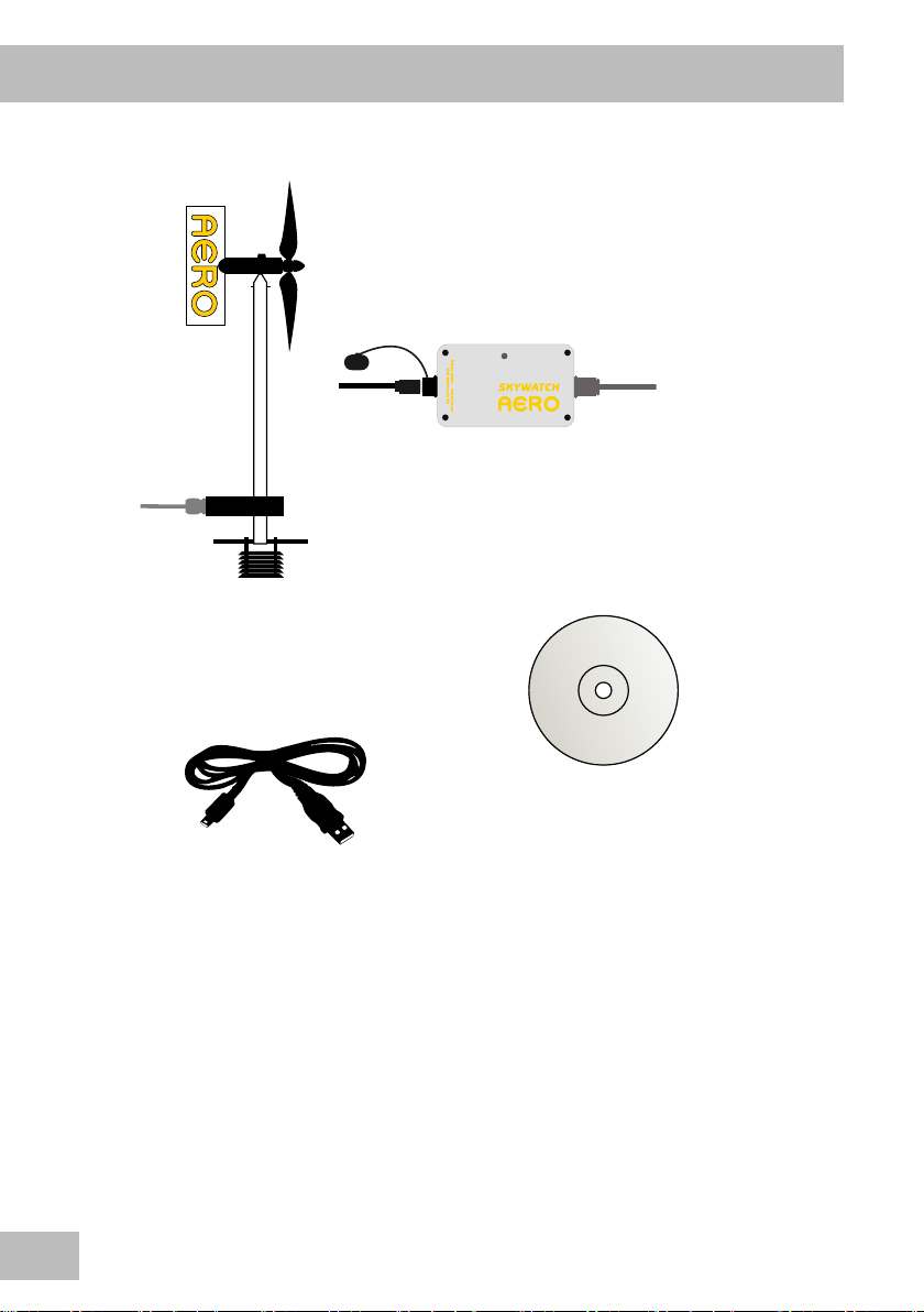
Items included
1x mini USB cable
1 x transmitter
with remote box
1 x AEROlog SKYWATCH CD
Warranty
Your SKYWATCH® AERO is guaranteed by JDC ELECTRONIC SA for one year starting
on the date of purchase in respect of all defects of manufacture. The warranty does not
cover damage caused by incorrect use. JDC ELECTRONIC SA cannot be held responsible
in any case for any consequences, direct or indirect, nor for any damage that may result
from the use of this instrument or from any fault or breakdown in it.
4
Page 5

General description of operation
This meteorological station can measure the following parameters:
• Maximum, minimum and average windspeeds
• Maximum, minimum and average wind directions (as an option)
• Temperature and humidity (as an option)
• Pressure (as an option)
The station, powered by two LR6 batteries, can be easily installed at isolated sites and
in extreme conditions.
The starting and stopping of the measurement process can be done via the SKYWATCH
AEROlog software using the button to be found in the remote control box.
An LED on the control box indicates the system status. Its ashing indicates that the
system is taking measurements.
Meteorological measurements
The SKYWATCH AERO station takes windspeed and direction (as an option) measurements
every second. Temperature, humidity and pressure (as options) are measured once per
cycle. The time for calculating the average is adjustable using the SKYWATCH AEROlog
software.
Recording measurements
All measurements are saved in the station memory. They can be downloaded to a PC
using the USB port and then automatically saved in a CSV le.
GB
Clock and synchronization
The station has an internal clock that allows measurements to be time stamped.
5
Page 6
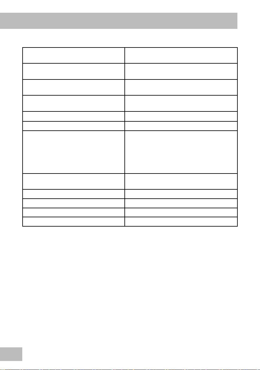
Technical Specications
General data:
Dimensions (L x H x D) Housing: 64x110x38 mm
Transmitter: 160x410x200 mm
Weight Housing: 400g
Transmitter: 550g
Protection class Housing: IP 65
Transmitter: IP 67
Materials Housing: aluminum
Transmitter: stainless steel
Power Supply 2 batteries LR6
Battery autonomy More than one year
Measuring channels
(all options)
Recording More than 600,000 time stamped
Clock Internal
Communication connector Mini USB
Operating temperature Measurement and recording: -30 … +80 °C
Cable length 5m, other lengths on request
Average wind direction
Average windspeed
Maximum windspeed
Air temperature
Air relative humidity
Atmospheric pressure
measurements in non-volatile memory
6
Page 7
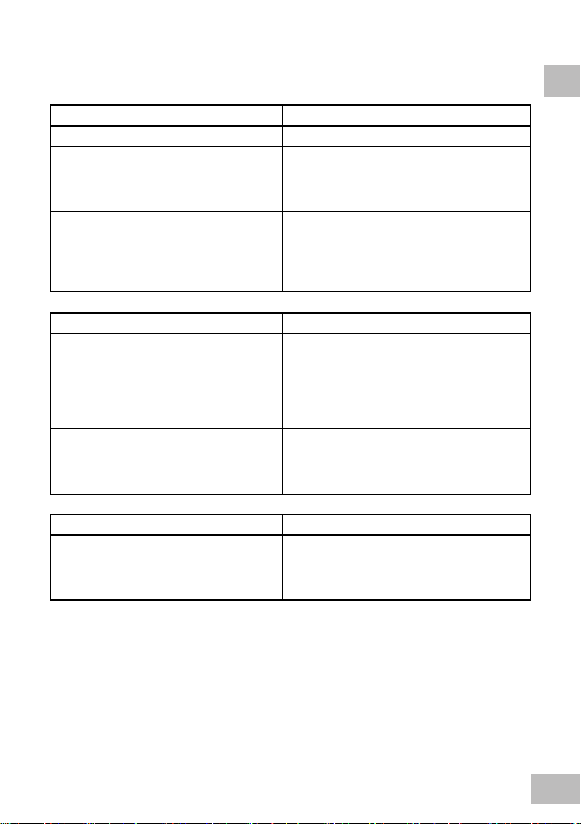
Meteorological transmitter:
Wind (direction as an option)
Sampling 1 measurement per second
Average wind direction
Measuring range
Precision
Resolution
Average and maximum windspeed
Measuring range
Precision
Resolution
Units
Temperature and humidity (as an option)
Air temperature
Measuring range
Precision
Resolution
Units
Air relative humidity
Measuring range
Precision
Resolution
0 … 360°
± 5°
1°
3 … 200 km/h
± 3%
0.1 km/h
km/h, m/s, mph, fps, knots
-40 … +90 °C
± 0.6 °C (0 .. +50 °C)
± 1.5 °C (-40 .. +90 °C)
0.1 °C
°C, °F, K
0 … 100 %RH
± 1.8 %RH (10 .. 90 %RH)
0.1 %RH
GB
Barometric pressure (option)
Measuring range
Absolute precision
Resolution
Units
10 … 1100 mbar
± 1.5 mbar (750 ... 1100 mbar)
0.1 mbar
hPa, Pa, bar, atm, psi, mmHg
7
Page 8

SKYWATCH AEROlog software
SKYWATCH AEROlog software was developed as a user interface for conguration,
viewing measurements in real time and downloading of measurements recorded by the
station.
Installation of the software
If the computer is connected to the internet, double-clicking on the “setup.exe” le under
“AEROlog” on the CD initiates software installation. In the rst instance the installer
proceeds to analyse whether the PC has the necessary prerequisites for software use;
otherwise, the “.net” framework will be updated.
If the computer is not connected to the internet, the “.net” framework must rst be
installed by double-clicking on the “dotNet…exe” le in the “AEROlog” directory on the
CD.
USB driver
When the AERO station is connected to the PC by USB cable, a new virtual serial port
is installed on the computer. If needed, the driver is available on the CD in the “Driver”
directory. Before installing the driver, make sure you disconnect the station USB cable.
Connecting to the station
Once the SKYWATCH AEROlog software is installed, the
rst step is to connect up to the AERO station: click
on “Connect” menu, then choose between “Auto” and
“Manual”.
The “Auto” mode scans all USB ports and connects up
to the rst station it nds. The “Manual” mode allows
the user to choose which port is to be connected to.
This mode is used particularly when several stations
are connected to the same PC. The desired port has
to be selected from a pull-down list, then click on the
“Connect” button. The port selected will be saved to
memory.
When the station is connected, the “Connected” status is displayed on a green background
in the menu bar.
Click on “Disconnect” in the “Connect” menu to disconnect.
8
Page 9
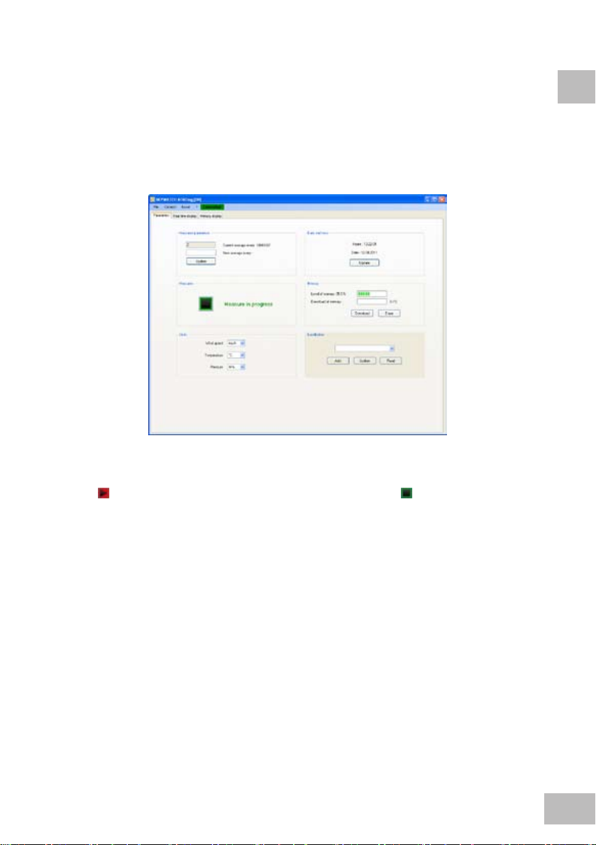
Measurement parameters
The station takes a wind measurement every second. The duration in seconds on which
the average is to be calculated has to be dened. This interval can be changed by entering
the desired value to the eld set up for this. When the new average is indicated to you,
press on “Update” to transmit the information to the station. The other parameters
(temperature, humidity, pressure) are measured once per interval.
Measurements
GB
Click on button to start the measurement process. Press on button to stop it. If the
station is deleting memory, it is not possible to start the measurement process.
When the measurement process is activated, the LED ashes for 3 seconds, then ashes
once every three seconds. When the measurement process is complete, the LED ashes
again for 3 seconds before going out.
Date and Time
The software displays the station time. To update this time in relation to the PC, press
on “Update” button.
Please note that the changing non DST / DST is not automatically done by the station.
Units
The user can choose in which unit the measured values should be displayed. The units
selected are used for real-time display and for saving the measurements in the CSV le.
These units are saved in memory.
9
Page 10

Memory
This is the station memory. The memory level indicates the percentage of the memory
used by the measurements. The measurements can be changed and saved in a CSV le.
Afterwards the memory can be deleted.
Localization
The user can dene a station position so as to differentiate
between the stations. This information will be recorded during
downloading to the CSV le. To assign a location to a station,
select the latter from the list set up by the user, then press
“Update”.
To add a location to the list, press on “Add”. The “Localization”
window opens. Enter the new location in the eld prepared for
this then press on “Add”.
To delete a location from the list, select the location and press
on “Remove”.
Real time viewing
When the measurement process is active, the user can view the readings in real time in
the “Real time display” tab. Readings along with a graphic for each of the parameters
are then available for viewing.
10
Page 11
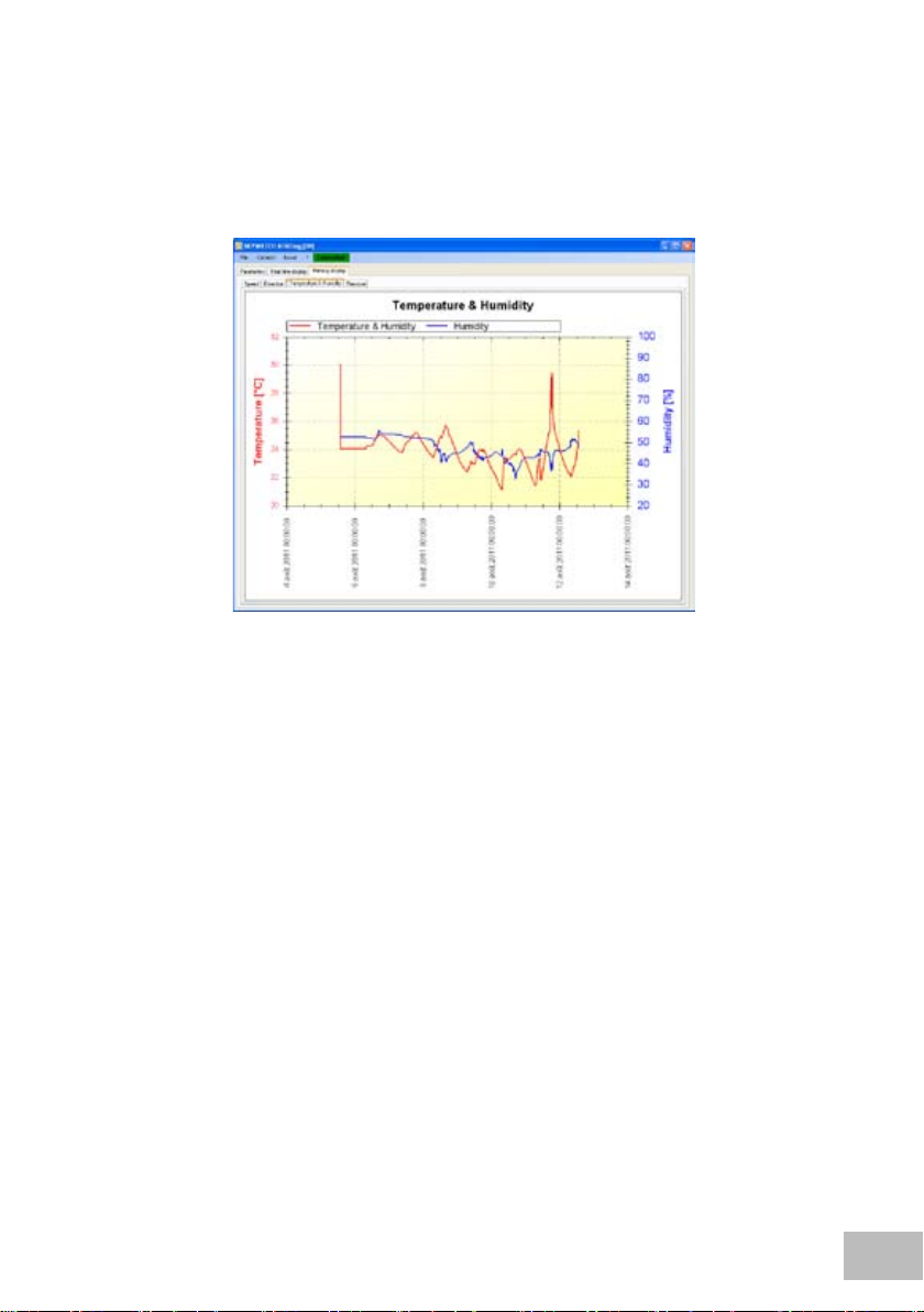
Viewing of recorded measurements
Following station memory downloading, the user can view the graphic of each of the
parameters saved in the memory.
11
Page 12

Rear blade cutting edge
Installation guide
1
1
2
1
2
3
Step 1 - Fitting transmitter
Place blades horizontally, then rmly
screw in propeller nose to lock the
blades.
Place propeller with its axis
vertical and lock it in the throat
using 2.3mm circlips and at
pliers.
Retighten metal plug.
Fit anti-radiation shade to the transmitter
lower part. Gently push in shade until
tube touches anti-radiation shade
protection grid
12
Mast
Fixing arms
Step 2 - Installing transmitter
The transmitter should be placed as far as possible from any obstacles
that could disturb air ow, such as the roof of a house, for example.
Ideally the transmitter should be xed on a horizontal arm using two
holes M4 or four holes 5.5mm dia, and the arm then xed to a mast.
Page 13

Step 3 - Station orientation
The arm to which the transmitter is xed should be oriented so that the cable
exit points to the west.
N
GB
W
View from above
Step 4 - Fixing remote box
The remote box is totally watertight. Therefore it can be located
outside.
It is advisable to x the remote box, for example to the mast.
E
S
13
Page 14

Step 5 - Wiring up remote box (as an option)
This operation is reserved for personnel who have a basic knowledge of
electricity. The cable of the remote box can be removed so as to shorten it or
to pass it through a hole.
Batteries must be removed before changing the cable.
To carry out such a modication, take out the leads by unscrewing them from
the terminal box and then, following modication of the length or passage of
the cable through a hole, reconnect leads in the following order:
• Terminal n°1
• Terminal n°2 brown
• Terminal n°3 green
• Terminal n°4 yellow
• Terminal n°5 grey
• Terminal n°6 pink
• Terminal n°7 blue
This modication causes the lost of the product warranty.
white + screening
Step 6 - Station states
The remote box has a red LED that gives information on the station condition:
14
LED condition Measurements Battery level
No light Stopped Good
Flashing once every 3 seconds Running Good
Flashing twice every 10 seconds Running Medium
Flashing 3 times every 30 seconds Stopped Low
Page 15
Technical assistance
www.jdc.ch
Contact
If there is a problem and for all technical questions, please contact us directly:
E-mail: support@jdc.ch
Telephone: +41 24 445 21 21
Fax: +41 24 445 21 23
GB
15
 Loading...