

Page 1
Page 2
English
How to use this Manual
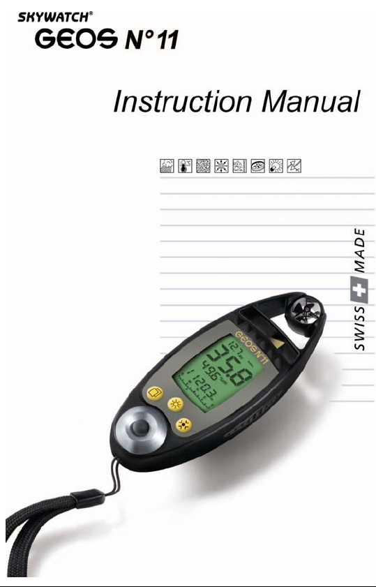
We thank you for selecting a SKYWATCH® instrument .
Even though this instrument was designed for ease of use in mind, we
recommend that you nonetheless spend a little time reading this Manual
in order to be able to use it to its full potential.
Where to find information
All the headlines and sub-headlines are regrouped under the ‘Table of
Contents’. Throughout the Manual, you will discover special symbols
which will bring to your attention important aspects, general information
and warnings. The diagrams showing some of the screens are also aimed
at helping you fully understand how the instrument operates.
Symbols used in this Manual
Remark or additional information
The instrument may be damaged or not work adequately if this
instruction is not heeded.
Warnings point out the precautionary measures to be taken in
order to avoid some undesirable situations.
2
Page 3

Table of Contents
How to use this Manual......................................... 2
Where to find information.......................................................2
Symbols used in this Manual .................................................2
Table of Contents................................................3-5
Introduction............................................................ 6
Background information.........................................................6
WARNING .................................................................................6
Description of Instrument ......................................................7
Functions (Measuring Modes)................................................7
Description of the Sections of the Display Screen ..............8
Display principle with regard to functions..............................8
Distribution of basic modes over the standard screen....... 8-9
Starting up the Instrument.................................... 9
First Use (out of factory)................................................... 9-10
Instantaneous State...............................................................10
Normal State (on)...................................................................10
Switching the Instrument off .........................10-11
Basic Measuring Mode (Standard Screen)........ 11
General Use of Buttons.........................................................11
Wind speed.............................................................................12
Measuring modes................................................................12
Resetting the maximum wind speed to zero........................12
Selecting the unit of measurement......................................12
Temperature...........................................................................12
Measuring modes.......................................................... 12-13
Selecting the unit of measurement......................................13
Resetting the minimum and maximum values to zero.........13
Humidity .................................................................................13
Measuring modes................................................................13
Resetting the minimum and maximum humidity to zero......14
Pressure .................................................................................14
Measuring modes................................................................14
Selecting the unit of measurement in relation to altitude.....14
Calibration of the altitude............................................... 14-15
Resetting the maximum altitude and the QFE height..........15
3
Page 4

Selecting the unit of measurement in relation to pressure ..15
Calibration of relative pressure (QNH) .......................... 15-16
QFE height...........................................................................16
Resetting the Maximum Altitude and the QFE Height.........16
Calibration of QFE pressure................................................17
Compass.................................................................................17
Display........................................................................... 17-18
Calibration............................................................................18
Flight Level.............................................................................19
Display.................................................................................19
Special Screens.................................................... 19
Special Measuring Modes.....................................................19
Special Menu..........................................................................19
Display........................................................................... 19-20
Enabling a Special Mode.....................................................20
Date and Time........................................................................21
Display.................................................................................21
Operation.............................................................................21
Calibration............................................................................21
Barometric Tendency............................................................21
Display.................................................................................21
Operation....................................................................... 21-23
Chronometer ..........................................................................23
Display.................................................................................23
Operation.............................................................................24
Density Altitude .....................................................................24
Display.................................................................................24
Operation.............................................................................24
Magnetic Field in µTesla + Compass Heading....................25
Display.................................................................................25
Operation.............................................................................25
Calibration............................................................................25
Magnetic declination...................................................... 25-26
Variometer..............................................................................26
Display.................................................................................26
Operation.............................................................................26
Finesse ...................................................................................26
Display.................................................................................26
Operation.............................................................................27
Memories, Viewing and Settings........................ 27
4
Page 5

Manual Recordings................................................................27
Display.................................................................................27
Operation.............................................................................28
Viewing................................................................................28
Measurements Based on Selected Rate..............................29
Display.................................................................................29
Operation.............................................................................29
Viewing................................................................................29
Selecting the rate of recordings...........................................29
History ....................................................................................30
Display.................................................................................30
Operation.............................................................................30
Viewing and rate selection...................................................30
Other...................................................................... 30
States of the Instrument........................................................30
Storage................................................................................31
OFF......................................................................................31
Automatic Stop .............................................................. 31-32
Permanent operation...........................................................32
Data transfer to a PC...........................................................32
Other states.........................................................................33
Resets.....................................................................................33
Memory reset (deletion).......................................................33
Screens reset.......................................................................33
General reset................................................................. 33-34
Instrument reset...................................................................34
Power Supply, Battery Replacement...................................34
Batteries fitted in the instrument.................................... 34-35
Batteries of the Light Emitting Diode (LED )Lamp...............35
Condition of the instrument battery................................ 35-36
LCD Display Test...................................................................36
Temperature Compensated Quartz......................................36
Calibration of the Pressure Sensor......................................37
Technical Specifications................................37-38
LIMITED WARRANTY ............................................................39
5
Page 6

Introduction
Background information
The GEOS N°11 is a high performance instrument used by professionals,
the culmination of our 25 years of experience in the development and
manufacturing of measuring devices. It is solely built with industrialquality components and uses Swiss-made barometric pressure, wind
speed, humidity, and temperature sensors.
The instrument is put together with great care in our Swiss
manufacturing facility, where sensor accuracy is controlled using our
quality-certified laboratory equipment.
The GEOS N°11 is specially designed for intensive use in extremely
harsh conditions. Yet, in order to maintain its aspect and accuracy, we
recommend that you treat it with care and that you read this Manual
carefully.
WARNING
This instrument is designed as an aid to users who are in an open air
environment, but IT CANNOT replace advice and warnings from the
local weather station. This means that you should regularly check and
compare the measurements provided by your instrument with the
information put out by the weather station.
Open-air climatic conditions can sometimes change quite dramatically
and this can happen very quickly indeed. Sunny weather can, for
example, change to thunderstorm conditions in the space of half an hour
and sometimes less. You should therefore always follow basic safety
rules whenever you undertake open air activity.
Under no circumstances shall JDC ELECTRONIC SA be held liable for
any consequence, be it direct or indirect, and for any damage that may
occur as a result of using this instrument.
6
Page 7
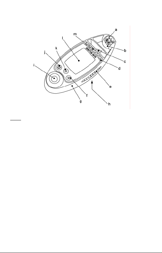
Description of Instrument
Legend
a wind sensor (impeller) h lid of battery compartment
b protective sphere around the impeller i light emitting diode (L D) lamp E
c weather vane j selection (SEL) button
d black metal case k luminosity (LUM) button
e ribbed rubber strip l mineral glass window
f modification OD) button m protection slots for the sensors (M
g plastic frame
Functions (Measuring Modes)
Wind speed:
- instantaneous
- average
- maximum
Temperature :
- instantaneous
- minimum
- maximum
- windchill
- minimum windchill
- maximum windchill
Humidity:
- current relative
- minimum relative
- maximum relative
- Dew point:
Pressure:
- absolute
- relative pressure (QNH)
- ground pressure (QFE)
- altitude
- maximum altitude
- density altitude
- QFE height
- flight level
- finesse
- variometer
- barometric tendency
Compass (magnetic or true
North):
- analogue
- digital
Clock:
- date, time
- chronometer
Other:
- battery voltage check
- diode lamp
7
Page 8
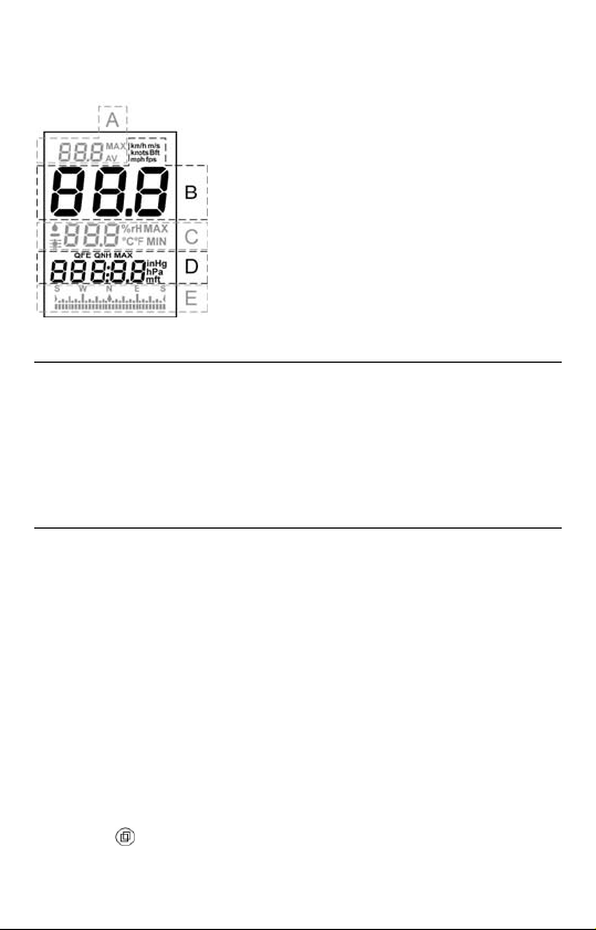
Description of the Sections of the
Display Screen
A
B
C
D
E
Display principle with regard to functions (measuring modes)
Each measuring mode occupies a very particular space on the screen.
Measuring modes are always displayed following the same principles, i.e.:
- 1 standard screen containing all the basic measuring modes.
- 1 screen per special mode, when activated.
- 1 'special menu' used to enable/disable the special modes, view
memories and carry out some adjustments.
Distribution of basic modes over the standard screen
Each block (with the exception of the large one), accommodates several
measuring modes; however, only one mode may be displayed at the
same time per block. The basic measuring modes are displayed on the
standard screen as follows:
upper block: average and maximum wind speed
large block : instantaneous wind speed
middle block: all the temperature and humidity measuring modes,
including dew point
lower block: digital compass and all the functions relating to
pressure, including altitude, flight level, and height
compass block: analogue compass (1 mark located under the bargraph
indicates the heading)
The SEL ( ) button is used to select a block (the block flashes when
selected). The selection time (flashing) is 5 seconds. Each time the
Upper block
Large block
Middle block
Lower block
Analogue compass block
8
Page 9
button is pressed briefly, the next block is selected in the following order:
upper, large, middle, lower, upper, etc. If one (or several) special mode
has (have) been activated, the selection will take place as follows: upper,
large, middle, lower, special mode screen, upper, etc.
The MOD ( ) button is used to modify the display of a block (it scrolls
down the various modes of the block), and will only work if the block is
selected.
Remark: The last mode displayed on a block becomes the default
mode for this block, which means that if the instrument is switched
off than turned back on, the standard screen configuration will be
the same as the configuration displayed before it was switched off.
Starting up the Instrument
First Use (out of factory)
When fresh out of the production line, the instrument is supplied in a
storage state, i.e. with all the sensors disabled, including the internal
clock. This state allows the storage of the instrument for a long period
of time without running the battery down.
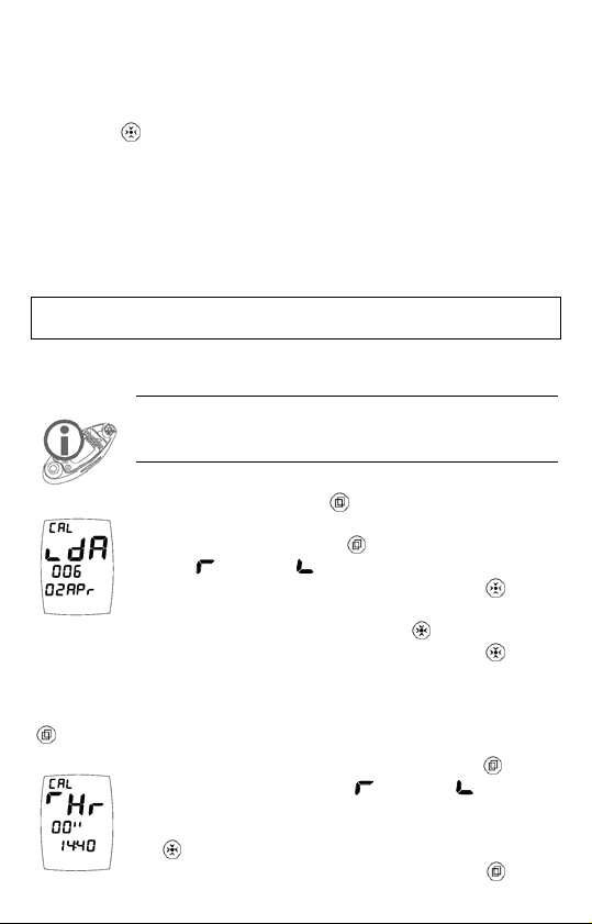
Press and keep down the
activates the instrument which asks you to set the date.
Select by pressing briefly the
setting (
format (02Apr or Apr02). Pressing briefly of the
will scroll the days 02Apr, 03Apr, 04Apr…..30Apr,
01May, etc. To increase scrolling speed, keep the
switch to an even greater scrolling speed, release then keep the
down again, etc. (4 speed levels). The year (displayed with 3 digits, here
006 = 2006) cannot be set individually, but changes automatically when
passing from December 31st to January 1st. Once the date is set, keep the
button down to confirm your settings.
You are now about to set the time. With the button
select the scrolling direction (
and the time format (A for AM and P for PM, or 24:00
format). Setting the time is also achieved with the help of
the
(please see above). Once the time is set, keep the
increment, decrement) as well as the display
button, and in the same way as with the date setting
button, then release it; this
button the direction of the
button down, to
increment, decrement)
9
button
button
button
Page 10
down to confirm your setting, the instrument is than activated and
displays the standard screen.
Remark: Setting the date and time may also be carried out at a later
stage. Please refer to Section on ‘Special Modes’; ‘Date and Time’.
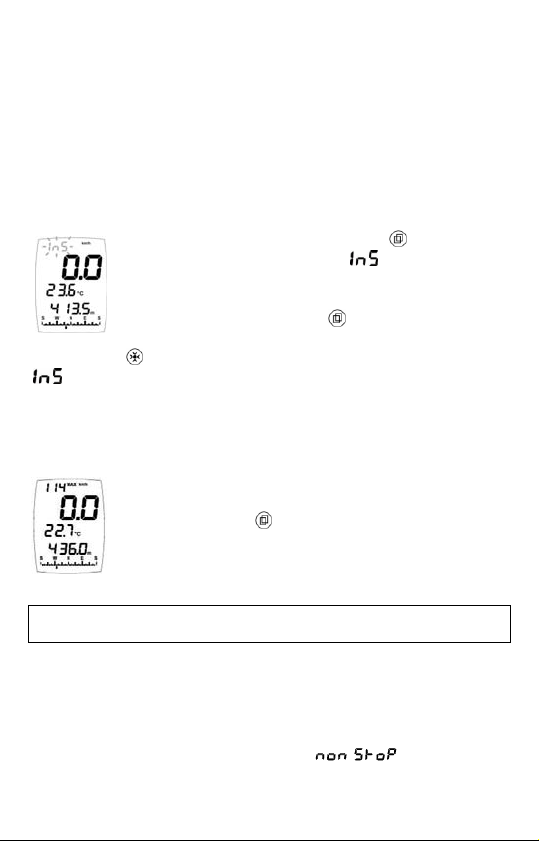
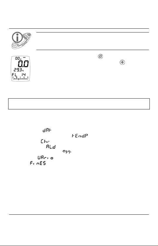
Instantaneous State
(The instrument remains turned on for only 5 seconds)
This state allows you to see the current measured values at a glance,
while saving the battery.
When the instrument is off, pressing the
lights up the instrument, while the
meaning instantaneous, flashes on the upper block (see
opposite). The instrument displays the default screen.
A second brief pressure on the button displays the date
(analogous day, month, hours, and seconds). By pressing
briefly on the
, and the year instead o f the time.
With the third push of the button or after 5 seconds, the instrument turns
off.
button, the day of the week can be displayed instead of
button briefly
message displayed,
Normal State (on)
When the instrument is in the OFF or instantaneous state,
keep pressing the
instrument displays the default screen.
button down for 2 seconds. The
Switching the Instrument off
In order to manually turn off the instrument, keep any of the buttons
down for 3 seconds; the stop screen is displayed and a countdown takes
place on the large block: 3, 2, 1, 0, followed by the deactivation of the
instrument. The middle block indicates the time before the automatic stop
(new parameters may be entered, as shown under Section ‘Other’;
‘Automatic stop’). On the other hand, the
that the instrument is in the permanent operating state. Following a
manual stop, the instrument sets itself back by default in the auto-stop
10
message means
Page 11
state. Releasing the button during the countdown, brings back the default
screen on the instrument.
Basic Measuring Mode
(Standard Screen)
Reminder: All the basic modes that are described hereafter are
available on the same screen ( standard screen), only the special
modes avail of a screen per mode (see relevant section).
The last measuring mode displayed on a block becomes the default
mode for this block; when you turn your instrument off and back on
again (instantaneous and normal states), the configuration of your
standard screen will be the same as that displayed when the instrument
was turned off.
General Use of Buttons
SELection Button: a brief push of the button selects a block of the
standard screen or a special screen, the block flashes when it is
selected (the selection/flashing time is 5 seconds). When settings
are entered or when looking at data, pressing it briefly makes it
possible to change the direction of the adjustment. As a rule,
pressing the button for 2 seconds will bring the standard screen
back up, allow to terminate a calibration, or exit the special menu.
By pressing it for a long time (3 seconds) in a flashing state it is
possible to access the settings of a number of values. If the
standard screen is normal (not flashing), pressing the button for a
long time will turn off the instrument.
LUMminosity Button: a brief push of the button switches on the
backlighting for 5 seconds, or turns it off if it is already on.
Pressing the button for 1 second turns on the backlighting for a
duration of 20 seconds. Activating a button when the backlighting
is on, keeps it on for another 20 seconds, this in order to stop it
from switching off while performing an adjustment for instance.
Pressing the button for a long time turns off the instrument.
MODification Button: a brief push of the button changes the
display of the selected block and gives access to the memories.
Pressing the button for a long time makes it possible to change the
unit of measurement of the selected block and reset certain values.
Pressing the button for a long time turns off the instrument.
11
Page 12
Wind speed
Measuring modes
Instantaneous wind speed Maximum wind speed Average wind speed
The measuring modes for the maximum and average wind speeds are
displayed on the upper block, while the instantaneous wind speed is
displayed on the large block. In order to access the measuring mode for
the maximum reached or average wind speed, select (with the help of the
button) the upper block (it flashes), then use the button to modify
the block display and switch from one measuring mode to another.
Resetting the maximum wind speed to zero
Select the upper block and display the measuring mode for the maximum
wind speed (it flashes), then press the
button for 2 seconds.
Selecting the unit of measurement
The instrument features 6 units of measurement in relation to wind
speed: km/h (kilometres per hour), mph (miles per hour), knots, m/s
(metres per second), fps (feet per second) and Beaufort (Beaufort scale).
To change the unit of measurement, select the large block (it flashes),
then keep the
button to confirm your choice.
button down; when the desired unit appears, release the
Temperature
Measuring modes
Ambient
temperature
Minimum
temperature
Maximum
temperature
Instantaneous
windchill
temperature
12
Minimum
windchill
temperature
Maximum
windchill
temperature
Page 13

The various measuring modes in relation to temperature are displayed on
the middle block. In order to access a measuring mode, select (with the
help of the
button) the middle block (it flashes), then use the
button to change the display on the block and switch from one measuring
mode to another.
Selecting the unit of measurement
The instrument features 2 units of measurement in relation to temperature:
°C (degrees Celsius) and °F (degrees Fahrenheit)
To change the unit of measurement, select the middle block and display
the measuring mode in relation to temperature (it flashes), then keep the
button pushed down; when the desired unit is displayed, release the
button to confirm your choice.
Resetting the minimum and maximum values to zero
Select the middle block and display the measuring mode that you wish to
reset (it flashes), then press the
button for 2 seconds.
Humidity
Measuring modes
Relative humidity Minimum humidity Maximum humidity Dew point
The dew point of air is the temperature at which, while keeping the current
barometric conditions as they are, the air becomes saturated with water
vapour. It is the phenomenon of condensation which occurs when the dew
point is reached that creates the clouds, mist and dew.
The various measuring modes in relation to humidity (including the dew
point) are displayed on the middle block. In order to access a measuring
mode, select (with the help of the
then use the
button to change the display on the block and switch
from one measuring mode to another.
button) the middle block (it flashes),
13
Page 14

Resetting the minimum and maximum humidity to zero
Select the middle block and display the measuring mode that you wish to
reset (it flashes), then press the
button for 2 seconds.
Pressure
Measuring modes
altitude altitude pressure height pressure flight level
maximum relative (QNH) QFE absolute
The various measuring modes in relation to pressure are displayed on the
lower block. In order to access a measuring mode, select (with the help
of the
button) the lower block (it flashes), then use the button to
change the display on the block and switch from one measuring mode to
another.
Selecting the unit of measurement in relation to altitude
The instrument features 2 units of measurement in relation to altitude:
m (metres) and ft (feet).
To change the unit of measurement, select the lower block (it flashes),
then keep the
button to confirm your choice.
button down; when the desired unit appears, release the
Calibration of the altitude
The instrument calculates altitude by using air pressure. It is
therefore quite normal for the altitude to change when the air
pressure changes. For this reason the instrument needs to be
calibrated as often as possible.
Stabilization of the altitude: each time it is turned on, the instrument
carries out an automatic calibration based on the drift of the weather
driven trend, this in order to avoid displaying an altitude that is too far
off. This calibration does not occur when the data is accessed
instantaneously.
14
Page 15

Select the lower block and display the measuring mode in
relation to altitude (it flashes), then keep pushing the
button down.
starts flashing on the upper block. Release
the button as soon as you enter the calibration function
(screen opposite). Use the button to select which way the
setting is made (
value of the altitude using the
the value in increments of 0.1 unit. Keep the
increments of one unit. Release then press the
increment, decrement), then set the
button. Pressing briefly on the button sets
button down to set
button again for a faster
setting. Repeat a second time the “release/keep down” operation to obtain
increments of 10 units and repeat a third time if you wish the setting to go
in 100-unit increments. Confirm and exit the calibration by keeping the
button down; the instrument goes back to the standard screen. Remark:
Setting the altitude is limited to the plausible range with regard to the
pressure currently being measured.
If you do not know your altitude, you can find it by calibrating the QNH
pressure, provided you know the latter exactly.
Resetting the maximum altitude and the QFE height
Select the lower block and display the measuring mode that you wish to
reset (it flashes), then press the
button for 2 seconds.
Selecting the unit of measurement in relation to pressure
The instrument features 2 units of measurement in relation to pressure,
with the choice between:
hPa (hectopascals, equivalent to the millibar) and inHg (inches of
Mercury).
To change the unit of measurement, select the lower block (it flashes),
then keep the
button to confirm your choice.
Calibration of relative pressure (QNH).
button down; when the desired unit appears, release the
The relative atmospheric pressure is a value that is calculated at sea
level on the basis of the local absolute pressure. As a result, it is taken
as a reference to assess the atmospheric conditions and the evolution
of weather throughout the country. This is the value shown on TV and
radio weather bulletins. It is also the aeronautical atmospheric pressure
(Q) at Nautical Height (NH) given to air pilots by the control tower in
order for them to know their exact altitude in the area.
15
Page 16

Select the lower block and display the measuring mode in
relation to relative pressure (it flashes), then keep pushing
the
button down. starts flashing on the upper block.
Release the button as soon as you enter the calibration
function (screen opposite). Use the button to select which
way the setting is made (
the pressure using the
value in increments of 0.1 unit. Keep the
of one unit. Release then press the
increment, decrement), then set the value of
button. Pressing briefly on the button sets the
button down to set increments
button again for a faster setting.
Repeat a second time the “release/keep down” operation to obtain
increments of 10 units and repeat a third time if you wish the setting to go
in 100-unit increments. Confirm and exit the calibration by keeping the
button down. The instrument goes back to the standard screen.
QFE height
In aeronautics, the QFE height corresponds to the difference between
the flight altitude and the altitude of the landing runway (the runway is
at 0 metre). It is also possible to use this function to measure any
height/depth, the height of a building, or the depth of an abyss for
instance.
The QFE value is calculated in relation to the atmospheric pressure of
the landing runway. When you are on the runway (at ground level), the
QFE is equal to the absolute pressure.
Two scenarios are offered to you when determining your height/depth:
1. You are at ground level (on the landing runway), in which case reset
the height to zero (see next Section). Your instrument will display
0.0m (0ft) when you are on the ground, then the value will
increase/decrease depending on whether you are ascending or
descending.
2. You are in flight (or in an elevated or deep position) and you have the
exact value of the QFE (pressure at ground level), in which case
calibrate the QFE pressure (see next Section), and your instrument
will then display your height. You will be back to 0.0m (0ft) when
you are on the ground.
Resetting the QFE value (at ground level) to zero
Select the lower block and display the measuring mode for the QFE
height (it flashes), then press the
button for 2 seconds.
16
Page 17

Calibration of QFE pressure
In aeronautics, the QFE pressure corresponds to the pressure on the
landing runway (ground level), and is used as the basis for calculating
the height above ground level. Air traffic control will give you this
pressure value.
Select the lower block and display the measuring mode in
relation to the QFE height (it flashes), then keep pushing
button down. starts flashing on the upper block.
the
Release the button as soon as you enter the calibration
function (screen opposite). Use the button to select
which way the setting is made (
decrement), then set the value of the pressure using the button.
Pressing briefly on the button sets the value in increments of 0.1 unit.
Keep the
increments. Release then press the
button pressed down in order to enter the settings in one unit
button again for a faster setting.
Repeat a second time the “release/keep down” operation to obtain
increments of 10 units. Confirm and exit the calibration by keeping the
button down. The instrument goes back to the standard screen.
Remark: The instrument will display the QFE value (QFE abbreviation
displayed) instead of the absolute pressure, and this as long as the
instrument remains switched on. If turned off and back on again, the
instrument will display the absolute pressure again, but the height will
still remain based on this QFE setting (which can be accesse d via
DO NOT MODIFY THE CALIBRATION OF THE SENSOR WHICH IS
ACCESSIBLE VIA THE MEASURING MODE FOR ABSOLUTE
PRESSURE, please refer to Section ‘Other’; ‘Calibration of the
Pressure Sensor’.
increment,
).
Compass
Display
The impeller should not be rotating to ensure an accurate reading. This is
due to the fact that the impeller communicates the speed via a small
magnet fitted on its axis. When it rotates, the impeller generates a
magnetic field that interferes with the compass. It is therefore
recommended when using the compass, to rotate the sphere containing
the impeller so as to stop the wind from making it turn.
17
Page 18

T
here are two types of compass display:
bargraph on
the compass block (always
visible)
al display on the lower block. Select
and digit
the lower block with the
then display the compass using the
HICH MEANS : The default setting of the compass is for the magnetic W
North, and not for true North. It is however possible for the instrument to
display it, provided the value of the magnetic declination has been
entered; see ‘Special Modes’; ‘Magnetic Field’.
Remark: The compass displays
or if it cannot give the heading, when the instrument is at too much of
angle for instance
button (it flashes),
button.
if it has never been calibrated,
Calibration
IMPORTANT ! Calibrate the compass before you use it for the
first time. At a later stage, we advise you to recalibrate your
compass each time you are in a new environment or whenever
you change the batteries.
Select the lower block and display the compass (it flashes), then keep the
button pressed down for 2 seconds, starts flashing on the upper
ock. Release the bl
calibrate the compass, hold the instrument vertically and turn around
once slowly in a circle (or the instrument alone). Each time a cardinal
point is acquired, a section of the ‘square’ symbol lights up on the large
block. The calibration process is complete when the whole symbol is
displayed (
by keeping the
screen.
The level of magnetic field expressed in micro Tesla (µT) and displayed
on the lower block during the calibration is the mean value measured by
the sensors, compensated by the previous calibration. While carrying out
a revolution, the microprocessor measures all the field values detected
according to directions, in order to eventually isolate the earth’s
magnetic field while removing the local disturbing magnetisations.
At a later stage, the instrument will need to be in the same posi
as during the calibration in order to provide an accurate reading of
heading.
button as soon as you access calibration. To
); calibration is complete. Confirm and exit the calibration
button down. The instrument goes back to the standard
tion
18
Page 19
Flight Level
Display
In aeronautics. The Flight Level corresponds to an altitude expressed in
hundreds of feet above the isobaric surface 1013.25 hPa, which allows all
aeroplanes in the world to fly alongside each other risk-free, irrespective
of the pressure values governed by local meteorological conditions.
Select the lower block using the button (it flashes), then
display the Flight Level with the help of the
In this case, the Flight Level is 14, which corresponds to
1,400 feet above the 1013.25 hPa level.
button.
Special Screens
Special Measuring Modes
- Date and time ( )
- Barometric pressure tendency (
- Chronometer (
- Density altitude (
- Magnetic field in µTesla (
- Variometer (
- Finesse (
These modes are displayed on separate dedicated screens (1 screen per
mode). In order to display one or more of these modes, you must have
enabled it (them) beforehand in the special menu; please refer to next
Section.
)
)
)
)
)
)
Special Menu
Display
This menu is used to enable/disable the special screens, view the 3 types
of memory, and carry out various settings and calibrations.
19
Page 20
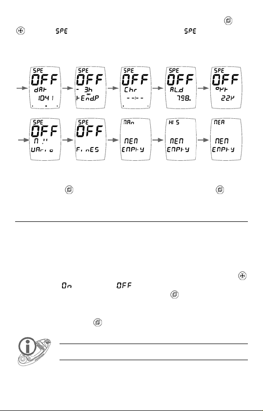
To display the special menu, press and hold simultaneously the and
buttons, flashes on the upper block. When stops flashing,
release the buttons. The special menu features 10 screens (7 screens for
special modes and 3 screens for the memories):
Navigate (switch from one screen to another) in the special menu with
the help of the
button. To exit the menu, keep pressing the button
for 2 seconds.
Enabling a Special Mode
In an effort to simplify the use of the instrument as much as possible, the
special modes are only displayed if they are so enabled beforehand; this
avoids overloading the screens with data for which some users may have
no use.
To enable/disable one or several special mode(s), enter the special menu
and display the screen of the desired special mode; then, using the
button, select
choice and exit the special menu by pressing the
Once activated, a special mode is displayed on a ‘separate’ special
screen. In order to access a special mode that has been enabled, you only
need to press briefly the
to enable or to disable the mode. Confirm your
button for 2 seconds.
To find out more on the display and use of a special mode once it has
been enabled, please refer to the following sections
button from the standard screen.
20
Page 21

Date and Time
Display
upper block: day of the week
large block : date
middle block: month
lower block: time and year
+ seconds on the bargraph
Operation
The year is displayed by pressing briefly the button, release the
button, and the time is shown again. The seconds are marked on the
compass bargraph.
Calibration
Select the date and time screen (it flashes), then keep the button
pressed down.
as soon as you access calibration. The settings are entered in the same
way as described under the ‘Starting up the Instrument’ Section.
starts flashing on the upper block. Release the button
Barometric Tendency
Display
upper block: indicates or / when viewed
large block : tendency (here variation within 24 hours)
middle block: time shift
lower block: 1. Instantaneous state (turned on for 5 sec)
2. When viewing the tendency or by
or normal state (except when viewing
tendency); displays the current pressure
(QNH).
pressing briefly the
pressures recorded in the past. (Please
refer to examples below)
button, displays the
Operation
Exactly on the hour, every hour (09:00, 10:00, etc.), the instrument
records the current QNH value or extrapolates a QNH if there are sudden
pressure variations which indicate that it is in motion.
21
Page 22

The tendency is displayed using 63 values. The first 3 values show the
variations in relation to the current pressure, the next 46 values in
relation to the last measured pressure on the hour, and the last 14 in
relation to the last pressure read at noon.
To view the tendency (only if the special mode is enabled, please refer
to Section: ‘Enabling a Special Mode’): display the barometric tendency
mode, select the middle block (it flashes), then by pressing briefly the
button, access the screens showing the tendency (the signs
and will
show you which way the data is displayed, whether in increasing or
decreasing order; change the order using the
button). The last shift
displayed becomes the default shift in the display, and will therefore
appear next time the ‘Pressure Tendency’ special screen is accessed.
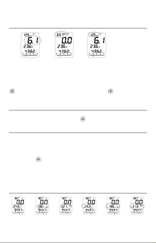
Examples of tendency display screens
Examples of display screens in relation to tendency at 11:25 on May 1st,
with a current relative pressure (QNH) of 1010.8.
The pressure displayed is the current pressure. The instrument
compares the current pressure
(1010.8) with the pressure
recorded 25 minutes ago. This shows, as a result, that in the time
span of 25 minutes, the pressure has dropped by 0.2 hPa. If the
time was 11:43, the instrument would display -43 ', etc.
The pressure displayed is the pressure taken 1h and 25 min ago,
or the pressure read at 10:00. The instrument compares the
current pressure (1010.8) with the pressure recorded 1h and 25
min ago and displays the difference. This shows that in the time
span of 1h and 25 min the pressure has dropped by 0.5 hPa. If the
time was 11:43, the instrument would display:
-1h4, etc.
The pressure displayed is that of 3 hours ago, i.e. the pressure
read at 08:00. The instrument compares the last pressure read on
the hour (here, the pressure measured at 11:00, 1011.0) with that
taken 3 hours earlier and displays the difference. This shows that
the pressure has dropped by 0.8hPa in the time span of 3 hours
The pressure displayed is that read 24 hours ago, i.e. the pressure
measured at 11:00 the day before (April 30
compares the last pressure read on the hour
th
). The instrument
(here, the pressure
.
measured at 11:00 on May 1st, 1011.0) with the pressure
recorded 24 hours earlier and displays the difference. This shows
that the pressure has dropped by 0.4 hPa in 24 hours
22
.
Page 23

The pressure displayed is that of 2 days earlier, i.e. the
pressure recorded at noon (12:00) on April 28
instrument compares the last pressure read at noon (here,
the pressure measured at noon on April 30
th
. The
th
, 1011.9) with
the pressure recorded 2 days earlier and displays the
difference. This shows that the pressure has dropped by
2.1hPa in 2 days.
Please note that the display will change 35 minutes later, since, when it is
12:00, the instrument will take this latest reading taken at noon to
compare it with the next. The pressure displayed will be that of April
th
, and the instrument will compare it with the latest pressure reading
29
taken at noon, that of today in this case, but it will still show the pressure
variation over 2 days.
If the clock has been changed and readings have been lost, the instrument
displays the
message on the lower block.
In the case of a significant variation in pressure (change in
altitude), the instrument extrapolates the QNH in order to
offer as plausible a barometric tendency as possible. Once
stabilised, the instrument will show the real QNH again. The
instrument signals when the QNH is extrapolated with the
indication
on the compass block (see opposite).
In the same way, the instrument will display the indication
to signal that a calibration has been carried out
(see opposite).
The tendency is always operating, even if the Tendency special mode
has not been enabled (OFF in the special menu). To disable the
tendency (and save the battery), access the special menu and display
the pressure tendency screen, then push the
starts flashing on the upper block; release the button as soon as
you access calibration. Using the
OFF position (indicates
automatic adjustment of altitude. Proceed in the same way when you
decide to reactivate the tendency recordings (
). This operation also cancels the
button for some time,
button set the recordings to the
).
Chronometer
Display
The chronometer mode is displayed as follows:
middle block: seconds.1/10
lower block: hours:minutes
Example opposite: 3 minutes 27 seconds and 9 tenths
23
th
of a second
Page 24

Operation
Pressing both the and buttons briefly at the same time launches the
chronometer (brief display of the message
be done from any screen, and whether the instrument is turned on or off.
Pressing briefly the button freezes the screen, which allows to read an
intermediate time (the instrument keeps counting the time while the
display is frozen). The chronometer returns to normal mode at the end of
10 seconds or by pushing on
twice.
Remark: At a later stage it is possible to view all the times recorded by
the chronometer via the memory display, since every time you start a
chronometer, you carry out a manual recording of all the measurements.
). This can
Density Altitude
Display
Operation
You have the option of changing the measuring mode displayed on the
middle block, which shows the default basic mode of the standard screen.
To change the display, select this block (it flashes), then press the
button briefly: you can display either the ambient temperature or the
relative humidity.
The density altitude is the current altitude should the air be in a
standard air environment. The density altitude is corrected using the
real air density; it therefore constitutes an essential factor in the
computation of the performance of an engine or the lift of an aircraft.
The density altitude is displayed as followed:
upper block: Wind speed
large block :
indication
middle block: default mode (here temperature)
lower block: density altitude
+ compass heading
24
Page 25

Magnetic Field in µTesla + Compass
Heading
Display
This mode is displayed as follows:
upper block: wind speed
large block : heading in degrees
middle block: indicates
block) and
lower block: magnetic field in µTesla
= micro Tesla (unit of the lower block)
Operation
The role of this mode is twofold:
1. allow a larger display of the heading in degrees
2. know the value of the magnetic field drift in µTesla in relation to the
calibration. This will give you an indication as to whether an external
element (steady magnetic field) is interfering with your compass; 0 µTesla
will indicate that no magnetic field is interfering with your compass and
that your instrument therefore offers you the highest level of accuracy.
To measure the value of an external magnetic field (a magnet for instance),
display 0 µT on the screen and bring the magnet close to the instrument:
the display shows the magnetic field o utput expr essed i n µT.
Calibration
Calibration is carried out as with the compass (please refer to relevant
section). If you already have calibrated the compass basic mode in the
standard screen, there is no need to do it again, unless you have just entered
a different environment. Please note that if you c arry out a calibration in
this special mode, it will also be vali d for the com pass bas ic mode.
Magnetic declination
If you want the compass to indicate true North instead of the magnetic
North, enter the declination (in degrees) of the location where you are at.
To adjust this declination, access the special menu and then
display the Magnetic Field screen. While the
indication is flashing, keep the button pressed down,
starts flashing on the upper block. Once in the calibration
function (see opposite) release the button. Use the
, = degree (unit of the large
or
25
Page 26

button to select the direction of the adjustment ( increment,
decrement), then set the value in degree of the declination with the
help of the
release it, and then press it down again to exit the special menu.
button. Keep the button down to confirm your setting,
IMPORTANT ! When a declination has been stored, all the display
modes of the compass will show true North and no longer the
magnetic North. Should you wish to display the magnetic North at
a later stage, you will need to reset the declination.
Variometer
Display
upper block: wind speed
large block : value
middle block: unit (here M .'' (metres per second)
lower block: default mode of the standard screen
+ compass heading
Operation
The Large block sh ows your speed. The value is positiv e, this corresponds
to the rate of ascent, whereas a negative value indicates a rate of descent.
There is a choice of two units: M .'' = m/s (metre per second) and hf. '
hft/min (100 feet per minute). To change the unit, select the middle block
(it flashes) and keep pressing the
when the desired unit is displayed.
button down; release the button
Finesse
Display
Finesse is the ratio between the horizontal velocity and vertical velocity.
It indicates the gliding performance of a paraglider or hang-glider.
This function is only of use to those individuals who practise
hang-gliding and paragliding.
Finesse is displayed as follows:
upper block: mean wind speed
large block : finesse
middle block:
indication
lower block: default mode (here relative pressure)
+ compass heading
26
Page 27
Operation
It is not possible to modify any data on the finesse screen. It is necessary
for the impeller to rotate and there must be a drop in altitude for finesse
to be displayed. To calculate finesse, the instrument takes the mean wind
speed as the horizontal velocity and the data supplied by the variometer
as the vertical velocity.
Memories, Viewing and Settings
24,480 sets of memories are available. One set contains all the readings
from all the sensors (including a combination of sensors) at the time of
recording. The 24,480 sets are shared between the 3 types of memories.
A new recording (set) deletes the oldest if the memory capacity is full.
The instrument features 3 types of memories:
- Manual recordings (
- Measurements at selected rate (
- History (
Each type of memory has its own screen (please refer to next sections).
The memory screen can only be viewed and configured through the
special menu.
Memory capacity (24,480 records):
The duration of the recording allowed will depend on the selected rate,
for instance:
2.5 days are possible if the recording takes place every 10 seconds
2.5 months are possible if the recording takes place every 5 minutes
)
Manual Recordings
)
)
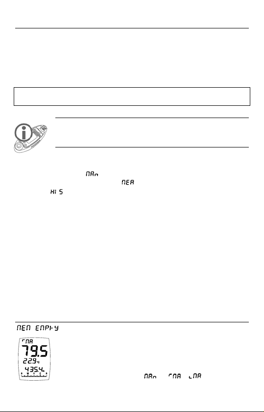
Display
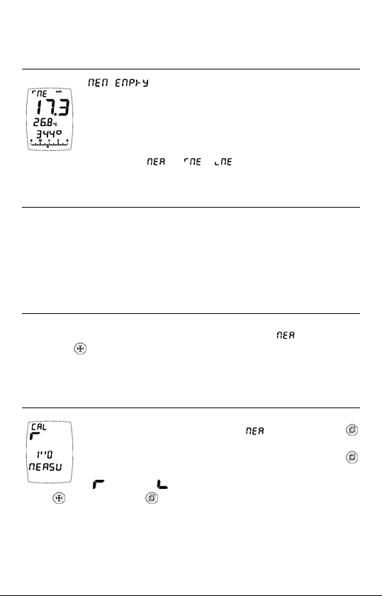
is displayed if the memory is empty (no recordings).
The default screen is used to display the memory content.
In the example shown opposite, the standard screen with
the basic measuring modes (wind speed, temperature,
altitude, compass heading) is the screen used to that effect.
The upper block displays
when being accessed.
or / which flashes
27
Page 28
Operation
This type of memory displays all the recordings carried out manually.
To record manually (from any screen, wheth er instrument turned on or
off), press simultaneously the
message indicates that the recording has indeed been
made. Please note that this button combination is also used to launch the
chronometer, hence the
Each manual recording features the time and date and stores all the
readings of all the sensors (including the combination of sensors) at the
time of the recording.
and buttons for a short time. The
indication.
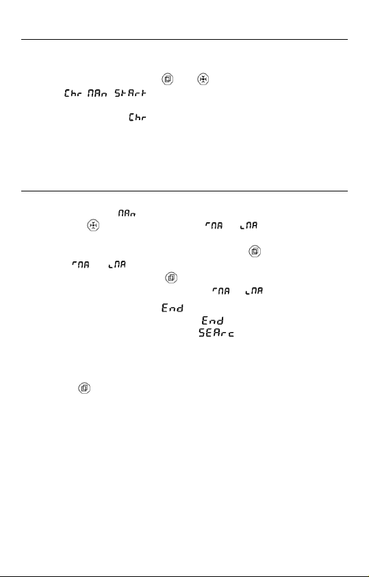
Viewing
To view manual recordings, go to the special menu and display the
Manual Recordings (
briefly on the
lets you know which way the data is viewed (increasing or decreasing
order). To change direction, press briefly the
indication
recording, double-click on the
recording in question (when the indication
When viewing recordings, the message is displayed when you get
to the end of the recordings (there is an
end of the recordings). If the message
the instrument is currently searching for data. You need to wait until the
indication disappears.
The instrument automatically exits the view mode after 5 seconds or by
pressing the
The default screen is used to display the memory content. However, you
may view other values, since the instrument stores all the readings of all
the sensors (including the combination of sensors) during each recording.
Example: You view the manual recordings and you realize that the
altitude is displayed on the lower block, when instead of the altitude at
the time of recording, it is the height that you want to know. Exit the
special menu and display the standard screen; select the lower block and
then display the height. Once this operation is completed, go back to the
special menu and display the screen for manual recordings, you will then
see that it is the value of the height (at the time of the recording) which is
displayed and no longer the altitude.
or is flashing. To view the date and time of each
button for 2 seconds.
) screen, view the recorded values by pressing
button. The indication or on the upper block
button when the
button when you have accessed the
or is flashing).
at the beginning and at the
appears, this means that
28
Page 29
Measurements Based on Selected Rate
Display
recordings).
The default screen is used to display the memory content.
In the example shown opposite, this screen is the standard
screen with the basic measuring modes (wind speed,
The upper block displays
accessed.
temperature, digital and analogue compass heading).
Operation
This type of memory displays all the automatic recordings made based
on the selected rate (configurable from 0.5 second to 24 hours). The
data is only recorded when the instrument is switched on. Each
recording features the time and date and stores all the readings of all the
sensors (including the combination of sensors) at the time of the
recording.
Viewing
To view the recordings made automatically, go to the special menu and
display the Measurements based on selected rate (
briefly the
the same as that followed for ‘Manual Recordings’ (please refer to
previous Section).
button to view the recorded values. The viewing process is
Selecting the rate of recordings
Go to the special menu and display the ‘Measurements
Based on Selected Rate’ screen (
button for some time. Release the button as soon as you
enter the calibration function (screen opposite). Use the
button to select the direction of the adjustments
(
increment, decrement), and set the rate with the help
of the
button. Keep the button down to confirm your setting.
is displayed if the memory is empty (no
or / which flashes when being
), then press
), then press the
29
Page 30

History
Display
recordings).
The default screen is used to display the memory content. In
the example shown opposite, this screen is the standard
screen with the basic measuring modes (wind speed,
humidity, relative pressure and compass heading).
The upper block displays
accessed.
is displayed if the memory is empty (no
or / which flashes when being
Operation
This type of memory displays all the automatic recordings made based
on the selected rate (configurable from 0.5 second to 24 hours). The
data is constantly being recorded, whether the instrument is turned
on or off. Each recording features the time and date and stores all the
readings of all the sensors (including the combination of sensors) at the
time of the recording.
Viewing and rate selection
The process for viewing and selecting the rate is the same as that used
for Measurements based on Selected Rate; please refer to previous
sections.
Other
States of the Instrument
The instrument features several operating states. To find out which
operating state your instrument is currently in (off or on), press 3 buttons
simultaneously and briefly, then release them. For 2 seconds, your
instrument displays: the state, the software version, and the battery level.
When the instrument is turned off, the two possible states are Storage
and OFF, while when it is switched on, the possible states are Stop Auto,
Permanent and Out PC.
30
Page 31
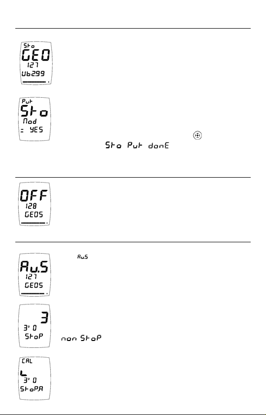
Storage
The example shown opposite indicates that the instrument
is in the storage state; the clock and sensors have stopped,
and there is no automatic recording. This is the default
state of the instrument when it comes off the production
line, thus avoiding the depletion of the battery if the
instrument is stored for a long period of time.
Should you wish to set the instrument into the storage state
yourself, please proceed as follows: when the instrument is
turned off, keep the 3 buttons pressed down for at least 4
seconds; when the screen shown opposite is displayed,
release the buttons then keep the MOD (
The message
state is activated.
OFF
The instrument is off. Both the screen and sensors are off,
but the clock and automatic recordings are still active.
The instrument switches to the OFF state after being
turned off manually or automatically (please refer to the
Section entitled “Turning the Instrument Off”).
Automatic Stop
The (auto stop) state means that the instru ment will
switch off automatically three minutes after one of the
buttons was last pressed (default setting), or when turned
off manually (see Section entitled “Turning the Instrument
Off”).
Whenever it is turned off (whether automatically or
manually), the instrument displays a countdown on the
large block and shows the time left until the auto stop (at
the end of 3 minutes in this case), or the message
permanent operation.
The time elapsed before the automatic stop may be
adjusted (from 20 seconds to 24 hours). Default setting: 3
minutes. To change this time span: turn off the instrument
manually and, when the countdown is displayed, release
means that the ‘storage’
) button down.
if the instrument was set for a state of
31
Page 32

the button, then keep the button down ( flashes on the upper
block). In the calibration mode (opposite screen), release the button. Set
the time: pressing briefly on the
the setting (
the
keep the
increment and decrement), and short and long pushes on
button are used to change the value. Once the adjustment is made,
button down for 2 seconds to confirm your setting and exit
button will change the direction of
the calibration mode.
Permanent operation
The instrument remains constantly on (it no longer turns off).
To set the instrument in permanent operation, switch it off
manually (please refer to the Section entitled “Turning the
Instrument Off”), then during the countdown leading to the
stop, release the button and press briefly on the
instrument displays
, which means that it has
button; the
switched to the permanent operation state. To go back to the ‘Automatic
Stop’ state, redo the same operation, or switch the instrument off.
If the instrument remains constantly turned on, the battery is
depleted faster, keep that in mind!
Data transfer to a PC
This requires the use of the interface and the SkywatchLog
software (available as an option). SkywatchLog itself controls the
instrument remotely.
When the instrument is transferring data to a PC, the screen displays the
message
Using induction, the instrument transfers the current sensor readings at a
selected rate. You can set the transmission frequency from 0.5 seconds to
24 hours. Go to the special menu and display the screen of manual
recordings, then press on
upper block. Release the button as soon as you enter the calibration
function (screen opposite). Select the scrolling direction by pressing
.
for a long time, starts flashing on the
briefly on the
then change the value using the
button ( increment and decrement),
button ('' = second, ' =
minute and h = hour). Please note that the default value is
(no transmission). Confirm your setting by keeping
the
button down, then release.
32
Page 33

Other states
The instrument features another two states: normal (turned on) and
instantaneous (please refer to the Section entitled “Starting up the
Instrument”).
Resets
Memory reset (deletion)
Empties the 3 types of memory, and resets the rates of automatic
recordings.
To erase all the memories, go to the special menu and display one of the
3 types of memory, then press and keep down simultaneously the 3
buttons. When the screen displays
buttons and keep the MOD (
The instrument displays the message
the deletion has indeed been successful (also resets lengths of time).
) button down for 2 seconds to confirm.
Screens reset
Reboots the display configuration by de-activating all the special screens
and formatting the standard screen as follows:
upper block: mean wind speed
large block : instantaneous wind speed
middle block: ambient temperature
lower block: altitude
compass block: heading
In order to reset, first display the standard screen featuring the basic
measuring modes (no selection), then keep the 3 buttons pressed down
simultaneously. When the screen displays
the buttons and keep the MOD (
confirm. The instrument displays the message
you that the reset operation has indeed been carried out.
General reset
This resets the screens and the memories, and reboots all the calibrations
(except for the time and date). To carry out this general reset operation:
when the instrument is off, keep the 3 buttons pressed down
simultaneously. When the screen displays all the segments (display test),
release, and once more keep the 3 buttons down simultaneously. When
33
, release the
, informing you that
, release
) button down for 2 seconds to
informing
Page 34
the screen displays the message , release the
buttons and press the MOD (
The instrument displays the message
) button down for 2 seconds to confirm.
informing you
that the reset operation has indeed been carried out.
Instrument reset
Remove the batteries for 20 minutes.
Power Supply, Battery Replacement
The instrument is supplied with two new batteries already in place (one
battery for power supply, and one for backup).
As for the diode lamp, it is entirely independent from the instrument, and
is therefore relying on its own batteries for supply (also pre-fitted), which
are the same as those used for the instrument.
Batteries fitted in the instrument
The instrument operates on a 3V ‘button’ type battery, with the reference
CR2032, which is placed behind the lid at the back of the instrument. A
second identical battery is located inside the compartment, thus acting as
a spare battery. Important note: the spare battery is also there to hold the
active battery in place, which means that the instrument can only work
properly when fitted with both batteries.
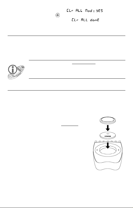
To replace the battery(ies) of the instrument:
1. Unscrew both screws and then remove lid.
2. Remove both batteries (the top battery is
the spare battery, while the battery located
at the bottom of the compartment supplies
the power).
3. Place the spare battery (provided it is new)
at the bottom of the compartment (+ facing
outward).
4. Put a spare battery back on to the supply
battery in order to keep the latter in place. The spare battery should
be placed “upside down” on the supply battery (+ against +).
Simply use the used battery if you do not have a new battery.
34
Page 35

5. Check that the round seal is properly positioned in its groove,
screw the lid back on using the 2 screws.
Always pay attention to the polarity, as positioning the batteries
the wrong way may cause damage.
Batteries of the Light Emitting Diode (LED )Lamp
It is imperative that the batteries of the LED lamp are replaced at
the same time; do not use a battery that is already used or flat
together with a new battery.
To replace the batteries of the lamp:
1. Pull the LED la mp out of the instrument. Turn
the instrument over, and with one finger, push
the lamp out of its housing.
2. Unscrew the cap (the part containing the LED),
see picture opposite.
3. Remove both used batteries and replace them
with 2 new batteries. Be mindful of the polarity.
The + facing down (see picture opposite).
4. Screw the cap tightly back on.
5. Put the LED lamp back into the casing of the
instrument.
Condition of the instrument battery
The instrument gives you the possibility to check the condition of the
battery at any time. This can be checked in 2 ways:
1. When first starting up the instrument (brand new): when
the instrument is off, press briefly on the
following indications will appear:
the instrument is in storage mode),
(the software version), and
the battery voltage is 2.99 Volts).
button: the
(this means that
(GEOS), 127
(in this example,
35
Page 36

2. While the instru ment is on, press simultaneously on the
3 buttons and then release: the following indications
will appear:
(the instrument is in the automatic
stop mode), 127 (the software version) and the segments
that are lit up (1 segment = 0.025V, no segment: <2.3V,
all the segments lit up: >3.1V).
This information is only valid for the battery supplying the
instrument. As for the Light Emitting Diode lamp, a significant
decrease in the brightness of the light will indicate that you need
to replace the batteries.
Battery lifetime
In the storage state : > 12 ye rs a
Turned off (OFF state) : 6 years
Permanent operation : 6 weeks
Constant operation + history with a
rate of 1 recording per second) : 3 weeks
A lifetime of at least 1 year when in standard use. A practical
example: instrument turned on once a day for 30 minutes + history with a
rate of 1 recording every 20 seconds.
LCD Display Test
This test is used to check if all the LCD segments are
operating. With the instrument switched off, press down
simultaneously the 3 buttons for 2 seconds; all the
segments light up (as shown opposite). To stop the
instrument, keep
down.
Temperature Compensated Quartz
The instrument uses a temperature compensated quartz clock. Should
you notice a drift however, you have the possibility of correcting this
deviation by -6.35 to +6.35 seconds per day. Go to the special menu and
display the chronometer screen, then keep the
flashing on the upper block. Release the button when you have accessed
the calibration. Use the
(
increment, decrement), then set the value using the button.
Keep the
button down to confirm your setting, release it, and then
button to select the direction of the adjustment
press it down again to exit the special menu.
36
button down, starts
Page 37

Calibration of the Pressure Sensor
Calibration is carried out from the measuring mode for absolute pressure.
Proceed in the same way as with the other calibrations. The number
displayed on the middle block indicates the shift in 1/32th hectopascals,
and the lower block shows the absolute pressure on the sensor. Other
calibrations are possible, but only via SkywatchLog.
This operation is reserved to those professionals who hold a
highly accurate laboratory standard. The consequence of any
wrong calibration will be to supply erroneous data on all the
measurements relating to pressure.
Technical Specifications
Precision
Wind speed
Temperature
Humidity
Pressure
Compass
Clock
Display resolution
Wind speed
Temperature
Windchill temperature
Dew point
Humidity
Pressure
Altitude
Density altitude
QFE height
Variometer
Barometric Tendency
Compass
Response time of sensors
Wind speed
Temperature
37
± 2%
± 0.5°C at 25°C
± 2% at 50%rH
± 0.5% at 25°C
± 3°
<0.1 second per day possible if calibrated
0.1 unit <99.9 then 1 unit >100
0.1 at 25.0 Beaufort
0.1° <99.9° then 1° >100
0.1° <99.9° then 1° >100
0.1° <99.9° then 1° >100
0.1%rH
0.1 hPa - 0.01inHg
0.1m from -999.9m to 3,000m
0.5m from 3,000 to 10,000m
1m from 10000 to 21,535m
1 unit
0.1 m - 1 ft (foot)
0.1 unit
0.1hPa - 1inHg
1°
instantaneous
From a few seconds to several minutes
depending on wind speed
Page 38

Humidity
Pressure
Compass
Measuring range of sensors
Wind speed
Temperature
Humidity
Pressure
Altitude
Perpetual calendar
Serial transmission
Measurement units
Wind speed
Temperature
Pressure
Altitude
Variometer
Operational temperatures
Easy reading
Possible reading
Very slow display but instrument able to work
(the sensors and recordings are operating correctly)
Miscellaneous
Power Supply
Impeller
Dimensions
Weight
Waterproofness
instrument: 4 x 3V lithium CR2032 button batteries supplied
1 for the instrument, 1 spare, and 2 for the LED lamp
Diameter 17.8mm (replaceable)
46 x 120 x 32 mm
171g
5 minutes at 1 metre
Wait for the humidity sensor to dry off completely before re-using the
instrument
From a few seconds to several minutes
depending on wind speed
instantaneous
instantaneous
0 to 300 (peak) km/h
-40°C to +85°C
0.1 to 100%rH
10 to 1,100hPa
-1,000 to 21,535m
until 2175
5mm between induction coils
km/h - m/s - knots - Beaufort - mph - fps
° Celsius - ° Fahrenheit
hPa (mbar) - inHg (inches of Mercury)
m - ft (feet)
m/s - hft/min (100 feet per minute)
from -10°C to + 70°C
from -20°C to -10°C
from -40°C to -20°C
38
Page 39

LIMITED WARRANTY
JDC ELECTRONIC SA extends a 12 months’ warranty over parts and
labour for this instrument, effective from the date of purchase.
JDC ELECTRONIC SA reserves to itself the right to repair or replace
any component which may have become faulty in the course of normal
use. This repair or replacement shall be carried out at no charge to the
customer (parts or labour). Transport costs however shall be borne by the
customer. This warranty does not cover damages caused by an accident,
abnormal or excessive use, or resulting from an unauthorised
modification or repair.
To avail of this warranty, please send the instrument postage paid and in
a suitable packaging to your dealer. As a proof of purchase date and
warranty consideration, it is necessary to include in the parcel a copy of
the original invoice.
39
Page 40

40
 Loading...