

Page 1
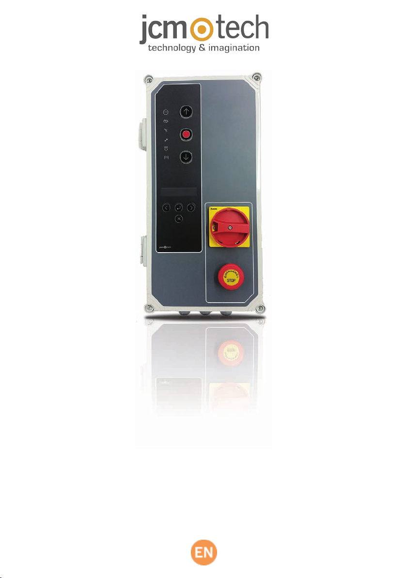
F30
User Manual
Page 2

Table of contents
Important safety instruc tions 3
Important safety instructions for inst allation 3
Important safety instructions for use 4
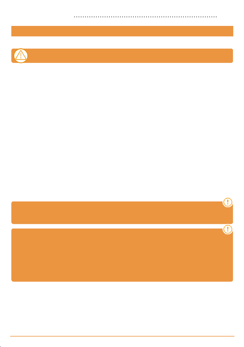
Use of the sy stem 4
Introduc tion 5
General description 5
Detailed description 5
Installation 8
Fixations of the control panel 8
Connections 9
Configurati on / Starting up 13
Option 1 selector 13
Option 2 selector 13
Connect the power supply 13
Initialization of inverter parameters 14
Speedramps adjustment 15
Checking motor direction 16
Programming 16
Manoeuvre programming with digital end limit s witch (ENCODER) 16
PROGRAMMING FOR OPENING 16
PROGRAMMING FOR CLOSING 17
Fine adjustment (for programming with absolute encoder) 17
MODIFYING THE “DOOR OPENED” POSITION 17
MODIFYING THE “DOOR CLOSED” POSITION 17
Manoeuvre programming with limit switches 18
PROGRAMMING FOR OPENING 18
PROGRAMMING FOR CLOSING 18
Partial manoeuvre programming 18
Verific ation 18
Verify that the control panel w orks correctly 18
Safety edge 18
Photocell 18
Communication’s quality (in case of RSEC3 connected) 18
Maintenance 19
Fuse replacement 19
Set parameters to default values 19
Warning of maintenance 19
Troubles hooti ng 20
F30 20
Indicator light for poss ible faults, LED ERROR 21
Technical Data 22
Electrical Parameter 22
Notes 23
Regulatory Data 24
jcmtechnologies
2
Page 3
EU Declaration of conformity 24
Important safety instructions
Important safety instructions for installation
Disconnect the power supply whenever you proceed to the installation, maintenance or repair of the equipment.
•Before installing the panel, remove all unnecessary ro pes or chains a nd disable any equipment such a s locks that is not
necessary for the automatic operation.
•Before installing the panel, check that the doo r is in good mechanical condition, correctly balanced and that it opens and
closes correctly.
•Install the manual unlocking deviceat a height lower than 1 .8m.
•Install any permanent control next to the door away from any moving part and a t a minimum height of 1.5m.
•For permanently connected equipment, an easily accessiblepower disconnection device must be incorporated into the wiring. It
is recommended that this be o f the emergency switch type.
•If the control panel is supplied without emergency stop button, this will be incorporated in the installation, connecting it to the
STOP terminal.
•For correct use of thesecurity edge, this must never be activated when the doo r is fully closed. It is wise to install theends of run
before a ctivating theedge.
•This equipment can only be handled by a specialist f itter, bymaintenance staf f or by a suitably trained operator.
•To connect the power supply and motor wiring, 2.5 mm2 section terminalsmust be used.
•Use protective go gg les when handling the equipment.
•Fuses must only be handled when the appliance is disconnected from the mains.
•The instructions for using this equipment must remain in thepo ssession of the user.
•European door normative EN 124 53 and EN 12445 specify the following minimum protection and doo r safety levels:
- for single-family dwellings, prevent thedoor from making contact with any object or limit the force of contact (e.g. safety
band), and in the case of automatic closing, it is necessary to complement this with a presence detector (e.g. photocell).
- for communa l a nd public installations, prevent the door from making contact with a ny object or limit the force of contact (e.g.
safety band), a nd complement this with a presence detector (e.g. Photocell).
F30 control panel switches automatically to dead man mode when safety devices are active or
defective. Therefore, all controls work as “hold-to-run” controls.
WARNING: IN ACCORDANCE WITH THE EN 13241-1 AND EN 12453-1 STANDARD
CONCERNING PRESSURE MAINTAINED CONTROL DEVICES:
“The person ope rating the doo r must have a direct view of the doorway, must be near the door (5 me ters maximum) during
moveme nt of the door and should not find itself in a dangerous position”. Any adjustment of the radio range out of these
recommendations, undertakes the installer in terms of responsibilityfor injury or damage.
“Releasing of the pressure maintained control device should stop the doo r movement before it sc rolls 5c ml”.
jcmtechnologies
3
Page 4

Important safety instructions for use
•Do not allow children to play with the door controls.
•Keep the remote controls out of the reach o f children.
•Watch thedoor movement and keep people a way until the door is fully open or closed.
•Precaution when operating the m anual unlocking device, as the do or may suddenly fall due to thebad
condition o f the springs or door unbalance. Details on how to use the m anual unlocking device must be
provided by them anufa cturer or the deviceinstaller.
•Examine theinstallation frequently, especiallythe cables, springs and supports, to detect signs of wear,
damag e or unbalance. Do not usethe door if repair work or adjustments are required, as this may cause
damag e.
Use of the system
Designed for automation of garage doors, in accordance with the general description. Not guaranteed for other uses. The
manufacturer reserves t he right to alter equipment specifications without prior notification.
jcmtechnologies
4
Page 5
Introduction
General description
Control panel with f requency inverter 0.75KW andcontrol by absolute encoder JCM, Elektromaten orKostal, designedfor fast
doors.
Is composed by:
•Motor brake outputs and f lashes at 230Vac, and voltage-free conta ct outputs to indicate the status of door open and door
closed.
•One 2 4V ac output and two 24V dc outputs f or the connection o f photocellswith self-test or other accessories such as radars.
Theseoutputs providea ma ximum of 700mA shared between the three.
•Pa rtial or total and closing opening pushbutton inputs.
•Inputs for safety contacts, a saf ety edge and a stop.
•External card connectors: Motion STICK receiver, RSEC3 radioband3G receiver, TL-CARD-V traffic light card and MTC1
magneticdetector card.
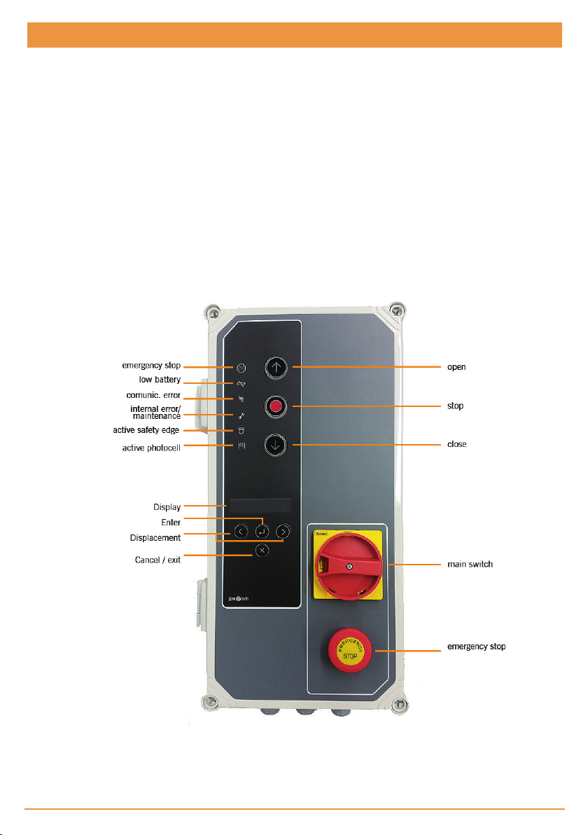
In case of activation of a safety input, if any c ontrol input is kept active, the movement of the door becomes by maintained
pressure (Dead man), and the LED on the cover indicates this by f lashing.
This control panel complies with the current electrical safety regulations EN 60335-1: 2012.
Detailed description
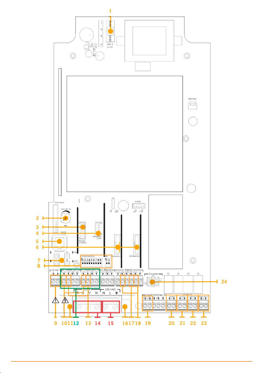
1- FUSE 14- MOTOR
jcmtechnologies
5
Page 6

1A/250V Connection f or motor U (Open) V (Close) W (Common)
2- AUTOCL OSE TIME 15- POWER SUPPLY
Min=3s - Max=60s
Maximum position=No auto-close
Power supply input connection
3- RECEIVER 16- PROTECTION EARTH (MANDATORY)
Motion STICK / DCS RACK receiver connector Connection f or earth
4- MTC 17- SAFETY EDGES INPUT/ STOP
Connector for magnetic detector card MT C Connection f or 8k2 band / Stop pushbutton
5- REMOTE CONNECTOR 18- PUSHBUTTONS INPUTS
Connection f or VERSUS-PROG programmer Connection f or external buttons (Partial opening, Opening and
Closing)
6- EXPANSION CARDS 19- END LIMIT SWITCHES
RSEC3 Radiobandreceiver connector
TL-CARD-V Connector
Open and close end limit switches
7- PROGRAMMING PUSHBUTTONS 20- OPENED
Open and close manoeuvre programming Voltage-free contact (indicates door opened)
8- OPTION SELECTORS 21- CLOSED
Voltage-free contact (indicates door closed)
9- 24VDC OUTPUT 22- FLASH LAMP
Fixed output 700mA, shared with all 24v outputs Connection f or 230Vac f lash lamp
10- 24VDC / TEST OUTPUT 23- MOTOR BRAKE
Output for photocell tests, 700mA sharedwith all 24v outputs Connection for 230Vac motor brake
11- PROTECTION EARTH (MANDATORY) 24- ENCODER INHIBIT ION
Connection f or earth Remove the jumper for connecting the encoder
12- SAFETY CONTACT INPUTS
Connection f or photocells 1 (Open) and photocells 2 (Close)
13- 24VDC / TEST OUTPUT
Output for photocell tests, 700mA sharedwith all 24v outputs
jcmtechnologies
6
Page 7
jcmtechnologies
7
Page 8
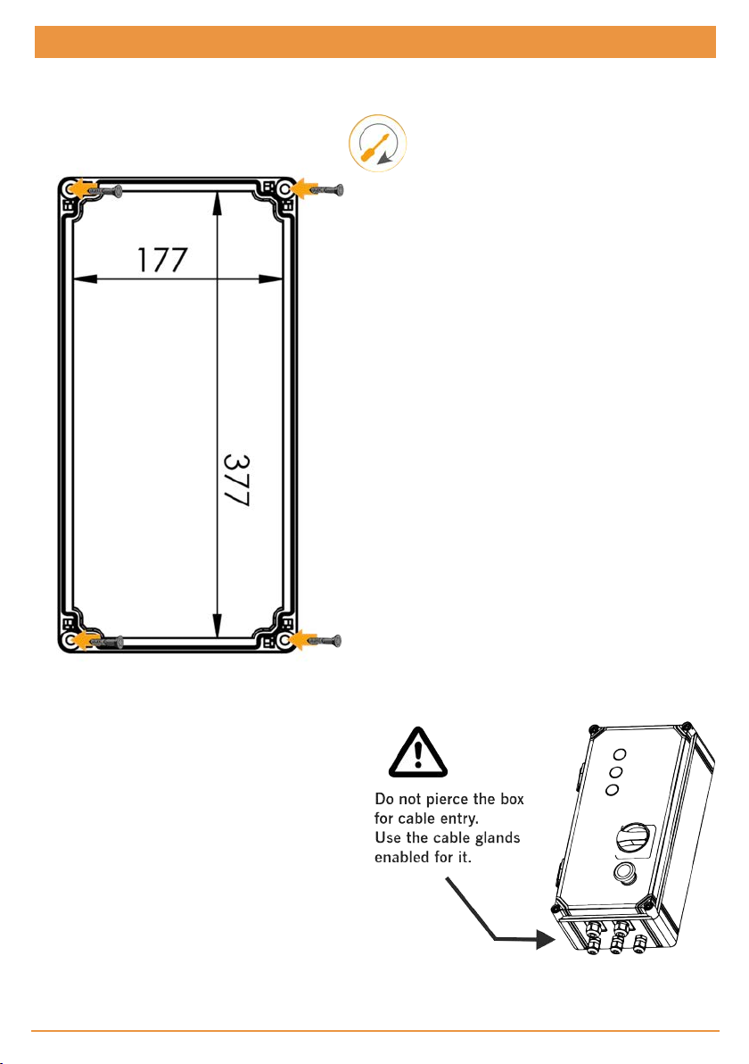
Installation
Fixations of the control panel
Install the c ontrol panel vertically on the wall at a height of 1.5m and following the assembly instruct ions.
jcmtechnologies
8
Page 9
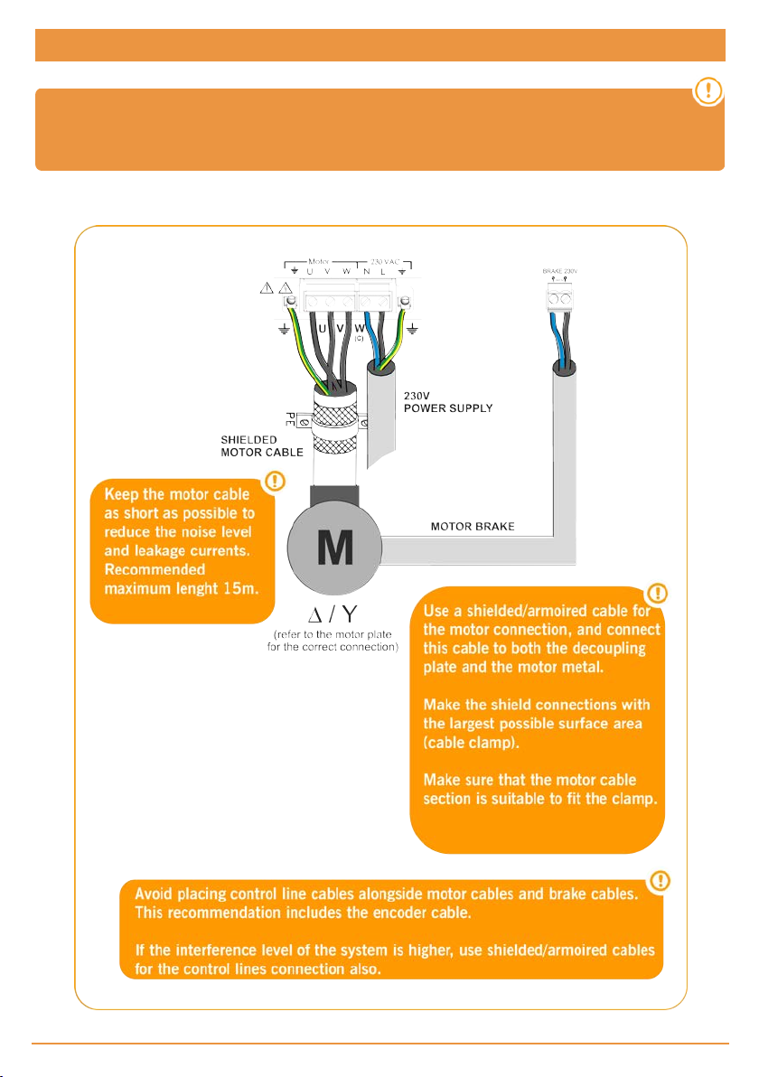
Connections
To avoid electric shock, the equipment must be disconnected from the power supply and all
electrical connections
POWER SUPPLY AND MOTOR CONNECTION
jcmtechnologies
9
Page 10
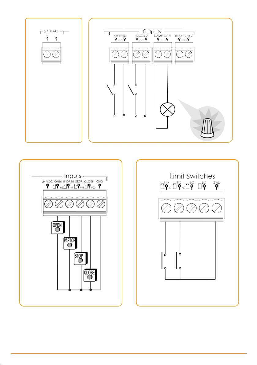
OUTPUTS
PUSHBUTTONS LIMIT SWITCHES
jcmtechnologies
10
Page 11
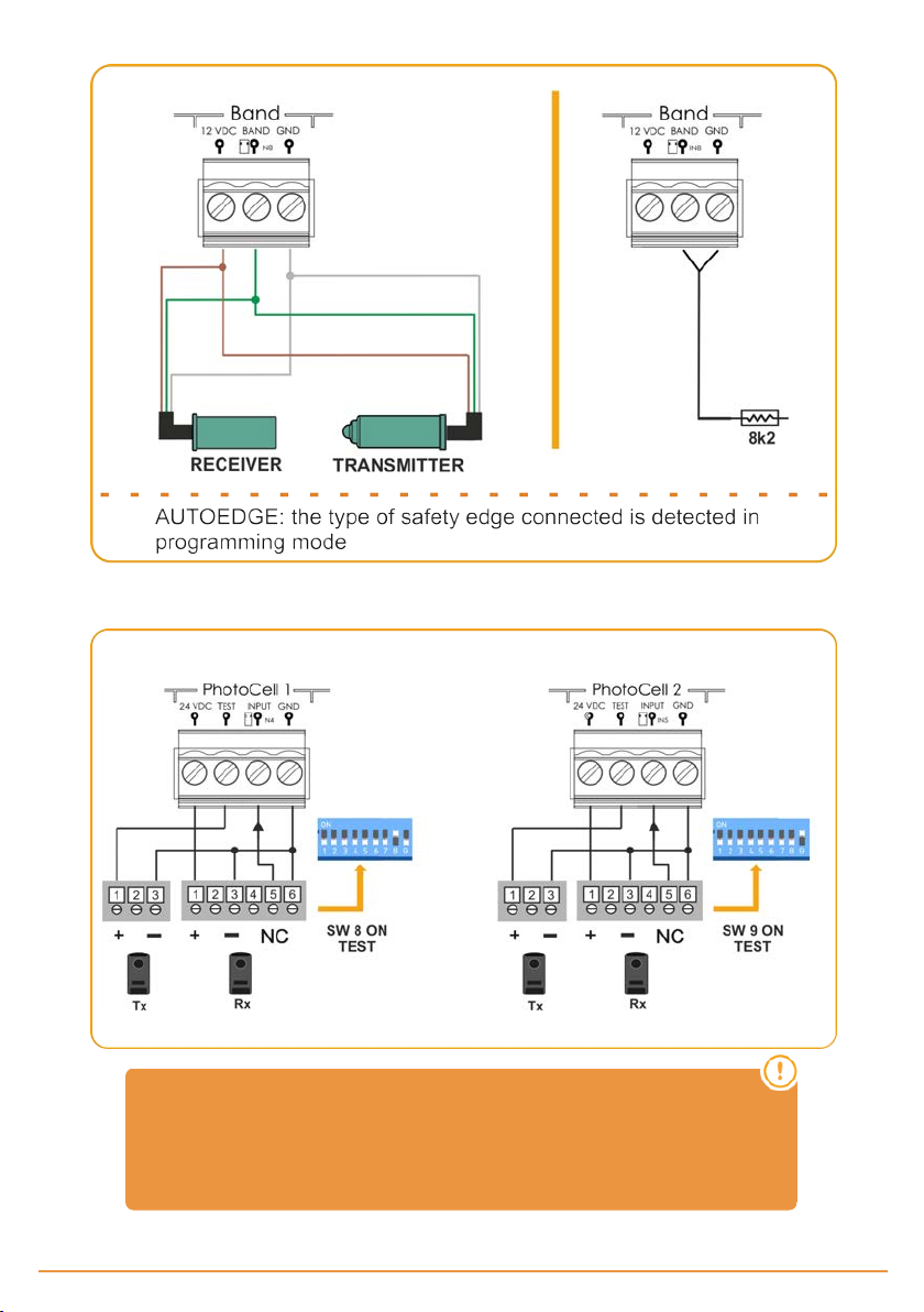
OPTO SAFETY EDGE INPUT / 8K2 SAFETY EDGE INPUT (AUTOEDGE)
PHOTOCELLS INPUTS
Normally, by default, PhotoCell1 is configured for opening safety and
PhotoCell2 2 for closing safety.
Check the configuration of the control panel parameters to be sure.
jcmtechnologies
11
Page 12
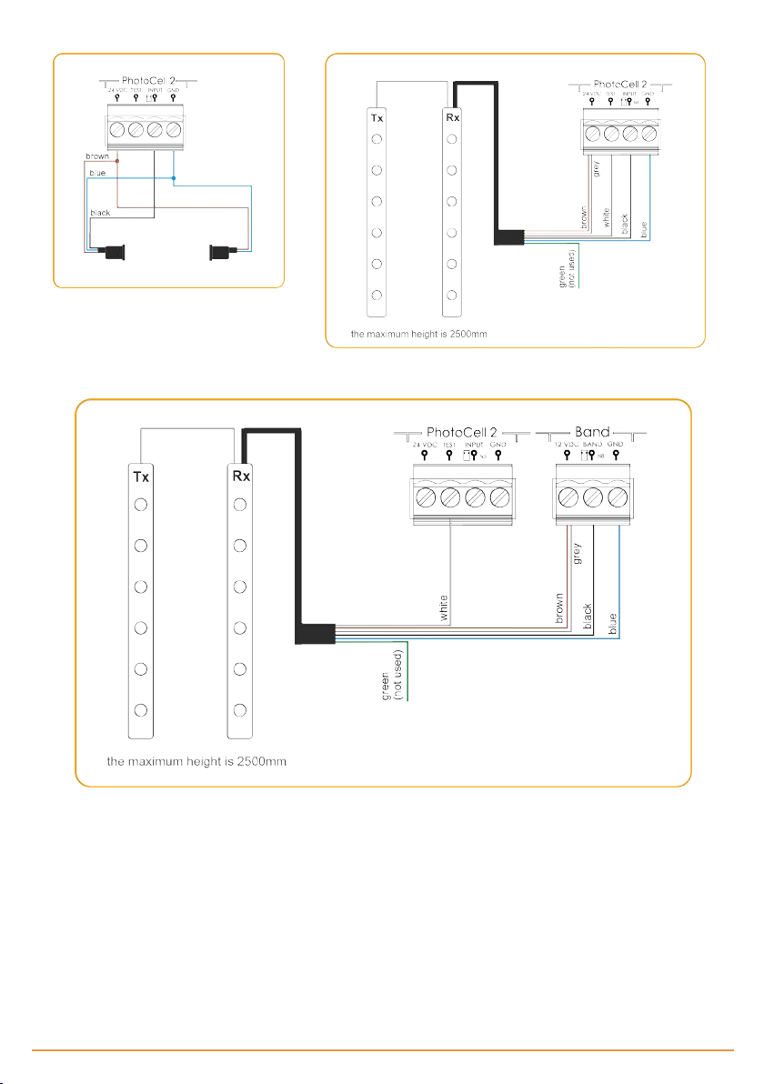
NPN PHOTOCELLS INPUTS NPN PHOTOCELL BARRIERS INPUTS
FSS PHOTOCELL BARRIERS INPUTS
jcmtechnologies
12
Page 13

Configuration / Starting up
Option 1 selector
By default all selectors leave the factory set to OFF.
SELECTOR OPTIONS 0FF 0N
1- AUTOCLOSE Do not closesautomatically Closes automatically
2- DM OPEN
3- DM CLOSE
4- NO PREFLASH / PREFLASH Without pre-flash Activates the pre-flash function
5- BREAK / NO BREAK Activates motor brake function Deactivates motor brake function
6- NO STOP ON OPENING
7- CLOSE BY SEC.CL.
8- TEST OP
9- TEST CL
Functioning without dead man on
opening
Functioning without dead man on
closing
Start button performs an stop at
opening
Deactivates closing bysecurity contact
Does not per form auto-test of the
opening security contact
Does not per form auto-test of the
closing security contact
Activates the dead man on opening
manoeuvre
Activates the dead man on closing
manoeuvre
Start button opens until total opening
Activates closing by security contact
Activates the opening security contact auto-test.
Activates the closing security contact auto-test.
Option 2 selector
SELECTOR OPTIONS 0FF 0N
Activates the fine adjustment function ( on ly functionin g with
digital end limit switch es)
Activates functioning bymechanical
limit switches input
1- FINE ADJ
2- ENCODER ABS/ LIMIT
SWITCH
Deactivates the fine adjustment
function
Activates functioning bydigital end
limit switches connector
(ENCODER connector)
Connect the power supply
Before powering up the panel, leave the door in half way.
Power up the control panel and f irst of all initialize the inverter parameters and adjust the speed ramps.
jcmtechnologies
13
Page 14
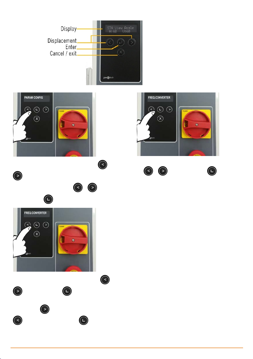
Initialization of inverter parameters
To initialize the inverter parameters, press the or
key for 2s to enter PROGRAMMING, select the
PARAM CONFIG menuwith the or key and
validate with the Enter key.
Select the desired parameter t o modify with the or
key and validate with Enter key. The mes-
sage PLEASE WAIT DATA LOADING will appear on the
display. Press key to move the pointer andpress
to increase the number. Press Enter key to
validate.
Once inside, select the FREQ.CONVERTER menu with
the or key and validate with Enter k ey.
The message PLEASE WAIT DATA LOADING will
appear on t he display
jcmtechnologies
14
Page 15
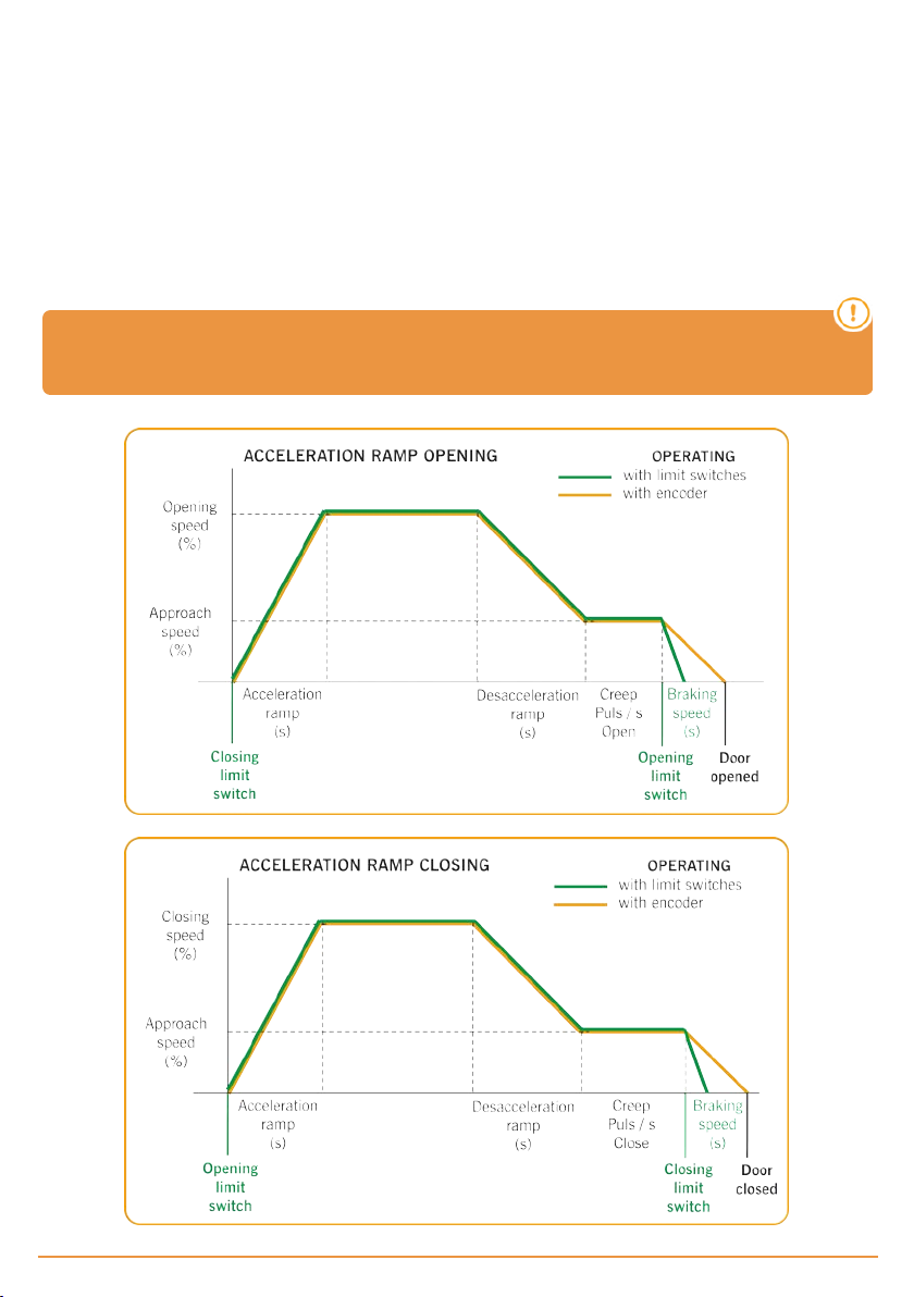
The parameters that must beentered and foundin t he motor plate are the following:
•FC Motor Freq: mo tor frequency
•FC Motor Power: enginepower
• FC MotorCurrent: motor current
•FC Motor RPM: motor revolutions per minute
Speed ramps adjustment
Once t he "opendoor" and "closed door"points have been programmed, the programming of the doorwill becalculated auto-
matically from the VERSUS parameters indicated below.
Follow the initialization sequence of the drive parameters on page 14 to access them.
The door speed profiles will be calculated accordingto the f ollowing pattern:
*Once the sequence has been programmed, the mentioned parameters can be changed with the
appropriate display or programmer and the speed profiles will be recalculated.
jcmtechnologies
15
Page 16
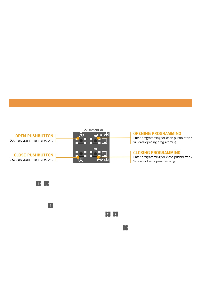
•FC PosRamp Time: acceleration ramp (seconds f rom 0% to 100 % of the speed)
•FC HighSpeedOpen: opening speed (%)
•FC NegRampTime: deceleration ramp (seconds from 100% to 0% of the speed)
•FC Creep Speed: approach speed (%)
•Creep Puls Open: approach pulse / time (seconds when o perating with limit switches)
•FC HighSpeedClose: closing speed (%)
•Creep Puls Close: approach pulse/ time (seconds when operating with limit switches)
•FC QuickStopTime: braking ramp (seconds from 100% to 0% of thespeed) when operating with limit switches
Other parameters:
•FC DCBrake Speed: indicates thespeed f rom where DC Brake is activated
•FC Brake Speed: indicates the speed f rom where Brake is activated
Checking motor direction
1. Turn theOptions 2 selector to the ON position
2. Press the Open button on thecover and check that thedoor opens.
3. If it fails to open, disconnect the power supply and swap over the wires to the motor. Or change the parameter P38 (Moto r
Out Invert) to ON, with the VERSUS-PROG prog rammer.
Programming
Once configured all t he parameters and performed t he s tart-up, proceed to program it.
When programming, it is preferable to make medium and/or long runs to short ones (in order t o improve hyst eresis and inertia).
The manoeuvre programming will be done in creep s peed.
Manoeuvre programming with digital end limit switch (ENCODER)
Turn t he option 2 of the Options 2 s elector to t he OFF position.
Only t he buttons on the board can be used, and these will f unction in dead man mode.
PROGRAMMING FOR OPENING
Press the PROG button for 3 seconds, the indicator light will come on.
1.
Position the door in the do or open point using the buttons . It is advisable to mak e long runs in order to ensure a
2.
correct adjustment.
Oncethe door is in thedesired “do or opened” position, press the PROG button to validate the “door opened” position.
3.
The indicator light willf lash a num ber of times and then g o out.
jcmtechnologies
16
Page 17
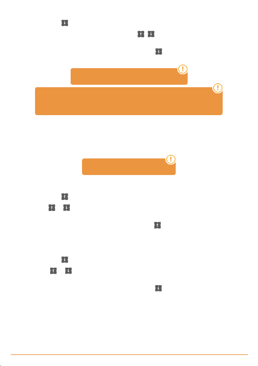
PROGRAMMING FOR CLOSING
Press the PROG button for 3 seconds, the indicator light will come on.
1.
Position the door in the do or closed point using the buttons . It is advisable to mak e long runs in order to ensure
2.
a correct a djustment.
Oncethe door is in thedesired “do or closed” position, press thePROG button to validate the “door closed” position.
3.
The indicator light willf lash a num ber of times and then g o out.
The STOP button aborts the programming
If you connect an RSEC3 to use external safety elements, you must
reprogram the maneuver.
Fine adjustment (for programming with absolute encoder)
Once the manoeuvre has been programmed, a fine adjustment of the programmed “door open” and “door closed” position can
be made.
Situate option 1 of the Options 2 selector in the ON position. The indicator lights will flash continually. Door is not moved with
this selector in ON position.
In this mode, door does not moved.
MODIFYING THE “DOOR OPENED” POSITION
Press the PROG button. The indicator light willcome o n.
1.
Press the or button to increase or decrease the “door open” position. Each press will be approximately equivalent
2.
to 1 cm (this valuedepends on theabsolute encoder resolution).
Once the “door opened” position has been adjusted, press the PROG button to validate the “door opened” position".
3.
The indicator light willf lash a num ber of times and then g o out.
MODIFYING THE “DOOR CLOSED” POSITION
Press the PROG button. The indicator light willcome o n.
1.
Press the or button to increase or decrease the “door closed” position. Each press will be approximately equi-
2.
valent to 1 cm (this value depends on the absolute encoder resolution).
Once the “door closed” position has been adjusted, press the PROG button to validate the “door closed” position".
3.
The indicator light willf lash a num ber of times and then g o out.
Situate option 1 of the Options 2 s elector in the OFF position. The indicator lights will turn off.
jcmtechnologies
17
Page 18
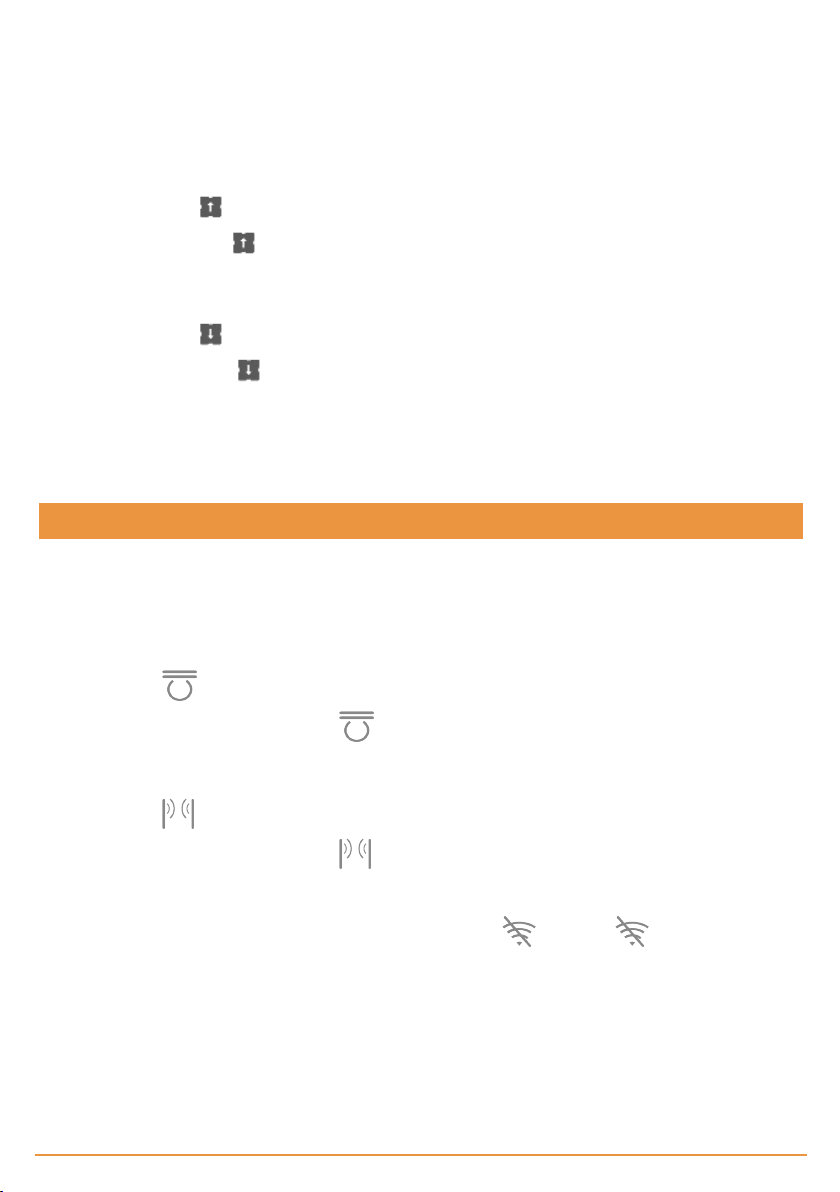
Manoeuvre programming with limit switches
Turn t he options 2 of the Options 2 selector t o the ON position.
Jumper on t he encoder connector must be plugged.
The limit switches need t o beadjusted before programming, and the door positioned in the “door closed” position.
PROGRAMMING FOR OPENING
Press the PROG button for 3 seconds. Theindicator light will come on.
1.
Press the Open button . Thedo or will open automatically until it fo unds theopening limit switch.
2.
PROGRAMMING FOR CLOSING
Press the PROG button for 3 seconds. Theindicator light will come on.
3.
Press the Close button . The door will close a utoma tically until it founds the closing limit switch
4.
5. End of program ming, the indicator light will flash a number of times and then go out.
Partial manoeuvre programming
Bridgethe Partial opening input IN7 and proceeds to programme accordingto encoder or limit switches, as desired.
In this case, the “door opened” position will be located at the half way point of the run.
Verification
Verify that the control panel works correctly
Once t he control panel is properly wired and programmed, check that the entire system (accessories included) is working cor-
rectly.
Safety edge
Check that the LED is at OFF.
If it is activated when the door's moving, the LED will pass at ON, indicating the activation of t he safety edge.
Photocell
Check that the LED is at OFF.
If it is activated when the door's moving, the LED will pass at ON, indicating the activation of t he photocell.
Communication’s quality (in case of RSEC3 connected)
To ensurethat the radio communication is good enough, check that t he LED is at OFF. If is permanently activated,
please check RadioBand3.
jcmtechnologies
18
Page 19
Maintenance
Fuse replacement
When connecting the equipment to t he power s upply, if the front panel does not light up, open the front cover and replace t he
fuse with another of the same characteristics.
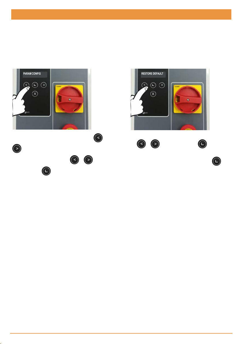
Set parameters to default values
If you desireto set the parameters to the default values, you must enter into t he frequency converter parameters menu as
explainedbelow, and s elect the RESTORE DEFAULT option.
To initialize the inverter parameters, press the or
key for 2s to enter PROGRAMMING, select the
PARAM CONFIG menuwith the or key and
validate with the Enter key.
Once inside, select the RESTORE DEFAULT menu with
the or key and validate with Enter k ey.
Then s elect RESTORE ALL, and the message
CONTINUE? will appear on the display. Press
Enter key to validate.
Warning of maintenance
The limit of maneuvers has been overflown. You must reset the PC0 parameter (Maintenance counter) to 0, with the display
menu or with the VERSUS-PROG programmer.
jcmtechnologies
19
Page 20
Troubleshooting
F30
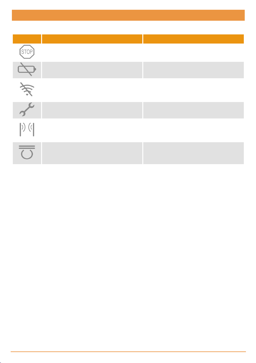
INDICATOR ON SOLUT ION
Emergency stop input activated
Low battery detection Verify the batteries of the safetytransmitter
Verify the radio signal. Checkthe batteries,
Radio communication er ror
reprogram again or change equipments location.
ON: Installer mode
Flashing: Maintenance warning
ON: Closing photocellactivation error
Flashing: Indicatesthe reversed movement
after a safetydetection
ON: RS3 / Safety edge activation
Flashing: Indicatesthe reversed movement
after a safetydetection
See Maintenance chapter
jcmtechnologies
20
Page 21
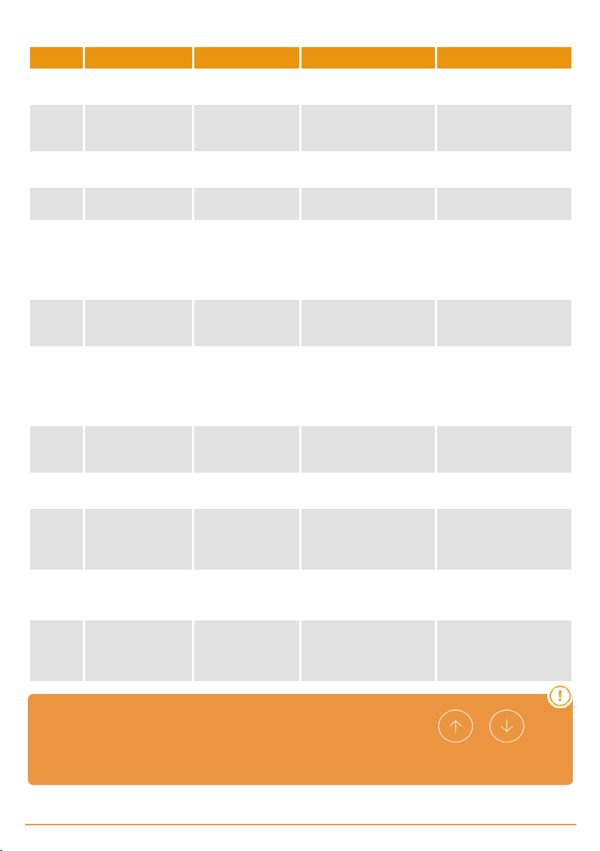
Indicator light for possible faults, LED ERROR
ERROR LED ERROR INDICATION SOLUTION
ER02 INTERNAL ERROR
ER09 MAX. PROG.TIME
ER12
ER13
ER19
CLOSING SAFETY
EDGE ERROR
OPENING SAFETY
EDGE ERROR
CLOSE TEST
ERROR
ER26 STOP
ER30
ER31
RBAND DOES NOT
EXIST
RBAND NC IN
PROG
ER32 FC NOT LEARNT
ER39 PANEL LOCKED
ER41 ENCODER ERROR
FREQ.
EP43
CONVERTER
ERROR
10 slow flashes
2 quick flashes
10 slow flashes
9 quick flashes
1 s low flash
2 quick flashes
1 s low flash
3 quick flashes
1 s low flash
9 quick flashes
2 s low flashes
6 quick flashes
3 s low flashes
10 quick flashes
3 s low flashes
1 quick flash
3 s low flashes
2 quick flashes
3 s low flashes
9 quick flashes
4 s low flashes
1 quick flash
4 s low flashes
3 quick flashes
Internal error
The maximum permitted
programming time has
been exceeded
Closing safety edge er ror
Opening safety edge error
Closing safety contact
autotest error
The panel hasstopped
due to a STOP or due to
an encoder STOP
The panel had been programmed with RBAND
and it is no longer there
The panel hasnot been
programmed with RSEC3
Error in limit switches
learning
An attempt has been
made to enter programming with the panel
locked
No absolute encoder
found or the encoder itself
is returning an error
Frequency converter
error
Consult the technical service
Program a shorter time
manoeuvre than the maximum permitted
Check the closing safety
band connections
Check the opening safety
band connections
Check that the device connected to the closing
safety contact isin good
condition and correctly
installed
Check that the STOP input
has been activated
Re-pr ogram the panel
without RBAND or connect the RBAND with
which the panel had been
programmed
Re-pr ogram the panel
with the RSEC3 card connected
Check the motor’s internal
limit switches
Enter the password with
the VDPLAY or VERSUSPROG to unlock the control panel
Check absolute encoder
connection.
Check fr equency converter parameters configuration or check
connections.
In case of any safety error, the door can be moved keeping pressed the or or any
other input controls
jcmtechnologies
21
Page 22

Technical Data
Electrical Parameter
Parameter Value
Power supply 230Vac
Maximum motor power 230Vac 3~0,75kW
Optional cards (EXPANSION1/EXPANSION2) RSEC3, TL-CARD-V
Receiver card connector Motion STICK / DCS RACK
230V output Motor brake and flashing
Voltage-free outputs OPEN/CLOSE door status signals
24Vac / 24Vdc / 24Vdc TEST outputs
ENCODER connector
Auto-close time Adjustement fr om 3s to 60s
Operating temperature -20ºC to 55 ºC
IP rating IP55
Size 305 x 225 x 126 mm
Inverter Danfoss FC51
Accessories power supply/ Photocellstest (shared
700mA)
Connector for absolute encoder JCM / Kostal / Electromaten
jcmtechnologies
22
Page 23

Notes
jcmtechnologies
23
Page 24

Regulatory Data
EU Declaration of conformity
JCM Technologies declares that the product F30 complies with the relevant fundamental requirements of the Machine Dir-
ective 2006/42/EC as well as with the Directives 2014/30/EU on electromagnetic compatibility and 2014/35/EU regarding low
voltage whenever its usage is foreseen; andwith the 2011/65/EU RoHS Directive.
See website www.jcm-t ech.com/declarations/
JCM TECHNOLOGIES, SA
C/COSTA D'EN PARATGE, 6B
08500VIC (BARCELONA)
SPAIN
UM_3201022_F30_EN_Rev07
jcmtechnologies
24
 Loading...