

Page 1
CONT-R15
User Manual
Page 2

Table of contents
General description 3
Connection 3
Technical charac teris tics 4
Installation 4
Fitting the casing (only box version) 4
Important considerations f or start-up 4
Oper ating 5
Reference search funct ion 5
Door operation control function with external clock 5
Back Jump Function 5
Opti on switch 6
Input s wi tch 6
Light indicators 6
Opti on switch bridgi ng 7
Current limit level swi tch jumpers 7
Buttons 7
Times 7
Programming 8
Self-prgramming 8
Manual programming 8
Partial opening programming 8
Sensivity programming 8
Parameter configuration from programmer 9
Receiv er operati ons 10
Manual programming 10
Normal programming 10
Programming for pedestrian function 10
Programming by radio 10
Code cancell ation (Total reset) 11
Opti onal cards 11
Receiver card 433MHz / 868 MHz 11
Traffic light card / Flash card (TL-CARD) 11
Traffic light card 11
Flash card 11
Troubles hooti ng 12
Use of the equipment 12
Regulatory Data 12
EU Declaration of conformity 12
jcmtechnologies
2
Page 3
General description
Control panel for 24 Vdc motors on sect ional, swing, folding and slidingdoors f or residential and communal use.
Basic features:
Self-programming, stoppage by consumption, receiver incorporated pluggable, resist ive safety edge input, encoder input
(sensor hall), slow-speed start of operations, slow-speed end of operations, connection to portable programmer.
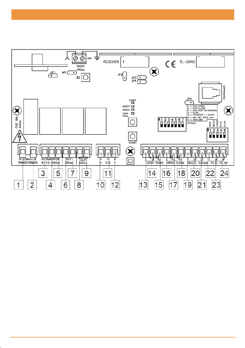
Connection
1 Primary 230V ac Transformer +
230Vac power supply (L)
2 Primary 230V ac Transformer +
230Vac power supply (N)
3 Secondary 0V ac Transformer 11 Encoder (S.H.) 19 Common securities
4 Secondary 12V ac Transformer 12 Encoder (-) 20 Close security contact (NC)
5 Secondary 24V ac Transformer 13 Common buttons 21 Resistive security edge 8K2
6 24V acoutput 14 Stop (STOP) (NC) 22 Common ends of run
7 24V acoutput 15 Start (START) (NO) 23 End of run close ( NC) (FC.CL)
8 24V dcmotor 16 Common buttons 24 End of run open (NC)
9 24V dc motor 17 Open (OPEN) (NO)
10 Encoder (+) 18 Close (CLOSE) (NO)
(SEC.CL)
(S.EDGE)
(FC.OP)
jcmtechnologies
3
Page 4
Technical characteristics
Parameter Value
Panel supply 0-12-24Vac
Transformer 0-12-24Vac / 100VA or 150VA
Receiver
Optional cards
Security device output 24V ac/ 400mA
Operating temperature -20ºC to +85ºC
Watertightness IP54
Equipment category Class II
Base plate size 160x83x27 mm
Box size 225x195x85 mm
868,35MHz incorporated 15 codes/ 433.92 / 868.35 MHz pluggable
(depending on version)
Pluggable receiver card (433,92 (bi-channel) / 868,35 MHz) and traffic
light card (TL-CARD)
Installation
Disconnect the power supply whenever you proceed to the installation, maintenance or repair of the equipment.
Fitting the casing (only box version)
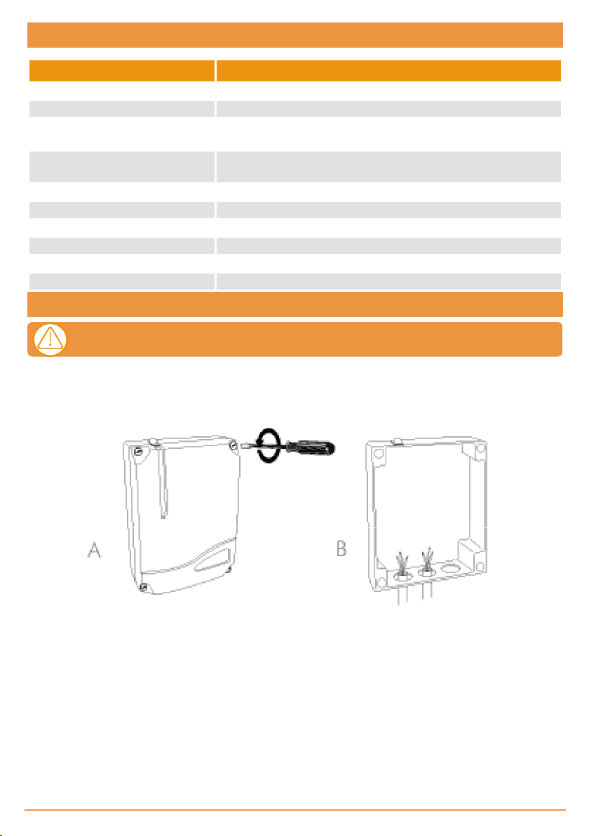
•Pa rts: front casing and container bo x.
•Unscrew the securing points. Insert the cables throug h the lower holes.
Important considerations for start-up
Where inversions are made, the panel adds time to ensure the door closes.
Any optional cards must be connected to t he panel with the power supply disconnected.
jcmtechnologies
4
Page 5

Operating
Contact normally open to open and close. F irst time the button ispressed, it
Start
Stop (STOP)
Open (ABR.)
Close (CER.)
Security contact (SEC.CL)
Security edges (S.EDGE)
Ends of run (FC.CL/FC.OP)
24 Vacoutput
Encoder input (+, S.H., -)
opens; the second time (if it has not reached the end of the run), it stops and
the third time itcloses. If it ispressed while the door is closing, it will stop and
invert the operation
Contact normally closed. This detains the operation on standbyfor a new
order. Where not used, turn option 1 on the input switch to ON
Contact normally open to open. If it ispressed while the door isclosing, itwill
stop and open
Contact normally open to close. If it is pr essed while the door is closing, it will
stop and close
Contact normally closed, photocellor magnetic detector type. This acts on
opening and closing, causing stoppage and inversion. Where not used, turn
option 2 on the input switch to ON
Resistive contact for two parallel resistivesecurity edges. This acts on closing, causing stoppage and inversion. Where not used, turn option 3 on the
input switch to ON. Where option 6 of the optionsswitch is turned to ON, the
band isinhibited during the last 4 cm of door closure
Contacts normallyclosedto mechanicallyindicate the open and closed end
of run. Where not used, turn option 4 or 5 on the input switch to ON
To power any equipment at a voltage of 24 Vacwith a maximum consumption of 400 mA
Allowsfor an NPN-type encoder (or sensor hall) to be connected at 5 Vdc,
necessary for the operation by pulses.necessary for the operation by pulses
Reference search function
If the panel loses power halfway through the operation, on receiving power it goes into reference search mode, in such a way
that the door will move until a mechanical stop orthe endof the run is reached, with preference given to the opening reference,
if it exists. Reference search is indicated by the corresponding f lashing of the SAFETY light (see table).
The Aut ref Search parameter (configurable by means of programmer) is selected if the user requires this automatic search or
wishes to wait for the START button to be pressed for t he reference search.
The panel may lose the reference if the power is disconnected halfway
through the operation.
Door operation control function with external clock
By connecting an external clock or timer (normally open) between the common push button terminal (16) and t he bridged Open
and Close terminals (17and 18), it is poss ible to temporize the opening and closing of the door.
Back Jump Function
With this function, the panel causes a small delay in the door at the end of the operation t o prevent voltage in the mechanism
or t o avoidpressure on the safety edge, where applicable. The t ime of t he delay can be defined usingadvanced programmer
parameters.
jcmtechnologies
5
Page 6

Option switch
Option No. Upper position – ON Lower position - OFF
1 (AUTO PROG) Self-programming
2 (AUTO CLOSE.) Automatic closure
3 (NON STOP ON OPENING)
4 (SLOW)
5 (COURTESY L / ELECT)
6 (INH.SEC.EDGE 4cm)
7 (DEAD MAN) Dead-man operations
Does not allow for radio reverse on
opening
Allowsfor slow speed (default
option)
Garage light comes on (default
option). Garage light contacttime =
Operating time + 30 seconds.
Inhibitsthe securityedge for the last
4 cm of the run
Manual programming (default
option)
Does not close automatically
(default option)
Allowsfor radio reverse on opening
(default option)
Does not allow for slow speed
Works like an electro-lock(1.5
seconds before opening)
Does not inhibit the security edge
(default option)
Semi-automatic or automaticoperations (default option)
Input switch
Upper position – ON (default
Option No.
1 (STOP) Stop button not connected Stop button connected
2 (SEC.CL.)
3 (S.EDGE) Security edge not connected Security edge connected
4 (FC.CL.) End of run close not connected End of run close connected
5 (FC.OP.) End of r un open not connected End of run open connected
Security Close contact not connected
option) Lower position - OFF
Security Close contact connected
Light indicators
Function Indicates Default status
POWER Power Nor mally on
SAFETY Operating alert (see table) Normallyoff
ERROR Operating fault (see table) Normally off
TIMER PROG. Operation programming mode Normally off
RADIO PROG. Radio programming mode Normally flashing
jcmtechnologies
6
Page 7

Option switch bridging
JP1
JP2
JP3
Integrated radio disconnection (where a pluggable receiver card is used, the cut bridge provides
greater range)
Pedestrian channel disconnection of the pluggablereceiver card (where a single-channel
RACK+DCS is used, thisbridge must be cut)
Select if the pr ogramming is carried out bypulsesor by time. With the jumper at ON the panel will be
programmed by pulsesand with the jumper removed it willbe programmed by time.
Current limit level switch jumpers
JP4 at ON Normal level of current limit
JP4 cut off High levelof current limit
Buttons
START Start
TIMER PROG. Start pulse or time programming
RADIO PROG. Start transmitter programming
Times
Controlling Minimum Maximum
Motor operating 3s 10min
Wait for automatic close 3s 10min
jcmtechnologies
7
Page 8

Programming
•If sto ppage is required during programming, the control pa nel exists programming automa tically for safety reasons.
•Before starting any type of operation progra mming, the corresponding options must be correctly selected (option switch, input
switch and option switch bridging) and the saf ety elements must be connected, where a pplicable.
•Operations can be programmed indifferently using the TEST / START button or through a previouslyprogra mmed transmitter.
•If in programming mode for 30 seconds without programming, the equipment will exit programming mode and theTIMER
PROG. led will switch off.
Self-prgramming
Press the TIMER PROG butt on to enter programming. The TIMER PROG. ledwith light up. Use the TEST or the START but-
ton or a transmitter to start programming t he run. After the button is pressed for t he f irst time, the door will open slowly (if
option 4 of the options switch is turned to ON) until a mechanical stop is reached or the Open limit switch is enabled. I t will then
close until it reaches a mechanical stop or the Close limit switch is enabled. Immediately afterwards, the panel begins t o oper-
ate, carrying out all of the operations programmed and memorising the consumption of the runs. Once consumption mem-
orising is complete, the TIMER PROG led will switch off.
The panel is programmed with the following fixed parameters: Slow-speed operations are 15 % of total operations, partialopen-
ing is equivalent to 2/3 total opening and the automatic closure st andby time is 30 seconds (total opening and partial opening).
Where limit switches or mechanical stops are not used on either of the two ends of the door, the
START button must be pressed to indicate the limit of the run at the end of the door without the
limit switch or mechanical stop.
Manual programming
Press the TIMER PROG butt on to enter programming. The TIMER PROG. ledwith light up. Use the TEST or the START but-
ton or a transmitter to programme t he run. The first time the button is pressed, it opens. After the button is pressed for the
second time, the opening movement will slow down (if option 4 of the options switch is turned to ON) until a mechanical stop is
reached or the Open limit switch is enabled and the automatic standby t imer will begin. The third time it is pressed, it stops the
automatic standby timer and c loses. After the button is pressed for the f ourth time, the closure movement will slow down (if
option 4 of the options switch is turned to ON) until a mechanical stop is reached or the Open limit switch is enabled. I mme-
diately afterwards, the panel then begins t o operate, carrying out all of the operations programmed and memorising the con-
sumption of t he runs. Once consumption memorisingis complete, the TIMER PROG led will switch off.
Where limit switches or mechanical stops are not used on either of the two ends of the door, the
START button must be pressed to indicate the limit of the run at the end of the door without the
limit switch or mechanical stop.
Partial opening programming
In programming, use the second recorded transmitter channel button to programme partial opening. Thenprogramme as
required using the steps described above.
Sensivity programming
The control panel must be installed on the door and the operation programmed correctly to programme sensitivity. Follow t he
steps below:
jcmtechnologies
8
Page 9

1. Press the programming button for more than 10 seconds untilthe safety led (or error led, depending on the model)
flashes.
2. Releasethe prog ramming button. The safety (or error) led will f lash between 1 and 10 times. This is the sensitivity level
selected (crush prevention). 1 indicates very sensitive(little crushing force) and 10 indicates very insensitive (a lot of crush-
ing force). See table.
3. On pressing theSTART button, the sensitivity level will increase by one to give a stronger crushing force. If pressed ag ain on
reaching level10, it willreturn to level 1 .
4. Press the PROG button to exit sensitivity levelprogramming mode.
No. of flashes Crushing force (sensitivity margin) (approx. percentage)
1 10% (minimum)
2 20%
3 30%
4 40%
5 50%
6 60%
7 70%
8 80%
9 90%
10 100% (maximum)*
* Attention! It may not detect obstacles in some cases
Parameter configuration from programmer
There are different parameters that can be configured by portable programmer. Below is a description of t he most basic. Refer
to the programmer instruct ion manual for further information.
Operation by Time Indicates if the panel is programmed to operate by time
Operation by Pulses Indicates if the panel is programmed to operate by pulses
Oper. counter limit Indicates / selects the limit number of operations for the panel
Operation counter Indicates the number of operations made to date
Autoclosing time Indicates/ selects the seconds of automatic standby time
Equip. Shows an equipment identifier
Low speed starting
open
Low speed starting
clos.
BackJump Open Indicates / Selectsthe backjump function for the opening operation
BackJump Close Indicates / Selectsthe backjump function for the closing operation
Last 4cm inh. space
Sec. C. Close Indicates whether the panel allows for securitycontact closure
Time-only close
Indicates / selects slow speed at start of opening oper ation
Indicates / selects slow speed at start of closing operation
Indicates / selects the seconds or pulses equivalent to 4cm of distance for the disa bling
of the security band
Indicate / select if the door can be time-closed. If the Sec. C. Closeparameter is
enabled, closure through activation of the securitycontact is also possible
jcmtechnologies
9
Page 10

Receiver operations
Upon receiving a code, the equipment c hecks whether it is in its memory, activating the corresponding relay.
Manual programming
Normal programming
Press the RADIO PROG programming button for 1 sec. The programming RADIO PROG pilot light will come onand the equip-
ment will emit an acoustic signal. The equipment will enter normal programming. Send the code and the channel t o bepro-
grammed by pressing the transmitter.
Every time a transmitter is programmed, the equipment will issue anacoustic signal f or 0.5 sec. After 10 seconds without pro-
gramming or by pressing the programming butt on, the equipment will exit programming mode, issuing two 1sec. acoustic sig-
nals. If, on programming a transmitter, the equipment memory is full, it will issue seven 0.5 sec. acoust ic signals and exit
programming.
By pressing the t ransmitter c hannel, opening and closure is activated in automatic operating mode.
Programming for pedestrian function
In normalprogramming, press the RADIO PROG programming button again and k eep it pressed down until the RADIO PROG
pilot light flashes and the equipment emits a short acoustic signal. The equipment will now have entered programming for ped-
estrian function. Press the required channel of the transmitter t o beprogrammed. The f irst channel opens andthe second
closes (3rd channel opens and 4th channel closes).
Every time a transmitter is programmed, the equipment will issue anacoustic signal f or 0.5 sec. After 10 seconds without pro-
gramming or by pressing the programming butt on, the equipment will exit programming mode, issuing two 1sec. acoustic sig-
nals. If, on programming a transmitter, the equipment memory is full, it will issue seven 0.5 sec. acoust ic signals and exit
programming.
Each transmitter channel can be configured independently on the equip-
ment, occupying only one memory position.
Programming by radio
To enter programming, press the first two butt ons on a transmitter that has already been registered on the equipment. The
equipment will issue a 1 sec. acoustic signal. On pressing any button onthe new transmitter, the equipment will issue another
1 s ec. acoustic signal to indicate that it has beenmemorised. The new transmitt er will maintain the same channel con-
figuration as the transmitter registered.
After 10 seconds without programming or by quickly pressing the programming button or pressing the first two transmitt er but-
tons, the equipment will exit programming mode, issuing t wo 1 sec. acoustic signals.
jcmtechnologies
10
Page 11
Code cancellation (Total reset)
In programming mode, t he programming button is held down and the “MR” reset jumper is bridged f or 3 secs. The equipment
will issue 10 short acoustic warning signals f ollowed by others at a faster pace to indicate that the operation has beensuc-
cessf ul. The equipment is now in programming mode. The pilot programming light will also follow the acoustic indications by
flashing.
After 10 seconds without programming or quickly pressing the programming button, the equipment will exit programming
mode, issuing two 1 sec. acoustic signals.
Optional cards
Receiver card 433MHz / 868 MHz
This acts on t he panel with transmitters, proximity keys or smart cards in the same way as the start button.
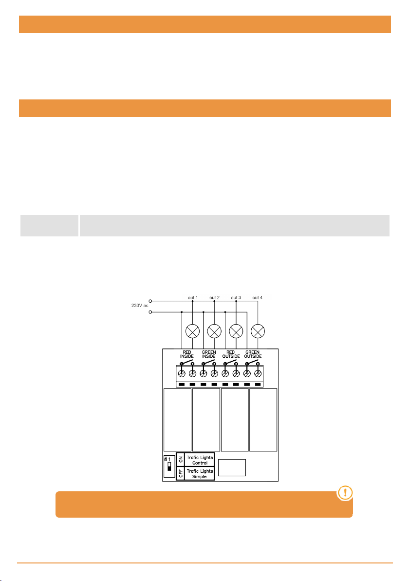
Traffic light card / Flash card (TL-CARD)
Traffic light card
This carries out two different functions accordingto the outlets:
Outlet 1 signal
Outlet 2
Outlet 3 and 4
Flash card
Of door movement t hrough the contact of a relay intermittently activated.
courtesy light contact; it operates during all the operating time plus 30 seconds. If option 5 of
the option switch is tur ned to OFF, it will carr y out the function of an electro-lock
traffic lights. Outlet 3 activates the red traffic light that works dur ing door movement. Outlet 4
activates the green traffic light that is only lit when the door isfullyopen
The traffic light selector carries out no function.
jcmtechnologies
11
Page 12

Troubleshooting
The following tableindicates the possible causes of operatingfailures inthe control panel t hrough the ERROR and SAFETY
LEDs.
Code ERROR led SAFETY led Description
255 on on Stop enabled
17 1 flash 1 flash Security band enabled
34 2 flashes 2 flashes Safety contact enabled
16 off 1 flash Excess consumption on closure
32 off 2 flashes Excessconsumption on opening
48 off 3 flashes Panelprogrammed by times
64 off 4 flashes Panelnot referenced or waiting to start reference search
1 1 flash off Security band not connected
2 2 flashes off Maximum current limit exceeded
3 3 flashes off End of run or programmed reference not reached
4 4 flashes off No encoder pulses
5 5 flashes off Panelprogrammed without references
6 6 flashes off Internal error
Use of the equipment
This equipment is designed to automate garage doors following the general description. It is not guaranteed for other uses.
The manufacturer reserves the right to modify equipment s pecifications w ithout priornotice.
Regulatory Data
EU Declaration of conformity
JCM TECHN OLOGIES, S.A. hereby declares that the product CONT-R15 complies with the relevant fundamental require-
ments of the RED Directive 2014/53/EU, as well as with the Machine Directive 2006/42/EC whenever its usageis foreseen;
and with the 2011/65/EU RoHS Directive.
See website www.jcm-tech.com/declarations/
JCM TECHN OLOGIES, SA
C/COSTA D'EN PARATGE, 6B
08500VIC (BARCELONA)
SPAIN
UM_3201356_CONT-R15_EN_Rev00
jcmtechnologies
12
 Loading...