

Page 1

OPERATOR'S MANUAL
MOBILE ELEVATING WORK PLATFORM
S1530E, S1930E, S2032E, S2046E,
S2632E, S2646E, S3246E, S4046E, S4550E
EN - 9831/3200 ISSUE 3 - 09/2017
THIS MANUAL SHOULD ALWAYS STAY WITH THE MACHINE
Page 2

Page 3

Foreword
The Operator's Manual
You and others can be killed or seriously injured
if you operate or maintain the machine without
first studying the Operator's Manual. You must
understand and follow the instructions in the
Operator's Manual. If you do not understand
anything, ask your employer or JCB dealer to
explain it.
OPERATOR'S
MANUAL
MOBILE ELEVATING WORK PLATFORM
S1530E, S1930E, S2032E,
S2046E, S2632E, S2646E,
S3246E, S4046E, S4550E
Do not operate the machine without an Operator's
Manual, or if there is anything on the machine you
do not understand.
Treat the Operator's Manual as part of the machine.
Keep it clean and in good condition. Replace the
Operator's Manual immediately if it is lost, damaged
or becomes unreadable.
Machine Delivery and Installation
Even if you have operated this type of equipment
before, it is very important that your new machines
operations and functions are explained to you by
a JCB Dealer Representative following delivery of
your new machine.
Following the installation you will know how to gain
maximum productivity and performance from your
new product.
Please contact your local JCB dealer if the
Installation Form (included in this manual) has not
yet been completed with you.
Your local JCB Dealer is
EN - 9831/3200 - ISSUE 3 - 09/2017
This manual contains original instructions, verified by
the manufacturer (or their authorized representative).
Copyright 2017 © JCB SERVICE
All rights reserved. No part of this publication may
be reproduced, stored in a retrieval system, or
transmitted in any form or by any other means,
electronic, mechanical, photocopying or otherwise,
without prior permission from JCB SERVICE.
www.jcb.com
Page 4

Notes:
9831/3200-3
Page 5

Table of Contents
Contents Page No.
Acronyms Glossary ........................................................................................................................................ iv
Introduction
About this Manual
Model and Serial Number ..................................................................................................................... 1
Using the Manual .................................................................................................................................. 1
Left-Hand Side, Right-Hand Side ......................................................................................................... 1
Cross References ................................................................................................................................. 2
Location of Manual ............................................................................................................................... 2
Safety
Safety - Yours and Others .................................................................................................................... 3
Safety Warnings .................................................................................................................................... 3
General Safety ...................................................................................................................................... 4
Clothing and Personal Protective Equipment (PPE) ............................................................................ 4
About the Product
Introduction
General .................................................................................................................................................. 5
Name and Address of the Manufacturer .............................................................................................. 5
Product Compliance .............................................................................................................................. 5
Description
General .................................................................................................................................................. 6
Intended Use ......................................................................................................................................... 6
Log Moving/Object Handling ................................................................................................................. 6
Danger Zone ......................................................................................................................................... 6
Main Component Locations .................................................................................................................. 7
Product and Component Identification
Machine ................................................................................................................................................. 9
Safety Labels
General ................................................................................................................................................ 10
Safety Label Identification ................................................................................................................... 10
Operation
Introduction
General ................................................................................................................................................ 15
Operating Safety
General ................................................................................................................................................ 16
Worksite Safety ................................................................................................................................... 17
Risk Assessment ................................................................................................................................ 17
Walk-Around Inspection
General ................................................................................................................................................ 19
Entering and Leaving the Operator Station
General ................................................................................................................................................ 20
Battery Isolator
General ................................................................................................................................................ 22
Stopping and Parking
General ................................................................................................................................................ 24
Getting the Machine Moving
General ................................................................................................................................................ 25
Slopes
General ................................................................................................................................................ 26
i 9831/3200-3 i
Page 6

Table of Contents
Driving on Slopes ............................................................................................................................... 26
Driving the Machine
General ................................................................................................................................................ 28
Operating Levers/Pedals
Control Layouts ................................................................................................................................... 29
Working with the Platform
General ................................................................................................................................................ 32
Extending and Retracting the Platform ............................................................................................... 35
Folding and Unfolding the Guardrails ................................................................................................. 35
Moving a Disabled Machine
General ................................................................................................................................................ 37
Lifting the Machine
General ................................................................................................................................................ 39
Transporting the Machine
General ................................................................................................................................................ 41
Loading the Machine onto the Transporting Vehicle/Trailer ............................................................... 41
Operating Environment
General ................................................................................................................................................ 43
Preservation and Storage
Storage
General ................................................................................................................................................ 45
Take out of Storage ............................................................................................................................ 45
Maintenance
Introduction
General ................................................................................................................................................ 47
Owner/Operator Support ..................................................................................................................... 47
Service/Maintenance Agreements ...................................................................................................... 48
Obtaining Spare Parts ........................................................................................................................ 48
Maintenance Safety
General ................................................................................................................................................ 49
Fluids and Lubricants ......................................................................................................................... 49
Batteries .............................................................................................................................................. 51
Maintenance Schedules
General ................................................................................................................................................ 55
How to Use the Maintenance Schedules ........................................................................................... 55
Maintenance Intervals ......................................................................................................................... 55
Pre-start Cold Checks, Service Points and Fluid Levels .................................................................... 56
Functional Tests and Final Inspection ................................................................................................ 57
Maintenance Positions
General ................................................................................................................................................ 58
Service Points
General ................................................................................................................................................ 61
Access Apertures
General ................................................................................................................................................ 63
Battery Cover ...................................................................................................................................... 63
Hydraulic Compartment Cover ........................................................................................................... 63
Body and Framework
General ............................................................................................................................................... 65
Safety Equipment
Check (Operation) ............................................................................................................................... 66
ii 9831/3200-3 ii
Page 7

Table of Contents
Brakes
Park Brake .......................................................................................................................................... 68
Steering System
General ............................................................................................................................................... 69
Tyres
General ............................................................................................................................................... 70
Hydraulic System
General ............................................................................................................................................... 71
Oil ........................................................................................................................................................ 74
Electrical System
General ............................................................................................................................................... 75
Battery ................................................................................................................................................. 75
Battery Isolator ................................................................................................................................... 80
Fuses .................................................................................................................................................. 80
Relays ................................................................................................................................................. 81
Technical Data
Introduction
General ................................................................................................................................................ 83
Static Dimensions
Dimensions .......................................................................................................................................... 84
Weights ............................................................................................................................................... 87
Performance Dimensions
Driving Performance ........................................................................................................................... 90
Noise Emissions
Noise Data .......................................................................................................................................... 94
Vibration Emissions
Vibration Data ..................................................................................................................................... 95
Fluids, Lubricants and Capacities
General ................................................................................................................................................ 96
Electrical System
General ................................................................................................................................................ 97
Fuses .................................................................................................................................................. 97
Hydraulic System
General ................................................................................................................................................ 99
Wheels and Tyres
General .............................................................................................................................................. 100
Fault-Finding
General .............................................................................................................................................. 101
Declaration of Conformity
General .............................................................................................................................................. 103
Data ................................................................................................................................................... 103
Warranty Information
Service Record Sheet ....................................................................................................................... 105
iii 9831/3200-3 iii
Page 8

Acronyms Glossary
AC Alternating Current
LCD Liquid Crystal Display
LED Light Emitting Diode
MECU Machine Electronic Control Unit
PPE Personal Protective Equipment
RCBO Residual current Circuit Breaker with Over current protection
USB Universal Serial Bus
Table of Contents
iv 9831/3200-3 iv
Page 9

About this Manual
Introduction
About this Manual
Model and Serial Number
This manual provides information for the following model(s) in the JCB machine range:
Model From: To:
2532501 2537500S1530E
2671002 2672000
2532501 2537500S1930E
2671002 2672000
2532501 2537500S2032E
2671002 2672000
2532501 2537500S2046E
2671002 2672000
2532501 2537500S2632E
2671002 2672000
2532501 2537500S2646E
2671002 2672000
S3246E 2532501 2537500
S4046E 2532501 2537500
S4550E 2533185 2537500
Introduction
Using the Manual
This operator's manual is arranged to give you a good understanding of the machine and its safe operation.
It also contains maintenance and technical data.
Read this manual from the front to the back before you use the machine for the first time, even if you have used
machines of a similar/same type before as the technical specification, systems and controls of the machine
may have changed. Particular attention must be given to all the safety aspects of operating and maintaining
the machine.
If there is anything you are not sure about, ask your JCB dealer or employer. Do not guess, you or others could
be killed or seriously injured.
The general and specific warnings in this section are repeated throughout the manual. Read all the safety
statements regularly, so you do not forget them. Remember that the best operators are the safest operators.
The illustrations in this manual are for guidance only. Where the machines are different, the text and or the
illustration will specify.
The manufacturer's policy is one of continuous improvement. The right to change the specification of the
machine without notice is reserved. No responsibility will be accepted for discrepancies which may occur
between specifications of the machine and the descriptions contained in this manual.
All of the optional equipment included in this manual may not be available in all territories
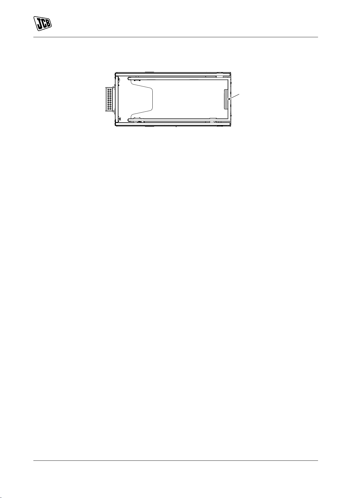
Left-Hand Side, Right-Hand Side
In this manual, 'left' and 'right' mean your left and right when you are stood in the platform facing the operator's
manual storage case.
1 9831/3200-3 1
Page 10
Introduction
A
B
C
About this Manual
Figure 1.
A Left B Right
C Operator's manual storage case
Cross References
In this manual, cross references are made by presenting the subject title in blue (electronic copy only). The
number of the page upon which the subject begins is indicated within the brackets. For example: Refer to:
Cross References (Page 2).
Location of Manual
The operator's manual is located in a storage case at one end of the platform. The manual should always be
returned to its case after use. Refer to: Main Component Locations (Page 7).
2 9831/3200-3 2
Page 11

Introduction
Safety
Safety
Safety - Yours and Others
All machinery can be hazardous. When a machine is correctly operated and maintained, it is a safe machine
to work with. When it is carelessly operated or poorly maintained it can become a danger to you (the operator)
and others.
In this manual and on the machine you will find warning messages, read and understand them. They inform
you of potential hazards and how to avoid them. If you do not fully understand the warning messages, ask your
employer or JCB dealer to explain them.
Safety is not just a matter of responding to the warnings. All the time you are working on or with the machine
you must be thinking of what hazards there might be and how to avoid them.
Do not work with the machine until you are sure that you can control it.
Do not start any work until you are sure that you and those around you will be safe.
If you are not sure of anything, about the machine or the work, ask someone who knows. Do not assume
anything.
Remember:
• Be careful
• Be alert
• Be safe.
Safety Warnings
In this manual and on the machine, there are safety notices. Each notice starts with a signal word. The signal
word meanings are given below.
The signal word 'DANGER' indicates a hazardous situation which, if not avoided, will result in death or serious
injury.
The signal word 'WARNING' indicates a hazardous situation which, if not avoided, could result in death or
serious injury.
The signal word 'CAUTION' indicates a hazardous situation which, if not avoided, could result in minor or
moderate injury.
The signal word 'Notice' indicates a hazardous situation which, if not avoided, could result in machine damage.
The safety alert system (shown) also helps to identify important safety messages in this manual and on the
machine. When you see this symbol, be alert, your safety is involved, carefully read the message that follows,
and inform other operators.
Figure 2. The safety alert system
3 9831/3200-3 3
Page 12

Introduction
Safety
General Safety
Training
To operate the machine safely you must know the machine and have the skill to use it. You must abide by
all relevant laws, health and safety regulations that apply to the country you are operating in. The operator's
manual instructs you on the machine, its controls and its safe operation; it is not a training manual. If you are a
new operator, get yourself trained in the skills of using a machine before trying to work with it. If you don't, you
will not do your job well, and you will be a danger to yourself and others. In some markets and for work on certain
jobsites you may be required to have been trained and assessed in accordance with an operator competence
scheme. Make sure that you and your machine comply with relevant local laws and jobsite requirements - it
is your responsibility.
Care and Alertness
All the time you are working with or on the machine, take care and stay alert. Always be careful. Always be
alert for hazards.
Clothing
You can be injured if you do not wear the correct clothing. Loose clothing can get caught in the machinery.
Keep cuffs fastened. Do not wear a necktie or scarf. Keep long hair restrained. Remove rings, watches and
personal jewellery.
Alcohol and Drugs
It is extremely dangerous to operate machinery when under the influence of alcohol or drugs. Do not consume
alcoholic drinks or take drugs before or while operating the machine or attachments. Be aware of medicines
which can cause drowsiness.
Feeling Unwell
Do not attempt to operate the machine if you are feeling unwell. By doing so you could be a danger to yourself
and those you work with.
Mobile Phones
Switch off your mobile phone before entering an area with a potentially explosive atmosphere. Sparks in such
an area could cause an explosion or fire resulting in death or serious injury.
Lifting Equipment
You can be injured if you use incorrect or faulty lifting equipment. You must identify the weight of the item to
be lifted then choose lifting equipment that is strong enough and suitable for the job. Make sure that lifting
equipment is in good condition and complies with all local regulations.
Raised Machine
Never position yourself or any part of your body inside the raised scissor pack which is not correctly supported.
If the machine moves unexpectedly you could become trapped and suffer serious injury or be killed.
Lightning
Lightning can kill you. Do not use the machine if there is lightning in your area.
Machine Modifications
This machine is manufactured in compliance with prevailing legislative requirements. It must not be altered in
any way which could affect or invalidate its compliance. For advice consult your JCB dealer.
Clothing and Personal Protective Equipment (PPE)
Do not wear loose clothing or jewellery that can get caught on controls or moving parts. Wear protective clothing
and personal safety equipment issued or called for by the job conditions, local regulations or as specified by
your employer.
4 9831/3200-3 4
Page 13

About the Product
Introduction
About the Product
Introduction
General
Before you start using the machine, you must know how the machine operates. Use this part of the manual
to identify each control lever, switch, gauge, button and pedal. Do not guess, if there is anything you do not
understand, ask your JCB dealer.
Name and Address of the Manufacturer
JCB Access Limited, Lakeside Works, Rocester, Uttoxeter, United Kingdom, ST14 5JP
Product Compliance
Your JCB product was designed to comply with the laws and regulations applicable at the time of its manufacture
for the market in which it was first sold. In many markets, laws and regulations exist that require the owner to
maintain the product at a level of compliance relevant to the product when first produced. Even in the absence
of defined requirements for the product owner, JCB recommend that the product compliance be maintained
to ensure safety of the operator and exposed persons and to ensure the correct environmental performance.
Your product must not be altered in any way which could affect or invalidate any of these requirements. For
advice consult your JCB dealer.
For its compliance as a new product, your JCB and some of its components may bear approval numbers
and marking's, and may have been supplied with a Declaration/Certificate of Conformity. These marking's and
documents are relevant only for the country/region in which the product was first sold to the extent that the
laws and regulations required them.
Re-sales and import/export of products across territories with different laws and regulations can cause new
requirements to become relevant for which the product was not originally designed or specified. In some cases,
pre owned products irrespective of their age are considered new for the purposes of compliance and may be
required to meet the latest requirements which could present an insurmountable barrier to their sale/use.
Despite the presence of any compliance related marking's on the product and components, you should not
assume that compliance in a new market will be possible. In many cases it is the person responsible for import
of a pre owned product into a market that becomes responsible for compliance and who is also considered
the manufacturer.
JCB may be unable to support any product compliance related enquiry for a product which has been moved out
of the legislative country/region where it was first sold, and in particular where a product specification change
or additional certification would have been required in order for the product to be in compliance.
5 9831/3200-3 5
Page 14

About the Product
Description
Description
General
This machine is a self propelled aerial work platform on the top of an elevating scissor arm mechanism.
Intended Use
The machine is intended to lift the personnel with their tools and position them at a level of working height.
The machine can be used to reach areas located above machinery or equipment positioned at ground level
by use of the extending platform.
The machine is intended to be used in normal conditions for the applications and in the environmental conditions
as described in this manual. Use in any other way not described in the manual is considered contrary to intended
use of this machine.
The machine is not intended for use in mining and quarrying applications, in demolition activities, forestry, any
use underground, or in any kind of explosive atmosphere. This is not an exhaustive list. For any activity not
described here, it is recommended that a risk assessment must be done prior to operation.
If the machine is to be used in applications where there is a high silica concentration, risk due to materials
containing asbestos or similar hazards, additional protective measures such as the use of PPE (Personal
Protective Equipment) may be required.
The machine should not be operated by any person who does not have an appropriate level of qualification,
training or experience of use of this type of machine.
Prior to use of the machine, its suitability (size, performance, specification etc.) should be considered with
regards to the intended application and any relevant hazards that may exist. Contact your JCB dealer for
support in determining the appropriate JCB machine, attachment and any optional equipment that is suitable
for the application and environment.
Log Moving/Object Handling
Do not use the machine to move or handle logs or other objects. You could cause serious injury to yourself
and damage to the machine. Do not use the machine as a crane. Do not overload the platform with tools or
equipment. Refer to: Technical Data (Page 83). For more information, contact your JCB dealer.
Danger Zone
The danger zone is any zone within and/or around the machinery in which a person is subject to a risk to their
health or safety. During operation of the machine, keep all persons out of the danger zone. Persons in the
danger zone could be injured.
Before you do a maintenance task, make the product safe. Refer to: Maintenance Positions (Page 58).
6 9831/3200-3 6
Page 15
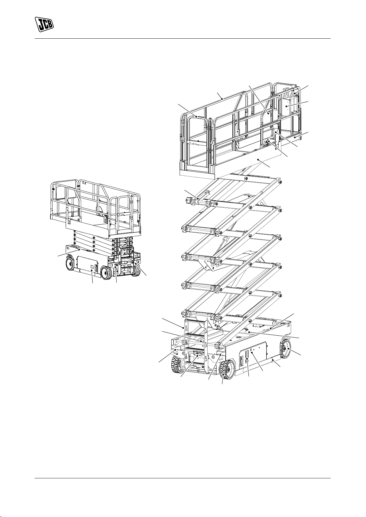
Main Component Locations
K
W
U
T
S
R
K
L
M
N
Q
P
S
V
F
J
G
H
A
B
C
D
E
X
Y
Z
About the Product
Description
Figure 3.
A Gate B Guardrail
C Harness fastening point D Platform control panel
E Operator's Manual F Platform extension
G AC (Alternating Current) Power socket (option) H Extension platform pedal
J Main platform K Warning lights
L Tilt sensor M Front wheel (steering)
N Pot hole protection plate P MECU (Machine Electronic Control Unit) display
Q Ground controller R Rear wheel
S Lift point/forklift position T Manual release valve and emergency lowering
U Pot hole activation plungers V Ladder
W Safety strut X Battery charger
7 9831/3200-3 7
handle
Page 16

Y Charging plug Z Power to platform plug
About the Product
Description
8 9831/3200-3 8
Page 17
Product and Component Identification
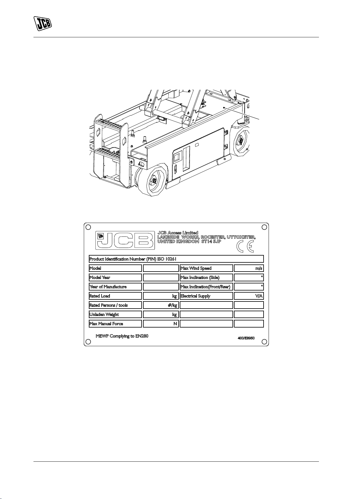
A
Machine
Your machine has an identification plate as shown. Refer to Figure 4.
Figure 4.
About the Product
Product and Component Identification
A Machine identification plate location
Figure 5. Machine Identification Plate
9 9831/3200-3 9
Page 18
About the Product
F
F
E
G
H
J
J
A
B
D
C
E
Safety Labels
Safety Labels
General
WARNING Safety labels on the machine warn you of particular hazards. You can be injured if you do not
obey the safety instructions shown.
The safety labels are strategically placed around the machine to remind you of possible hazards.
If you need eye-glasses for reading, make sure you wear them when reading the safety labels. Do not overstretch or put yourself in dangerous positions to read the safety labels. If you do not understand the hazard
shown on the safety label, then refer to Safety Label Identification.
Keep all of the safety labels clean and readable. Replace a lost or damaged safety label. Make sure the
replacement parts include the safety labels where necessary. Each safety label has a part number printed on
it, use this number to order a new safety label from your JCB dealer.
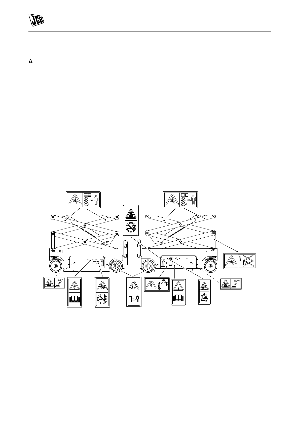
Safety Label Identification
For: S1530E, S1930E .............................................................................................................. Page 10
For: S2032E, S2632E, S4550E ............................................................................................... Page 12
For: S2046E, S2646E, S3246E, S4046E ................................................................................. Page 13
(For: S1530E, S1930E)
Figure 6.
10 9831/3200-3 10
Page 19
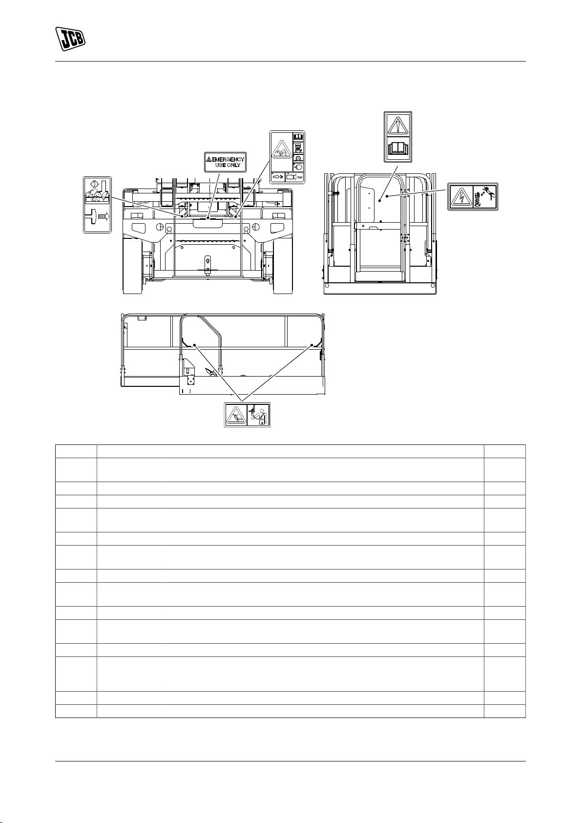
Figure 7.
P
B
K
L
M
R
About the Product
Safety Labels
Table 1. Safety Labels
Item Part No. Description Qty.
A 400/G0761 Crush hazard (to feet). Keep a safe distance. The attachment may roll
forward when released.
B 400/D2107 Electrical hazard. Stay a safe distance away from power lines. 2
C 817/70092 Warning. Read the Operator’s Manual before you operate the machine. 1
D 400/G0762 Pressure hazard. Stop the machine, remove the ignition key and consult
service manual before carrying out any servicing and maintenance work.
E 400/G0767 Explosion hazard. Remove the sources of ignition. 2
F 400/D0831 Warning. Crush hazard. Keep a safe distance from scissor pack/
G 400/G6092 Electrical hazard. Read operator’s manual. 1
H 400/D2141 Warning. Engage safety strut before carrying out maintenance within the
J 332/P7128 Burns to fingers and hands. Stay a safe distance away. 2
K 400/G3529 Warning. Emergency descent control. Pull lever to lower the platform in
L 400/D2576 Warning. Item for emergency use only. 2
M 400/D2979 Warning. Danger of uncontrolled machine movement. Platform to be in
P 400/D1430 Wear safety harness. 4
R 400/G0705 Warning. Read operator’s manual before operating machine. 1
mechanism.
scissor pack.
the event that the operator is incapacitated.
fully lowered position. Use wheel chocks. To release brakes, push valve
and pump lever.
4
1
4
1
1
1
11 9831/3200-3 11
Page 20
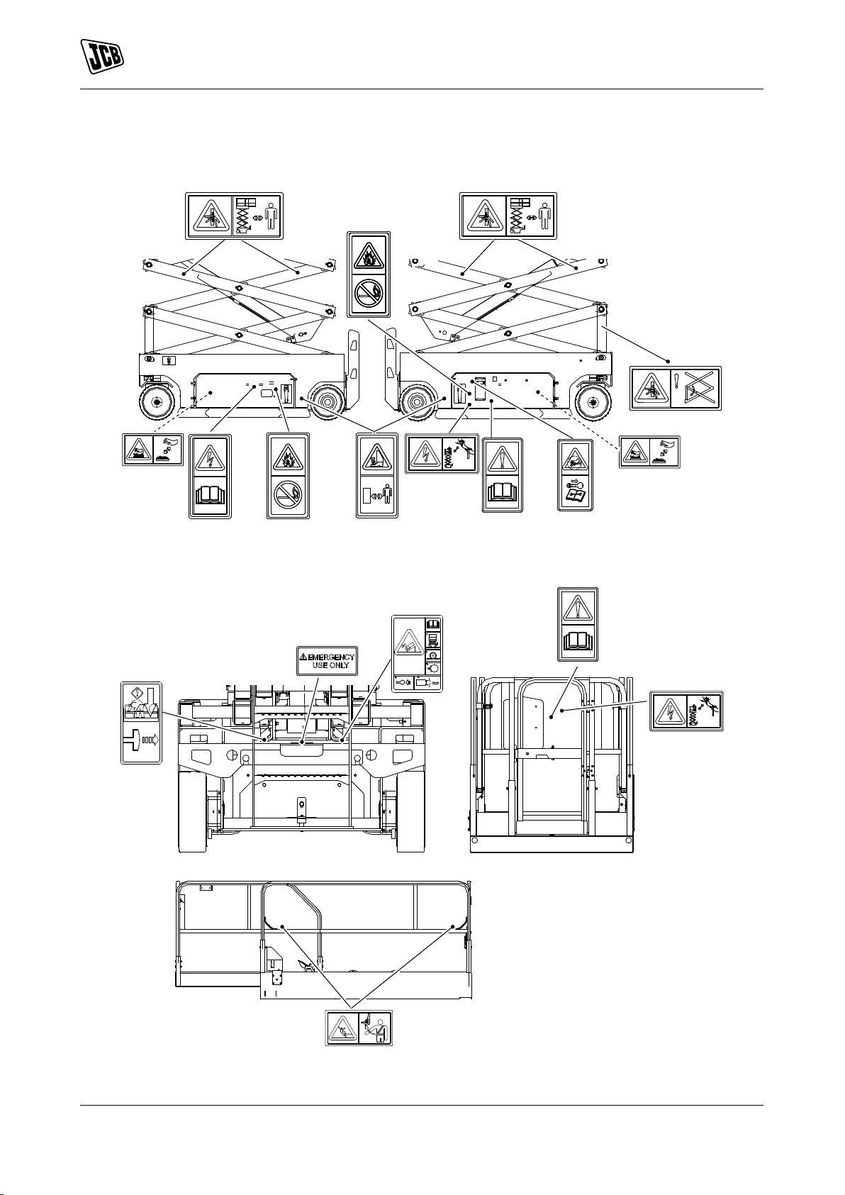
(For: S2032E, S2632E, S4550E)
F
F
E
G
H
J
J
A
B
D
C
E
P
B
K
L
M
R
About the Product
Safety Labels
Figure 8.
Figure 9.
12 9831/3200-3 12
Page 21
About the Product
F
F
E
G
H
J
J
A
B
D
C
E
Safety Labels
Table 2. Safety Labels
Item Part No. Description Qty.
A 332/P7135 Crush hazard (to feet). Keep a safe distance. The attachment may roll
forward when released.
B 400/D2107 Electrical hazard. Stay a safe distance away from power lines. 2
C 817/70092 Warning. Read the Operator’s Manual before you operate the machine. 1
D 817/70002 Pressure hazard. Stop the engine, remove the starter key and consult the
Service Manual before you complete any service or maintenance work.
E 817/70042 Explosion hazard. Remove sources of ignition. 2
F 400/D0831 Warning. Crush hazard. Keep a safe distance from scissor pack/
mechanism.
G 817/70032 Electrical hazard. Read the Operator’s Manual. 1
H 400/D2141 Warning. Engage safety strut before carrying out maintenance within the
scissor pack.
J 332/P7128 Burns to fingers and hands. Stay a safe distance away. 2
K 400/G3529 Warning. Emergency descent control. Pull lever to lower the platform in
the event that the operator is incapacitated.
L 400/D2576 Warning. Item for emergency use only. 2
M 400/D2979 Warning. Danger of uncontrolled machine movement. Platform to be in
fully lowered position. Use wheel chocks. To release brakes, push valve
and pump lever.
P 400/D1430 Wear safety harness. 4
R 400/G0705 Warning. Read operator’s manual before operating machine. 1
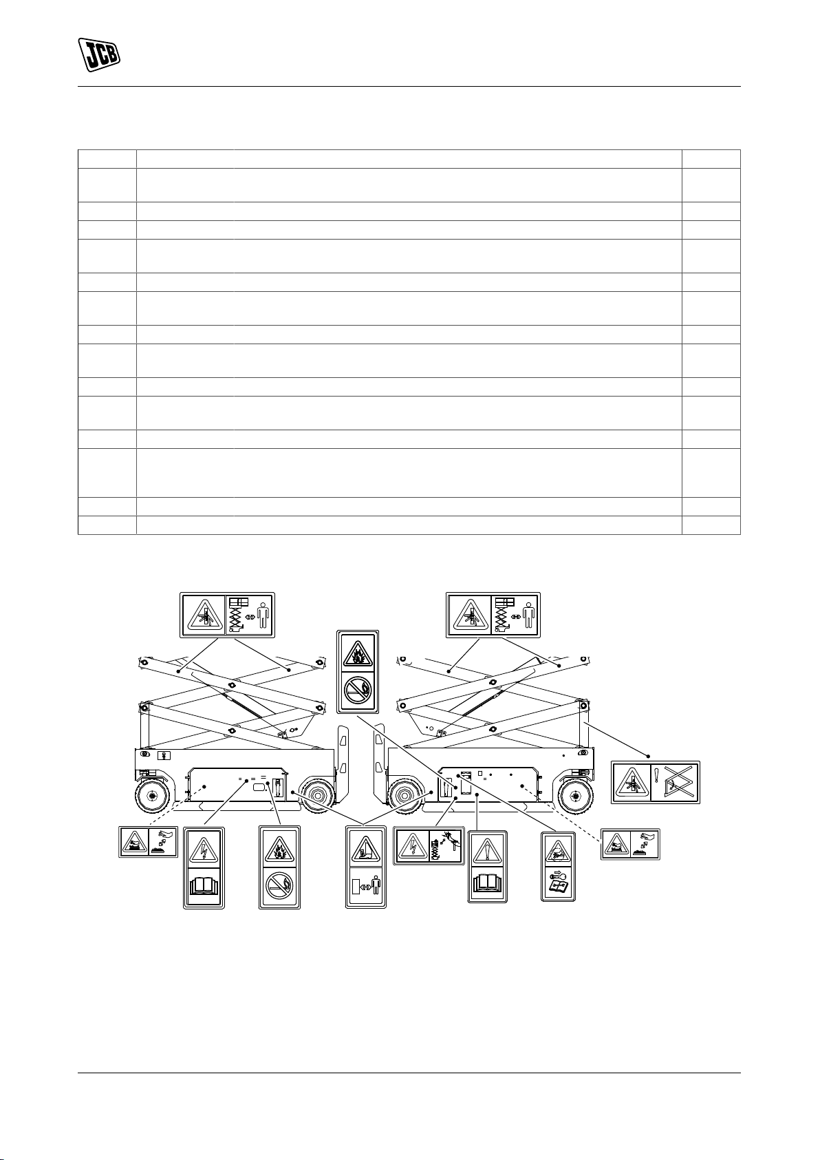
(For: S2046E, S2646E, S3246E, S4046E)
4
1
4
1
1
1
Figure 10.
13 9831/3200-3 13
Page 22

Figure 11.
P
B
K
L
M
R
About the Product
Safety Labels
Table 3. Safety Labels
Item Part No. Description Qty.
A 332/P7135 Crush hazard (to feet). Keep a safe distance. The attachment may roll
forward when released.
B 400/D2107 Electrical hazard. Stay a safe distance away from power lines. 2
C 817/70092 Warning. Read the Operator’s Manual before you operate the machine. 2
D 817/70002 Pressure hazard. Stop the engine, remove the starter key and consult the
Service Manual before you complete any service or maintenance work.
E 817/70042 Explosion hazard. Remove sources of ignition. 2
F 400/D0831 Warning. Crush hazard. Keep a safe distance from scissor pack/
G 817/70032 Electrical hazard. Read the Operator’s Manual. 1
H 400/D2141 Warning. Engage safety strut before carrying out maintenance within the
J 332/P7128 Burns to fingers and hands. Stay a safe distance away. 2
K 400/G3529 Warning. Emergency descent control. Pull lever to lower the platform in
L 400/D2576 Warning. Item for emergency use only. 2
M 400/D2979 Warning. Danger of uncontrolled machine movement. Platform to be in
P 400/D1430 Wear safety harness. 4
mechanism.
scissor pack.
the event that the operator is incapacitated.
fully lowered position. Use wheel chocks. To release brakes, push valve
and pump lever.
4
1
4
1
1
1
14 9831/3200-3 14
Page 23

Operation
Introduction
Operation
Introduction
General
The aim of this part of the manual is to guide the operator step-by-step through the task of learning how to
operate the machine efficiently and safely. Read the Operation section through from beginning to end.
The operator must always be aware of events happening in or around the machine. Safety must always be the
most important factor when you operate the machine.
When you understand the operating controls, gauges and switches, practice using them. Drive the machine in
an open space, clear of people. Get to know the 'feel' of the machine and its driving controls.
Do not rush the job of learning, make sure you fully understand everything in the Operation section. Take your
time and work efficiently and safely.
Remember:
• Be careful.
• Be alert.
• Be safe.
15 9831/3200-3 15
Page 24

Operation
Operating Safety
Operating Safety
General
Training
Make sure that you have had adequate training and that you are confident in your ability to operate the machine
safely before you use it. Practice using the machine and its attachments until you are completely familiar with
the controls and what they do. With a careful, well trained and experienced operator, your machine is a safe
and efficient machine. With an inexperienced or careless operator, it can be dangerous. Do not put your life,
or the lives of others, at risk by using the machine irresponsibly. Before you start to work, tell your colleagues
what you will be doing and where you will be working. On a busy site, use a signalman.
Before doing any job not covered in this manual, find out the correct procedure. Your local JCB distributor will
be glad to advise you.
Machine Condition
A defective machine can injure you or others. Do not operate a machine which is defective or has missing
parts. Make sure the maintenance procedures in this manual are completed before using the machine.
Machine Limits
Operating the machine beyond its design limits can damage the machine, it can also be dangerous. Do
not operate the machine outside its limits. Do not try to upgrade the machine performance with unapproved
modifications or additional equipment.
Communications
Bad communications can cause accidents. Keep people around you informed of what you will be doing. If you
will be working with other people, make sure any hand signals that may be used are understood by everybody.
Worksites can be noisy, do not rely on spoken commands.
Parking
An incorrectly parked machine can move without an operator. Follow the instructions in the Operator's Manual
to park the machine correctly.
Banks and Trenches
Banked material and trenches can collapse. Do not work or drive too close to banks and trenches where there
is danger of collapse.
Safety Barriers
Unguarded machines in public places can be dangerous. In public places, or where your visibility is reduced,
place barriers around the work area to keep people away.
Sparks
Explosions and fire can be caused by sparks from the electrical system. Do not use the machine in closed
areas where there is flammable material, vapour or dust.
Regulations
Obey all laws, worksite and local regulations which affect you and your machine.
Electrical Power Cables
You could be electrocuted or badly burned if you get the machine or its attachments too close to electrical
power cables.
You are strongly advised to make sure that the safety arrangements on site comply with the local laws and
regulations concerning work near electric power lines.
Before you start using the machine, check with your electricity supplier if there are any buried power cables
on the site.
There is a minimum clearance required for working beneath overhead power cables. You must obtain details
from your local electricity supplier.
Machine Safety
Stop work at once if a fault develops. Abnormal sounds and smells can be signs of trouble. Examine and repair
before resuming work.
16 9831/3200-3 16
Page 25

Operation
Operating Safety
Travelling at High Speeds
Travelling at high speeds can cause accidents. Always travel at a safe speed to suit working conditions.
Confined Areas
Pay extra attention to proximity hazards when operating in confined areas. Proximity hazards include buildings,
traffic and bystanders.
Safe Working Loads
Overloading the machine can damage it and make it unstable. Study the specifications in the Operator's Manual
before using the machine.
Lightning
If there is lightning, stay away from the machine and do not use the machine. If you are on the machine, exit
the machine and get to safety. Do not attempt to mount or enter the machine.
If the machine is struck by lightning do not use the machine until it has been checked for damage and
malfunction by trained personnel.
Worksite Safety
"Workplace Inspection" will help operators to determine whether the workplace is suitable for operation.
Operators must inspect the workplace before they move machines there. It is the operator's responsibility to
understand and keep in mind the hazards in the workplace, He/she shall pay attention and avoid these problems
when move, install and operate the machine. Check for hazards such as but not limited to:
• Drop-offs, or potholes including those concealed by water mud, etc.
• Slopes.
• Bumps and floor obstructions.
• Debris.
• Over head obstructions and electrical conductors.
• Hazardous locations and atmospheres.
• Inadequate surface and support to withstand all load forces imposed by the platform in all operating
configurations.
• Wind and weather conditions.
• Presence of unauthorized persons.
• Other possible unsafe conditions.
Risk Assessment
It is the responsibility of the competent people that plan the work and operate the machine to make a judgement
about the safe use of the machine, they must take into account the specific application and conditions of use
at the time.
It is essential that a risk assessment of the work to be done is completed and that the operator obeys any
safety precautions that the assessment identifies.
If you are unsure of the suitability of the machine for a specific task, contact your JCB dealer who will be
pleased to advise you.
The following considerations are intended as suggestions of some of the factors to be taken into account when
a risk assessment is made. Other factors may need to be considered.
A good risk assessment depends on the training and experience of the operator. Do not put your life or the
lives of others at risk.
Personnel
• Are all persons who will take part in the operation sufficiently trained, experienced and competent? Are
they fit and sufficiently rested? A sick or tired operator is a dangerous operator.
• Is supervision needed? Is the supervisor sufficiently trained and experienced?
17 9831/3200-3 17
Page 26

Operation
Operating Safety
• As well as the machine operator, are any assistants or lookouts needed?
The Machine
• Is it in good working order?
• Have any reported defects been corrected?
• Have the daily checks been carried out?
• Are the tyres in good condition?
• Is the battery sufficiently charged to complete the job?
Working Area
• Is it level?
• Is the ground solid? Will it support the weight of the machine when loaded?
• How rough is the ground? Are there any sharp projections which could cause damage, particularly to
the tyres?
• Are there any obstacles or hazards in the area, for example, debris, excavations, manhole covers, power
lines?
• Is the space sufficient for safe manoeuvring?
• Are any other machines or persons likely to be in or to enter the area while operations are in progress?
The Route to be Travelled
• How solid is the ground, will it provide sufficient traction and braking? Soft ground will affect the stability
of the machine and this must be taken into account.
• How steep are any slopes, up/down/across? A cross slope is particularly hazardous, is it possible to detour
to avoid them?
Weather
• How windy is it? High wind will adversely affect the stability of a loaded machine.
• Is it raining or is rain likely? The ground that was solid and smooth when dry will become uneven and
slippery when wet, and it will not give the same conditions for traction, steering or braking.
Emergency Plan
Make sure that emergency rescue plan is in place and understood by those involved when operating the
machine from platform controller at height.
18 9831/3200-3 18
Page 27

Operation
Walk-Around Inspection
Walk-Around Inspection
General
The following checks must be made each time you return to the machine after leaving it for any period of time.
We advise you also to stop the machine occasionally during long work sessions and do the checks again.
All these checks concern the serviceability of the machine. Some concern your safety. Get your service engineer
to check and correct any defects.
1. Check for cleanliness.
1.1. Remove dirt and debris, especially from around the linkages, rams, pivot points.
1.2. Make sure the platform floor and handrails are clean and dry.
1.3. Clean all of the safety and instructional labels. Replace any label that is missing or cannot be read.
2. Check for damage.
2.1. Examine the machine generally for damaged and missing parts.
2.2. Make sure that all of the fasteners and pivot pins are correctly installed.
2.3. Check the operation of the platform side rails.
2.4. Check the condition of the tyres.
2.5. Check for leaks
3. Make sure that all of the access panels are closed correctly.
3.1. If access panels are installed with locks, we recommend that you lock them to prevent theft or
tampering.
4. Check the operation of all controls.
5. Check the operator's manual is in good condition and is kept in the operator's manual storage compartment.
6. Check the level of the hydraulic fluid and for leaks.
7. Check the visual condition of the batteries, cables and wiring.
8. Check the operation of the safety equipment.
Refer to: Check (Operation) (Page 66).
19 9831/3200-3 19
Page 28

Operation
Entering and Leaving the Operator Station
Entering and Leaving the Operator Station
General
CAUTION If the guardrails have been folded down, use extreme caution when entering and leaving the
operator station. Do not operate the controls from the platform when the guard rails are folded.
CAUTION Entering or leaving the operator station must only be made where steps and handrails are
provided. Always face the machine when entering and leaving. Make sure the step(s), handrails and your
boot soles are clean and dry. Do not jump from the machine. Do not use the machine controls as handholds,
use the handrails.
Make sure the machine is stopped, correctly parked and fully stowed before entering or leaving the platform.
Refer to: Stopping and Parking (Page 24).
When entering and leaving the platform always maintain three points of contact with the guardrails and step.
Do not use the machine controls as handholds.
Entering the Platform
1. Hold the two guardrails, then use the steps to climb up to the platform. Refer to Figure 12.
2. Depress the lever and open the platform door.
3. Step into the platform.
4. Close the platform door and make sure it latches correctly.
Leaving the Platform
1. Park the machine on solid (slabbed or paved), level ground.
2. Depress the lever and open the platform door.
3. Hold both of the guardrails and step backwards out of the platform onto the steps.
4. Close the platform door and make sure it latches correctly.
5. Use the steps to climb down backwards onto the ground.
20 9831/3200-3 20
Page 29
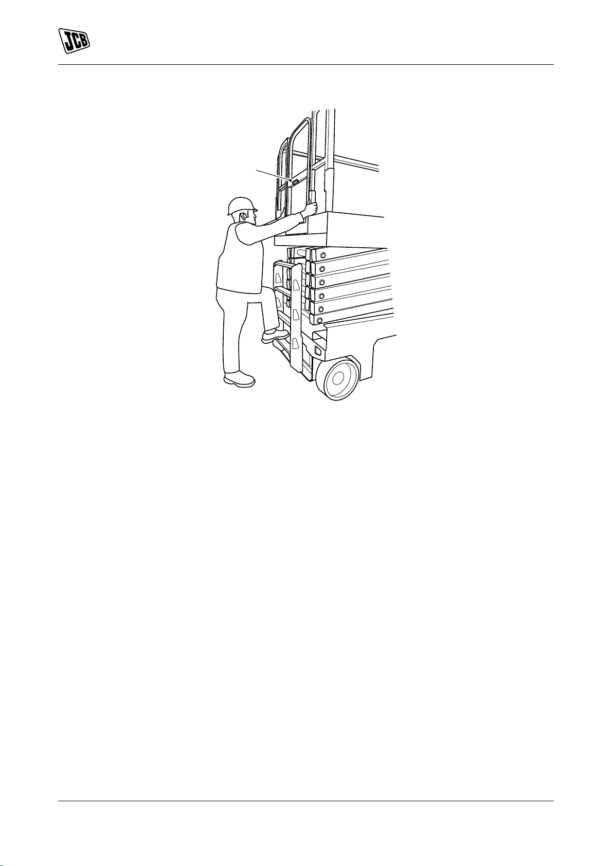
Figure 12.
A
Operation
Entering and Leaving the Operator Station
A Lever
21 9831/3200-3 21
Page 30
Battery Isolator
A
General
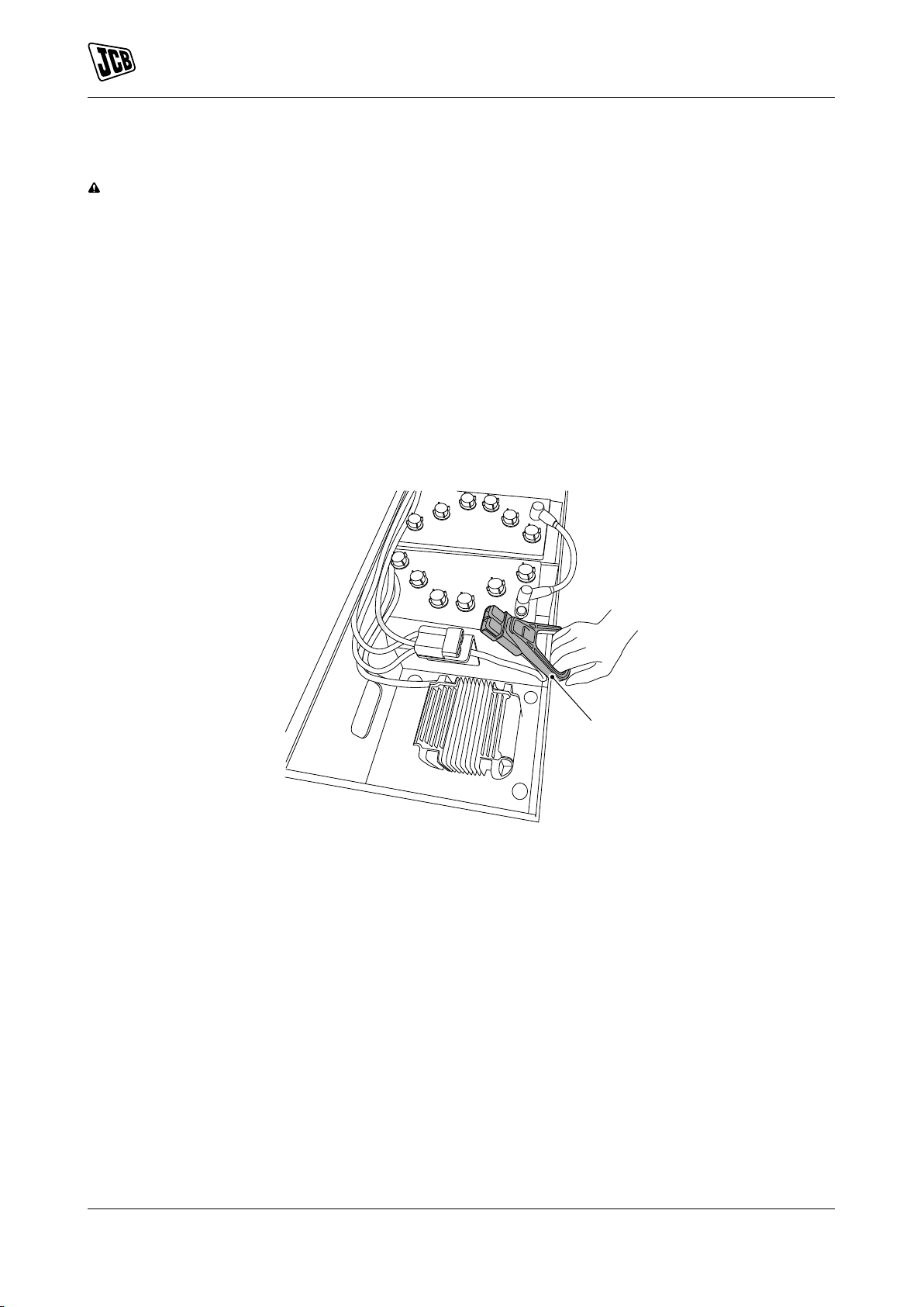
WARNING The batteries remain live even when the isolator key is removed.
Disconnect the Machine Electrics:
1. Turn the key switch to the off position.
2. Get access to the battery isolator.
Refer to: Access Apertures (Page 63).
3. Disconnect the battery isolator by pulling handle. Refer to Figure 13.
Connect the Machine Electrics:
1. Make sure the key switch is at off position.
2. Connect the battery isolator.
Figure 13. Lead Acid Battery
Operation
Battery Isolator
A Battery isolator
22 9831/3200-3 22
Page 31

A
A Battery isolator
Operation
Battery Isolator
Figure 14. Lithium Iron Phosphate Battery
23 9831/3200-3 23
Page 32

Operation
Stopping and Parking
Stopping and Parking
General
This machine has brakes installed on the rear wheels only. The brakes installed on this machine are park brake
only, there are no dynamic brakes installed.
The brake will release automatically during travel, the brake will not release during lifting.
1. Select a safe place to stop where the ground is firm and level such as slabbed or paved surface, where
the machine will not cause an obstruction and away from heavy traffic.
2. Lower the platform.
3. Turn the key switch to the off position. Remove the key to avoid unauthorized use.
3.1. Before switching off the machine check the battery level. If necessary, put the machine on charge to
ensure that the battery is fully charged for the next time the machine is used.
Brake Operational Limits
The machine brakes are capable of stopping the machine at its maximum speed on the maximum gradients
as stated in this manual.
It is recommended that the machine is not parked or left unattended on slopes greater than those specified
in this manual. It is the responsibility of the operator to assess the ground and atmospheric conditions before
using or parking the machine on gradients.
The machine must be immediately taken out of service until corrected if the brakes do not operate within
specifications or performance requirements as defined in this manual or any other in-service, periodic or postmaintenance brake verification.
24 9831/3200-3 24
Page 33

Operation
Getting the Machine Moving
Getting the Machine Moving
General
WARNING Watch for obstructions around machine and overhead when driving. Check clearance above, to
sides, at bottom of machine when lifting or lowering the platform.
WARNING Keep hands and arms out of the path of the scissor arms when lowering the platform.
WARNING Do not use the platform controller to release the platform when it is stuck, snagged or caught.
In this case, use the ground controller only when there are no persons on the platform.
CAUTION Do not raise platform with the guardrails folded down. The guardrails must be in their upright
positions and properly secured when raising the platform.
Raising and Lowering the Platform
Refer to: Operating Levers/Pedals (Page 29).
Operation from the Ground
1. Turn the key switch to ground control.
2. Make sure the ground and platform emergency stop buttons are pulled out.
3. Move the platform raising/lowering toggle switch either up or down. Move up to raise the platform. Move
down to lower the platform.
4. When lowering the platform the platform will stop part way down for safety. Release the toggle switch
and check there are no obstructions in the scissors. Move the toggle switch down again to fully lower the
platform. There is an intentional delay periods of 3 seconds after the stop and 1.5 seconds after the toggle
switch is pressed during lowering.
Operation from the Platform
1. Turn the key switch to platform control.
2. Make sure the ground and platform emergency stop buttons are pulled out.
3. Press the raise/lower mode button on the platform controller. The button should illuminate.
4. Press and hold the enable switch.
5. Move the joystick forwards or backwards. Check the arrow colours on the joystick with the operating
direction. Move forwards to lower the platform. Move backwards to raise the platform.
Operation in Raised Position
The automatic pothole protection system will fold down and drive speed is reduced when the platform raised.
25 9831/3200-3 25
Page 34

Operation
B
A
Slopes
Slopes
General
WARNING Make sure that you have been trained and are familiar with the use of machines on slopes, and
understand the adverse affects that slopes and site conditions can have on stability. Never use the machine
on a slope if you do not understand the recommended practices for the use of machines in such applications.
There are a number of factors which can adversely affect the stability of the machine and the safety of the
machine and operator when used on a slope.
It is essential that a risk assessment of the work to be done is completed and that the operator complies with
any safety precautions that the assessment identifies.
Driving on Slopes
WARNING If the tilt indicator warning light/alarm is activated while driving with platform raised, lower the
platform and drive to a smooth firm level surface.
While driving on slopes with the platform fully stowed make sure that the front/back and side slope does not
exceed the rated gradient for the machine. Refer to: Performance Dimensions (Page 90).
Figure 15.
A Front/back slope B Side slope
While driving on slopes with the platform raised make sure that front/back slope and side slope does not exceed
the angles specified.
Front/back slope 3°
Side slope 1.5°
26 9831/3200-3 26
Page 35

Figure 16.
B
A
A Front/back slope B Side slope
Operation
Slopes
27 9831/3200-3 27
Page 36

Operation
Driving the Machine
Driving the Machine
General
Operation from the Ground
1. Drive and steer functions are not available on the ground controller.
Operation from the Platform
Machine travel speed is restricted when the platform is raised.
1. Turn the key switch to platform control.
Refer to: Control Layouts (Page 29).
2. Make sure the ground and platform emergency stop buttons are pulled out.
3. Press the drive mode button. The button should illuminate. Always check that the machine is in the correct
mode before moving the joystick.
4. Press and hold the enable switch.
5. Slowly move the joystick forwards or backwards. Move forwards to move the machine forwards. Move
backwards to move the machine backwards.
Drive Speed
There are two drive speeds available when the machine is stationary. Press the speed button to switch between
high speed and low speed. When the light is illuminated slow speed is enabled. When the light is extinguished
high speed is enabled. Slow speed is activated when the platform is raised. Always check that the machine is
in the correct drive speed before moving the joystick, especially after lowering the platform.
Steering
Press and hold the enable switch. Press the steering switch left or right to change the steering direction of
the steering wheels.
28 9831/3200-3 28
Page 37
Operation
E
F
AA
B
C
D
Operating Levers/Pedals
Operating Levers/Pedals
Control Layouts
CAUTION Keep the machine controls clean and dry. Your hands and feet could slide off slippery controls.
If that happens you could lose control of the machine.
Ground Controller
WARNING Do not operate the machine with the ground controller when there are personnel in the platform
except in an emergency.
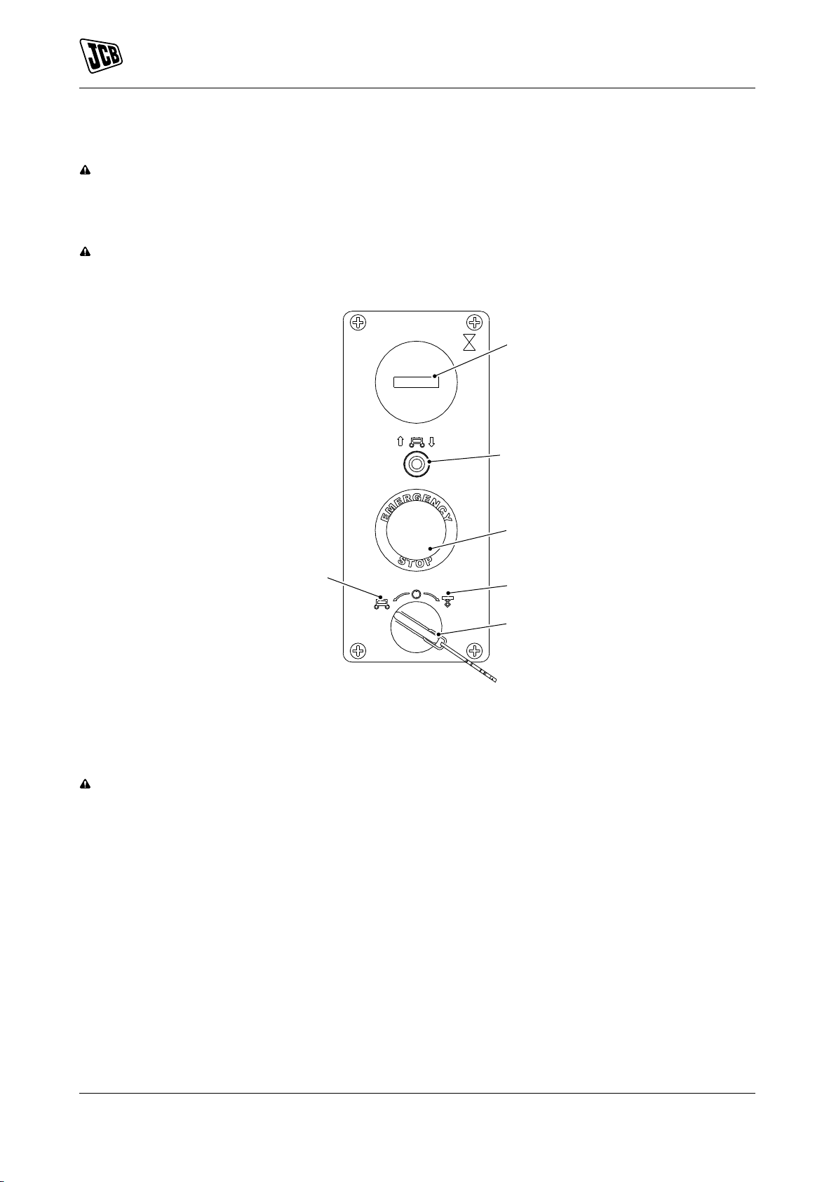
Figure 17.
A Ground control position B Platform control position
C Key switch D Platform raising/lowering toggle switch
E Emergency stop switch F Hourmeter
Platform Controller
WARNING Do not drive the machine with the platform raised except on smooth, firm and level surface free
of obstructions and pot holes.
29 9831/3200-3 29
Page 38

Figure 18.
EMERGENCY
S
T
O
P
A
B
C
D
E
F
G
H
J
K
Operation
Operating Levers/Pedals
A Emergency stop switch B Joystick (forwards/backwards)
C Turn left switch D Turn right switch
E Safety trigger/enable switch F Raise/lower mode
G Drive mode H Display
J Horn button K Speed button
The platform control lever is installed on a portable bracket that can be moved around the platform. The platform
controller can be fitted to the ground controller to suit the operation.
30 9831/3200-3 30
Page 39

Figure 19.
Operation
Operating Levers/Pedals
Platform Controller Display
The display is used to show the battery level and error codes. Refer to: Check (Electrolyte Level)
(Page 77). Refer to Figure 18.
Refer to: Fault-Finding (Page 101).
31 9831/3200-3 31
Page 40

Operation
Working with the Platform
Working with the Platform
General
Trip and Fall Hazards
• Prior to operation, make sure that all operator door and guard rails are fastened and secured in their
proper position.
• It is recommended that all persons in the platform wear full body harnesses with a short lanyard attached
to an authorised lanyard anchor point while operating this machine. For further information refer to JCB
dealer.
• Keep both feet firmly on the platform floor at all times. Never position ladders, boxes, steps, planks or
other similar items on unit to provide additional reach for any purpose.
• Never use the scissor arm assembly to gain accesses to or leave the platform.
• Keep your footwear and the platform floor clean of oil, mud and slippery substances.
Electrocution Hazards
• This machine is not insulated and does not provide protection from contact or proximity to electrical current.
• Maintain distance from electrical lines, apparatus, or any energized (exposed or insulated) parts according
to the Minimum Approach Distance. Refer to Table 4.
• Allow for machine movement and electrical line swaying.
• Maintain a clearance of at least 3m between any part of the machine and its occupants, their tools, and
their equipment from any electrical line or apparatus carrying up to 50,000 volts. One foot additional
clearance is required for every additional 30,000 volts or less.
• The minimum approach distance may be reduced if insulating barriers are installed to prevent contact,
and the barriers are rated for the voltage of the line being guarded. These barriers shall not be part of
(or attached to) the machine. The minimum approach distance shall be reduced to a distance within the
designed working dimensions of the insulating barrier. This determination shall be made by a qualified
person in accordance with the employer, local, or governmental requirements for work practices near
energized equipment.
Table 4. Minimum Approach Distance
Voltage Range Minimum Approach Distance
0 to 300 V Caution!
300V to 50 KV 3m/10ft
50KV to 200KV 5m/15ft
200KV to 350KV 6m/20ft
350KV to 500KV 8m/25ft
500KV to 750KV 11m/35ft
750KV to 1000KV 14m/45ft
Tipping Hazards
• Make sure that the ground conditions are adequate to support the maximum tire load indicated on the tire
load decals located on the chassis adjacent to each wheel. Do not travel on unsupported surfaces.
• The user must be familiar with the driving surface before driving. Do not exceed the allowable sideslope
and grade while driving.
• Do not raise the platform or drive with platform raised while on or near a sloping, uneven, or soft surface.
Make sure that the machine is positioned on the level, solid (slabbed or paved) ground before elevating
platform or driving with the platform in the elevated position.
• Before driving on floors, bridges, trucks, and other surfaces, check allowable capacity of the surfaces.
• Never exceed the maximum work load as specified on the platform. Keep all loads within the confines of
the platform. Evenly distribute the load across the platform, or the machine could become unstable.
• Do not operate the machine when wind conditions exceed the limit.
• Never attempt to use the machine as a crane. Do not tie-off machine to any adjacent structure. Never
attach wire, cable, or any similar item to platform.
• If the platform or scissor pack becomes stuck or snagged on an adjacent or overhead structure, do not
try to free the machine until all personnel are removed from the platform.
• Do not push or pull from the platform against any adjacent or overhead structures.
• Do not cover platform sides or carry large surface area items in the platform when operating outdoors.
The addition of such items increases the exposed wind area of the machine.
32 9831/3200-3 32
Page 41

Operation
A
B
C
D
H
G
F
E
Working with the Platform
• Do not increase platform size with unauthorised deck extensions or attachments.
• Do not raise the platform with the access apertures open. Keep the access apertures closed whilst the
platform is raised.
• If the scissor arm or platform is caught so that one or more wheels are off the ground, all the persons
and tools must be removed before attempting to free the machine. Use a crane, forklift truck, or other
appropriate equipment to stabilise the machine and remove the personnel.
Crushing and Collision Hazards
• Approved head protection must be worn by all operating and ground personnel.
• Keep hand and limbs out of the scissor arm assembly during operation and when raised unless safety
strut installed.
• Watch for obstructions around machine and overhead when driving. Check clearance above, to sides, at
bottom of machine when lifting or lowering the platform.
• Always post a lookout when driving in areas where vision is obstructed.
• Keep non-operating personnel at least 1.8m away from machine during all operations.
• Under all travel conditions, the operator must limit travel speed according to conditions of ground surface,
congestion, visibility, slope, location of personnel, and other factors.
• Be aware of stopping distances in all drive speeds.
• Exercise extreme caution at all times to prevent obstacles from striking or interfering with operating
controls and persons in the platform.
• Ensure that operators of other overhead and floor level machines are aware of the aerial work platform's
presence. Disconnect power to overhead cranes. Barricade floor area if necessary.
• Do not operate over ground personnel. Warn personnel not to work, stand, or walk under a raised platform.
Position barricades on floor as necessary.
Platform Information Decals
The decals are located at the backboard of the platform.
Figure 20.
A Machine model B Indoor rating
C Maximum wind speed D Outdoor rating
E Maximum wind speed F Maximum manual force
G Maximum manual force H Maximum platform height
33 9831/3200-3 33
Page 42

Operation
J
K
L
M
A
B
A
D
C
E
F
H
G
K
J
Working with the Platform
Figure 21.
J Weight distribution on the extended platform K Weight distribution on the extended platform
L Weight distribution on the retracted platform M Weight distribution on the retracted platform
Figure 22.
A Not suitable for outdoor use
The decals are located at the entry point of the platform.
Figure 23.
A Indoor rating (at 0m/s wind speed) B Weight distribution on the extended platform
C Weight distribution on the retracted platform D Outdoor Rating (at 12.5m/s wind speed)
E Weight distribution on the extended platform F Weight distribution on the retracted platform
G Maximum manual force H Wind speed
34 9831/3200-3 34
Page 43

Working with the Platform
A
B
A
J Maximum manual force K Wind speed
Figure 24.
A Not suitable for outdoor use
Extending and Retracting the Platform
WARNING Do not exceed the maximum rated load stated on the platform.
WARNING Do not stand on the extension platform while it is moving or not fixed.
CAUTION Do not lower the platform without completely retracting the platform extension.
Operation
Make sure that platform door is latched correctly before extending or retracting the platform.
There are three fixing positions for the extending platform
1. Press the pedal.
2. Hold and push the extension platform guard rail.
3. Release the pedal when the rail is in one of the three fixing positions. Make sure that it is engaged correctly.
Figure 25.
A Pedal B Fixing positions
4. Press the pedal and pull the extended guardrail to retract the platform.
Folding and Unfolding the Guardrails
CAUTION If the guardrails have been folded down, use extreme caution when entering and leaving the
operator station. Do not operate the controls from the platform when the guard rails are folded.
Fold the guardrails in order as shown. Refer to Figure 26.
1. To fold down each of guardrail, remove the lock pin for that guardrail.
35 9831/3200-3 35
Page 44

Operation
1
2
3
4
5
6
Working with the Platform
2. Take a firm hold on the top of the guardrail, carefully lower it until it is fully folded. Follow the sequence
of folding order
For unfolding the guardrails, follow the reverse sequence of folding order. Make sure that each lock pin is
installed when guardrails are unfolded.
Figure 26.
36 9831/3200-3 36
Page 45

Operation
A
Moving a Disabled Machine
Moving a Disabled Machine
General
Notice: Following any incident, thoroughly inspect the machine. Do not raise the platform until you are sure
that all damage has been repaired and that all controls are operating correctly. Test all functions first from
the ground controller, then from the platform controller.
WARNING Do not use the platform controller to release the platform when it is stuck, snagged or caught.
In this case, use the ground controller only when there are no persons on the platform.
If the machine becomes disabled, the machine must be made safe, lifted onto a transporter and moved to a
location where it can be repaired.
Towing, winching or pushing the machine without following the correct procedure will damage parts of the
hydraulic system. If possible, repair the disabled machine where it stands.
Lower the Platform (Emergency Operation)
The lowering alarm does not sound while lowering but if the machine is switched on the fault alarm will sound
due to lowering without electrical controls. Lowering may continue.
To lower the platform in emergency conditions:
1. Pull out the emergency lowering lever. Refer to Figure 27.
2. Release the lever to stop the operation.
Figure 27.
A Emergency lowering lever
Brake Release Function
1. Put blocks at the front and rear of all four wheels. Make sure they are securely in place.
2. The release valve is at the back of the chassis.
3. Push in the black brake release handle to close the brake valve and trap the brake pressure. Refer to
Figure 28.
4. Firmly pump the red brake release handle as required to release the brake. Refer to Figure 28.
5. Pull the black handle out after the machine is recovered to re-apply the brakes.
37 9831/3200-3 37
Page 46

Moving a Disabled Machine
A
B
Figure 28.
A Black brake release handle B Red brake release handle
Operation
38 9831/3200-3 38
Page 47

Operation
A
Lifting the Machine
Lifting the Machine
General
Lifting by Forklift
Do not lift the machine from the side. Lifting the machine from the side may cause machine damage.
1. Make the machine safe with the platform lowered.
2. Check the extension platform, controller and chassis parts are correctly secured.
3. Remove any loose items from the machine.
4. Keep the machine in the lowered position while lifting with the forklift.
5. Use the forklift slots at the ladder side at the end of the machine.
5.1. Align the forks with the forklift slots at the end of the machine.
5.2. Drive the forklift forwards until the forks carriage almost touches the ladder
5.3. When lifting the machine rotate the forks back slightly to ensure the machine will not slide off the forks.
Travel with the machine at the specified distance from the ground.
Length/Dimension/Distance: 0.4m
5.4. Level the forks before landing the machine.
Figure 29.
A Forklift slots
Lifting by Hoist
1. Make the machine safe with the platform lowered.
2. Check the extension platform, controller and chassis parts are correctly secured.
3. Remove any loose items from the machine.
4. Use the correct length of hoisting rope to prevent damage to the platform base and guardrail.
5. Make sure the hoist rigging is in the correct position. Adjust the hoist rigging to prevent machine damage
and keep the machine in the level position.
39 9831/3200-3 39
Page 48

Figure 30.
X
Y
Operation
Lifting the Machine
X X axis distance Y Y axis distance
5.1. You must consider the location of the centre of gravity on the machine, when you lift the machine.
Refer to Table 5.
Table 5. Location of the Centre of Gravity
Machine Model X axis Y axis
S1530E 620mm 511mm
S1930E 604mm 540mm
S2032E 955mm 625mm
S2632E 956mm 672mm
S2046E 801mm 530mm
S2646E 806mm 570mm
S3246E 808mm 638mm
S4046E 815mm 676mm
S4550E 1,058mm 754mm
40 9831/3200-3 40
Page 49

Operation
Transporting the Machine
Transporting the Machine
General
WARNING The safe transit of the load is the responsibility of the transport contractor and driver. Any
machine, attachments or parts that may move during transit must be adequately secured.
CAUTION Before moving the machine onto the trailer, make sure that the trailer and ramp are free from
oil, grease and ice. Remove oil, grease and ice from the machine tyres. Make sure the machine will not
foul on the ramp angle.
Check the condition of the transport vehicle before the machine is loaded on to its trailer.
Make sure that the transport trailer is suitable for the dimensions and weight of your machine. Refer to: Static
Dimensions (Page 84).
Before transporting the machine make sure you will be obeying the local rules and laws regarding machine
transportation of all the areas that the machine will be carried through.
Loading the Machine onto the Transporting Vehicle/Trailer
Make sure that platform controller is correctly secured. Secure the platform controller to the guardrail at the
mounting position provided in the front right corner of the platform. Insert a bolt through the controller cradle
into the threaded hole provided.
Lifting the Machine onto the Transporting Vehicle/Trailer
1. Turn the machine off and remove the key.
2. Remove any loose items from the machine.
3. Place the blocks at the front and rear of the trailer wheels.
4. Lift the machine on to the trailer.
5. Put blocks at the front and rear of all four wheels. Make sure they are securely in place.
6. Measure the maximum height of the machine from the ground. Make sure the truck driver knows the
clearance height before he drives away.
7. If required remove the lock pins from all four corners of the platform and fold the guardrails.
8. Secure the machine to the trailer bed with suitable chains. Use the tie down points indicated by the safety
decals.
41 9831/3200-3 41
Page 50

Figure 31.
A
Operation
Transporting the Machine
A Lock pin
Driving the Machine onto the Transporting Vehicle/Trailer
1. Put the blocks at the front and rear of the trailer wheels.
2. Lower the ramps and check for suitability.
Refer to: Performance Dimensions (Page 90).
3. Check the condition and security of the trailer side rails to make sure that the machine cannot be driven
off the trailer.
4. Drive the machine onto the trailer and position it taking into account the load distribution.
5. Put blocks at the front and rear of all four wheels. Make sure they are secure in place.
6. Turn the machine off and remove the key.
7. Remove any loose items from the machine.
8. Measure the maximum height of the machine from the ground. Make sure the truck driver knows the
clearance height before he drives away.
9. If required remove the lock pins from all four corners of the platform and fold the guardrails.
10. Secure the machine to the trailer bed with suitable chains. Use the tie down points indicated by the decals.
42 9831/3200-3 42
Page 51

Operation
Operating Environment
Operating Environment
General
For: Lead Acid Battery ............................................................................................................. Page 43
For: Lithium Iron Phosphate Battery ........................................................................................ Page 43
(For: Lead Acid Battery)
In low and high temperature conditions, take the following precautions. They will make it easier to operate and
prevent possible damage to your machine.
The machine has been designed to operate in atmospheric temperatures between -20°C (-4.0°F) and 46°C
(114.7°F). The machine may be used down to -40°C (-39.9°F) with specialist equipment which is available
from your JCB dealer.
(For: Lithium Iron Phosphate Battery)
In low and high temperature conditions, take the following precautions. They will make it easier to operate and
prevent possible damage to your machine.
The machine has been designed to operate in atmospheric temperatures between -20°C (-4.0°F) and 46°C
(114.7°F).
Full rate charging occurs in atmospheric temperatures between 0°C (32.0°F) and 46°C (114.7°F). Slow rate
charging occurs in atmospheric temperatures below 0°C (32.0°F).
43 9831/3200-3 43
Page 52

Notes:
44 9831/3200-3 44
Page 53

Preservation and Storage
Storage
Preservation and Storage
Storage
General
For: Lead Acid Battery ............................................................................................................. Page 45
For: Lithium Iron Phosphate Battery ........................................................................................ Page 45
(For: Lead Acid Battery)
A long period of inactivity can be extremely harmful to lead acid batteries. When placing a battery into storage,
follow the procedure below to ensure that the battery remains healthy and ready for use.
You can store, charge or operate the batteries on a concrete floor.
Avoid locations where freezing temperature are expected. Keeping a battery at a high state of charge will also
prevent freezing. Freezing results in irreparable damage to the battery's plates and container.
Avoid direct exposure to heat sources, such as radiators or heaters. Temperatures above 26.6°C (79.8°F)
accelerate the battery's self discharge characteristics.
Storage Procedure
1. Completely charge the battery before storing.
2. Store the battery in cool, dry location, and protected from the elements.
3. During storage monitor the specific gravity (flooded) or voltage. Batteries in storage should give a boost
charge when they show a 70% charge or less.
4. Completely charge the battery before re-activating.
5. For optimum performance, equalise the batteries (flooded) before putting them back into service.
(For: Lithium Iron Phosphate Battery)
When storing the machine for prolonged periods, keep the batteries installed in the machine.
Storage Procedure
1. Completely charge the battery before storing the machine.
2. Store the machine in a cool, dry location and protect from the elements.
3. If possible, store the machine with AC (Alternating Current) power connected.
4. If not stored connected to AC power, then connect AC power so that the batteries can charge for 48hrs
before use.
Take out of Storage
After long-term storage, it is recommended to service the machine before operation. For more information
contact your JCB dealer.
45 9831/3200-3 45
Page 54

Notes:
46 9831/3200-3 46
Page 55

Maintenance
Introduction
Maintenance
Introduction
General
Your machine has been designed and built to give maximum performance, economy and ease of use under a
wide variety of operating conditions. Prior to delivery, your machine was inspected both at the factory and by
your dealer to make sure that it reaches you in optimum condition. To maintain this condition and trouble free
operation it is important that the routine services, as specified in this manual, are done by an approved JCB
dealer at the recommended specified intervals and it is recommended that this is done by an approved JCB
dealer using genuine JCB parts. Servicing/repairs carried out by unauthorised personnel or the use of nongenuine inferior quality parts could limit machine warranty.
This section of the manual gives full details of the service requirements necessary to maintain your JCB
machine at peak efficiency. A service manual for your machine is available from your JCB dealer. The service
manual contains information on how to repair, disassemble and assemble your machine correctly.
It can be seen from the service schedules on the following pages that many essential service checks must only
be done by a JCB trained specialist competent person. Only JCB dealer service engineers have been trained
by JCB to do such specialist tasks, and only JCB dealer service engineers are equipped with the necessary
special tools and test equipment to do such tasks, thoroughly, safely, accurately and efficiently.
After completing any routine maintenance or repairs you must complete the functional checks according to the
maintenance schedule.
JCB regularly updates its dealers to advise them of any machine developments, changes in specifications and
procedures. Therefore only a JCB dealer is fully able which makes them best placed to maintain and service
your machine.
A service record sheet or book is provided which will enable you to plan your service requirements and keep a
service history record. It must be dated, signed and stamped by your dealer each time your machine is serviced.
Remember, if your machine has been correctly maintained, not only will it give you improved reliability but its
resale value will be greatly enhanced.
When the machine is removed from service, local regulations for machine decommissioning and disposal will
vary. Contact your nearest JCB dealer for further information.
Owner/Operator Support
JCB together with your dealer wants you to be completely satisfied with your new JCB machine. However, if
you do have a problem, you can contact your dealers service department who are there to help you!
You will have been given the names of the relevant service contacts at your dealer when the machine was
supplied.
To get the most from your dealer please help them to satisfy you by providing them with:
1. Your name, address and telephone number.
2. Your machine model and serial number.
3. The date of purchase and hours of work.
4. The nature of the problem.
Remember, only your JCB dealer has access to the vast resources available at JCB to help support you. In
addition, your dealer is able to offer a variety of programmes covering warranty, fixed price servicing, safety
inspections, including weight tests, covering both legal and insurance requirements.
47 9831/3200-3 47
Page 56

Maintenance
Introduction
Service/Maintenance Agreements
To help plan and spread the costs of maintaining your machine, we strongly recommend you take advantage
of the many service and maintenance agreements your dealer can offer. These can be tailor made to meet
your operating conditions, work schedule etc.
Please consult your JCB dealer for details.
Obtaining Spare Parts
If you use non-genuine JCB parts or consumables, then you can compromise the health and safety of the
operator and cause machine failure.
A parts book for your machine is available from your JCB dealer. The parts book will help you identify parts
and order them from your JCB dealer.
Your dealer will need to know the exact model, build and serial number of your machine. Refer to: Product and
Component Identification (Page 9).
The data plate also shows the serial numbers of the engine, transmission and axle(s), where applicable.
Remember, if any of these units have been changed, the serial number on the data plate may be wrong. Check
on the unit itself.
48 9831/3200-3 48
Page 57

Maintenance
Maintenance Safety
Maintenance Safety
General
Raised Machine
Never position yourself or any part of your body inside the raised scissor pack which is not correctly supported.
If the machine moves unexpectedly you could become trapped and suffer serious injury or be killed.
Compressed Air
Compressed air is dangerous. Wear personal protective equipment. Never point a compressed air jet at yourself
or others.
Springs
Always wear personal protective equipment when dismantling assemblies containing components under
pressure from springs. This will protect against eye injury from components accidentally flying out.
Metal Splinters
You can be injured by flying metal splinters when driving metal pins in or out. Use a soft faced hammer or
copper drift to remove and install metal pins. Always wear personal protective equipment.
Repairs
If your machine does not function correctly in any way, get it repaired straight away. Neglect of necessary
repairs could result in an accident or affect your health. Do not try to do repairs or any other type of maintenance
work you do not understand. To avoid injury and/or damage get the work done by a specialist engineer.
Hydraulic Pressure
Hydraulic fluid at system pressure can injure you. Before connecting or removing any hydraulic hose, residual
hydraulic pressure trapped in the service hose line must be vented. Make sure the hose service line has been
vented before connecting or removing hoses. Make sure the machine cannot be started while the hoses are
open.
'O' rings, Seals and Gaskets
Badly installed, damaged or rotted 'O' rings, seals and gaskets can cause leakages and possible accidents.
Renew whenever disturbed unless otherwise instructed. Do not use Triochloroethane or paint thinners near
'O' rings and seals.
Soft Ground
A machine can sink into soft ground. Never work under a machine on soft ground.
Working Under the Machine
Make the machine safe. Make sure the park brake is engaged and machine is fully isolated. Remove the
machine key switch, disconnect the battery. Use blocks to prevent unintentional movement of the wheels.
Hydraulic Hoses
Never re-use hydraulic hose end crimps or use reusable hose end crimps.
Personal Protective Equipment
Use the appropriate personal protective equipment before performing maintenance on the machine, otherwise
you could be injured.
Working at Height
Use appropriate access equipment such as ladders or a working platform if it is necessary to work at height
to perform maintenance tasks on the machine. If you do not use suitable access equipment there is a risk of
falling, resulting in personal injury or death.
Fluids and Lubricants
Fluid Under Pressure
Fine jets of fluid at high pressure can penetrate the skin. Keep face and hands well clear of fluid under pressure
and wear personal protective equipment. Hold a piece of cardboard close to suspected leaks and then examine
the cardboard for signs of fluid. If fluid penetrates your skin, get medical help immediately.
49 9831/3200-3 49
Page 58

Maintenance
Maintenance Safety
Hygiene
JCB lubricants are not a health risk when used correctly for their intended purposes.
However, excessive or prolonged skin contact can remove the natural fats from your skin, causing dryness
and irritation.
Low viscosity oils are more likely to do this, so take special care when handling used oils, which might be
diluted with fuel contamination.
Whenever you are handling oil products you must maintain good standards of care and personal and plant
hygiene. For details of these precautions we advise you to read the relevant publications issued by your local
health authority, plus the following.
Storage
Always keep lubricants out of the reach of children.
Never store lubricants in open or unlabelled containers.
Waste Disposal
CAUTION It is illegal to pollute drains, sewers or the ground. Clean up all spilt fluids and/or lubricants.
Used fluids and/or lubricants, filters and contaminated materials must be disposed of in accordance with
local regulations. Use authorised waste disposal sites.
CAUTION Damaged or spent batteries and any residue from fires or spillage must be put in a closed acid
proof receptacle and must be disposed of in accordance with local environmental waste regulations.
All waste products must be disposed of in accordance with all the relevant regulations.
The collection and disposal of used hydraulic oil must be in accordance with any local regulations. Never pour
used hydraulic oil into sewers, drains or on the ground.
Handling
New Oil
There are no special precautions needed for the handling or use of new oil, beside the normal care and hygiene
practices.
Used Oil
Here are precautions to protect your health when handling used hydraulic oil:
• Avoid prolonged, excessive or repeated skin contact with used oil
• Apply a barrier cream to the skin before handling used oil. Note the following when removing hydraulic
oil from skin:
• Wash your skin thoroughly with soap and water
• Using a nail brush will help
• Use special hand cleansers to help clean dirty hands
• Never use petrol, diesel fuel, or paraffin for washing
• Avoid skin contact with oil soaked clothing
• Don't keep oily rags in pockets
• Wash dirty clothing before re-use
• Throw away oil-soaked shoes
50 9831/3200-3 50
Page 59

Maintenance
Maintenance Safety
First Aid - Oil
Eyes
In the case of eye contact, flush with water for 15min. If irritation persists, get medical attention.
Swallowing
If oil is swallowed do not induce vomiting. Get medical advice.
Skin
In the case of excessive skin contact, wash with soap and water.
Spillage
Absorb with sand or a locally approved brand of absorbent granules. Scrape up and remove to a chemical
disposal area.
Fires
WARNING Do not use water to put out an oil fire. This will only spread it because oil floats on water.
Extinguish oil and lubricant fires with carbon dioxide, dry chemical or foam.
Batteries
For: Lead Acid Battery ............................................................................................................. Page 51
For: Lithium Iron Phosphate Battery ........................................................................................ Page 53
(For: Lead Acid Battery)
Warning Symbols
DANGER Set all switches to off before disconnecting and connecting the battery. When disconnecting the
battery, take off the earth (-) lead first.
When reconnecting, attach the positive (+) lead first.
DANGER Batteries give off explosive gases. Keep flames and sparks away from the battery. Do not smoke
close to the battery. Make sure there is good ventilation in closed areas where batteries are being used
or charged. Do not check the battery charge by shorting the terminals with metal. Use a hydrometer or
voltmeter.
WARNING Do not connect the charger when the batteries are not connected. Doing so could result in
danger of live terminals from the charger.
Do not carry out maintenance on a machine whilst the charger is connected to an external power supply
(i.e. do not work on a live machine). Cables from the charger to the batteries may remain live even if the
batteries are disconnected/removed from the machine. There is a risk of serious electrical shock.
Always disconnect all external power supplies to the machine before carrying out maintenance.
WARNING Battery electrolyte is toxic and corrosive. Do not breathe the gases given off by the battery. Keep
the electrolyte away from your clothes, skin, mouth and eyes. Wear safety glasses.
CAUTION Understand the electrical circuit before connecting or disconnecting an electrical component. A
wrong connection can cause injury and/or damage.
CAUTION Damaged or spent batteries and any residue from fires or spillage must be put in a closed acid
proof receptacle and must be disposed of in accordance with local environmental waste regulations.
The following warning symbols may be found on the battery.
51 9831/3200-3 51
Page 60

Figure 32.
A
B C
D E F
A Keep away from children B Shield eyes
C No smoking, no naked flames, no sparks D Explosive gas
E Battery acid F Note operating instructions
Maintenance
Maintenance Safety
52 9831/3200-3 52
Page 61

Maintenance
Maintenance Safety
First Aid - Electrolyte
Eyes
In the case of eye contact, flush with water for 15min. always get medical attention.
Swallowing
Do not induce vomiting. Drink large quantities of water or milk. Then drink milk of magnesia, beaten egg or
vegetable oil. Get medical help.
Skin
Flush with water, remove affected clothing. Cover burns with a sterile dressing then get medical help.
(For: Lithium Iron Phosphate Battery)
General Rules
DANGER Set all switches to off before disconnecting and connecting the battery. When disconnecting the
battery, take off the earth (-) lead first.
When reconnecting, attach the positive (+) lead first.
WARNING Do not connect the charger when the batteries are not connected. Doing so could result in
danger of live terminals from the charger.
Do not carry out maintenance on a machine whilst the charger is connected to an external power supply
(i.e. do not work on a live machine). Cables from the charger to the batteries may remain live even if the
batteries are disconnected/removed from the machine. There is a risk of serious electrical shock.
Always disconnect all external power supplies to the machine before carrying out maintenance.
CAUTION Understand the electrical circuit before connecting or disconnecting an electrical component. A
wrong connection can cause injury and/or damage.
Work on the Li-ion Battery should be carried out by qualified personnel only.
While working on the Li-ion Battery wear protective glasses and clothing.
Any uncovered battery material such as electrolyte or powder on the skin or in the eyes must be flushed with
plenty of clean water immediately. Then seek medical assistance. Spillages on clothing should be rinsed out
with water.
Terminals of the Li-ion Battery are always a live; therefore do not place items or tools on the Li-ion Battery.
Avoid short circuits, too deep discharges and too high charge currents. Do not wear any metallic items such
as watches, bracelets etc. In case of fire, you must use a type D, foam or CO2 fire extinguisher.
Never try to open or dismantle the Li-ion Battery. Electrolyte is very corrosive. In normal working conditions
contact with the electrolyte is impossible. If the battery casing is damaged do not touch the exposed electrolyte
or powder because it is corrosive.
Too deep discharges damage the Li-ion battery seriously and can even be dangerous. Therefore, JCB fit a
safety relay within the system. Do not tamper or modify the existing system. If charged after the Li-ion battery
was discharged below the Discharge cut-off voltage, or when the Li-ion battery is damaged or overcharged, the
Li-ion battery can release a harmful mixture of gasses such as phosphate. Make sure there is good ventilation
in closed areas where batteries are being used or charged.
It is recommended not to remove the LI-ion batteries from the machine. However if this is necessary, observe
the following safety warnings: Li-ion Batteries are heavy. If involved in an accident they can become a projectile.
Ensure adequate and secure mounting and always use suitable handling equipment for transportation. Handle
with care because Li-ion Batteries are sensitive to mechanical shock.
53 9831/3200-3 53
Page 62

Maintenance
Maintenance Safety
Transportation
The Li-ion battery must be transported in its original or equivalent package and in an upright position. If the
battery is in its package, use soft slings to avoid damage. Do not stand below a Li-ion battery when it is hoisted.
Never lift the battery at the terminals, only lift the battery at the handles.
Batteries are tested according to UN Handbook of Tests and Criteria, part III, sub section 38.3 (ST/SG/AC.10/11/
Rev.5). For transport the batteries belong to the category UN3480, Class 9, Packaging Group II and have to be
transported according to this regulation. This means that for land and sea transport (ADR, RID & IMDG) they
have to be packed according to packaging instruction P903 and for air transport (IATA) according to packaging
instruction P965. The original packaging satisfies these instructions.
Disposal
Batteries marked with the recycling symbol must be processed via a recognized recycling agency. By
agreement, they may be returned to the manufacturer. Batteries must not be mixed with domestic or industrial
waste.
First Aid - Electrolyte
Eyes
In the case of eye contact, flush with water for 15min. always get medical attention.
Swallowing
Do not induce vomiting. Drink large quantities of water or milk. Then drink milk of magnesia, beaten egg or
vegetable oil. Get medical help.
Skin
Flush with water, remove affected clothing. Cover burns with a sterile dressing then get medical help.
54 9831/3200-3 54
Page 63

Maintenance
Maintenance Schedules
Maintenance Schedules
General
WARNING Maintenance must be done only by suitably qualified and competent persons.
Before doing any maintenance make sure the machine is safe, it must be correctly parked on solid, level
ground.
To prevent anyone starting the machine, remove the key. Disconnect the battery when you are not using
electrical power. If you do not take these precautions you could be killed or injured.
A badly maintained machine is a danger to the operator and the people working around the operator. Make
sure that the regular maintenance and lubrication tasks listed in the service schedules are done to keep the
machine in a safe and efficient working condition.
Apart from the daily tasks, the schedules are based on time. Keep a regular check on the hourmeter readings
to monitor the hourmeter equivalents. When there is no hourmeter installed, use the calendar equivalents to
determine the service intervals.
Do not use a machine which is due for a service. Make sure any defects found during the regular maintenance
checks are corrected immediately.
How to Use the Maintenance Schedules
The schedules show the service tasks which must be done and their intervals.
The services must be done at either the hourly interval or the calendar equivalent, whichever occurs first.
The intervals given in the schedules must not be exceeded. If the machine is operated under severe conditions
(high temperature, dust, water, etc.) shorten the intervals. Where local regulations require more frequent
checks, the local regulations intervals should be followed.
Table 6.
Service task can be completed by a competent operator. Details of how to complete the service task are given in the Operator's Manual.
We recommend that a Service Engineer completes the service task. Details of
how to complete the service task are given in the Service Manual.
Maintenance Intervals
Table 7.
Interval (h) Calendar Equivalent
10 Daily
50 Weekly
100 Monthly
250 Three months
500 Six months
1000 Yearly
1500 Eighteen months
2000 Two years
55 9831/3200-3 55
Page 64

Pre-start Cold Checks, Service Points and Fluid Levels
Table 8.
Component Task Daily Weekly Month-ly3
Months6Months
Operator's Manu-alCheck
(condition)
Safety Labels Check
(condition)
Hydraulic hoses Check
(condition)
Hydraulic oil Check (lev-
el)
Hydraulic oil Check
(leaks)
Hydraulic oil Replace
Maintenance
Maintenance Schedules
Yearly 18
Months
2 Years
Hydraulic return
filter
Vent filter - hydraulic tank
Battery electrolyte
(lead acid batteries)
Battery electrolyte
(lead acid batteries)
Electric wire Check
Welds Check
Machine damage,
missing parts
Fasteners Check
Lateral guard rail Check
Chassis sliders Check
Wheel rim and
tyre
Lift ram(s) Grease
Replace
Replace
Check (level)
Check
(leaks)
(condition)
(condition)
Check
(condition)
(condition)
(condition)
(condition)
Check
(condition)
Steer pivots Grease
Scissor base slid-erGrease
Scissor basket
slider
Wheel nut split
pin
Tilt sensor Check
Pothole protection system
56 9831/3200-3 56
Grease
Check
(condition)
(condition)
Check
(condition)
Page 65

Functional Tests and Final Inspection
Table 9.
Component Task Daily Weekly Month-ly3
Ground controller
Emergency stop Check (op-
eration)
Platform raise
and lower functions
Platform emergency lowering
Ignition switch Check (op-
Platform controller
Emergency stop Check (op-
Platform raise
and lower functions
Horn Check (op-
Steering Check (op-
Drive and brake Check (op-
General
Limited driving
speed (with platform lifted and
stowed)
Tilt sensor Check (op-
Pothole protection system
Ventilation system- hydraulic
tank
Overload System Check (op-
Hydraulic system
pressure
Hydraulic system
functional test
Overload test Check (op-
RCBO (Residual current Circuit Breaker with
Over current protection)
Check (operation)
Check (operation)
eration)
eration)
Check (op-
eration)
eration)
eration)
eration)
Check (operation)
eration)
Check (op-
eration)
Check (op-
eration)
eration)
Check (set-
tings)
Check (op-
eration)
eration)
Check (op-
eration)
Months6Months
Maintenance
Maintenance Schedules
Yearly 18
Months
2 Years
57 9831/3200-3 57
Page 66

Maintenance
Maintenance Positions
Maintenance Positions
General
Make the machine safe before you start a maintenance procedure.
1. Park the machine on level, solid (slabbed/paved) ground.
2. Remove the machine key switch.
3. Disconnect the battery to prevent accidental operation.
4. Put the chocks on the side of all wheels.
Maintenance Position- Platform Raised
WARNING If a second person is involved with the operation ensure that the machine controls are not
operated whilst they are in the working envelope of the machine and attachment, otherwise the other person
could be killed or injured if a control is moved accidentally.
Make sure that the safety strut is installed before performing the maintenance task on raised platform.
When installing the upper safety strut always maintain three points of contact with ladder and scissor end bar.
Use scissor end bar as handrails.
58 9831/3200-3 58
Page 67

Figure 33.
A
B
Maintenance
Maintenance Positions
A Upper safety strut B Lower safety strut
The minimum clearance height required to install the safety struts is shown. Refer to Table 10.
Table 10.
Machine Length
S1530E 3.25m
S1930E 3.61m
S2032E 3.3m
S2046E 3.3m
S2632E 3.75m
S2646E 3.75m
S3246E 4.2m
S4046E 4.6m
S4550E 4.6m
59 9831/3200-3 59
Page 68

Maintenance Position- Platform Lowered
B
Make sure that the safety strut is in stored position before lowering the platform.
Figure 34.
Maintenance
Maintenance Positions
B Safety struts stowage position
60 9831/3200-3 60
Page 69

General
B
A
E
D
C
F
G
Hydraulic Compartment
Maintenance
Service Points
Service Points
Figure 35.
A Main control relay B Hydraulic oil level indicator sight hole
C Hydraulic oil filler cap D Hydraulic oil filter
E Platform control connection F Hydraulic breather
G Secondary fuses
61 9831/3200-3 61
Page 70

Battery Compartment
B
C
A
E
G
D
F
E
GD
F
A
B
C
Maintenance
Service Points
Figure 36. Lead Acid Battery
A Battery isolator B Primary fuses (275A rating)
C Battery Charger D Primary fuse (20A rating)
E DC contactor resistor F Battery charger status sight hole
G DC contactor
Figure 37. Lithium Iron Phosphate Battery
A Battery isolator B Primary fuses (275A rating)
C Battery Charger D Primary fuse (20A rating)
E DC contactor resistor F Battery charger status sight hole
G DC contactor
62 9831/3200-3 62
Page 71

Maintenance
C
A
B
Access Apertures
Access Apertures
General
WARNING The hydraulic and battery components will be hot after the unit has been running. Allow the
components to cool before servicing the unit otherwise you could be burned.
When moved to their maintenance position, the access panels give access to parts or areas of the machine
that are not required during machine operation.
Before you operate the machine, make sure that all of the access panels are correctly in their closed or installed
positions.
Battery Cover
Open
1. Make the machine safe.
2. Remove the key from the machine.
3. Use the key to unlock the cover.
4. Press the lock and pull the handle to open the cover. Refer to Figure 38.
Figure 38.
A Lock B Handle
C Cover
Close
1. Close the cover.
2. Make sure the cover is closed correctly.
3. Use the key to lock the cover. Refer to Figure 38.
Hydraulic Compartment Cover
Open
1. Make the machine safe.
2. Remove the key from the machine.
3. Use the key to unlock the cover.
4. Press the lock and pull the handle to open the cover.
63 9831/3200-3 63
Page 72

Figure 39.
A
B
C
A Lock B Handle
C Cover
Close
1. Close the cover.
2. Make sure the cover is secured correctly.
3. Use the key to lock the cover.
Maintenance
Access Apertures
64 9831/3200-3 64
Page 73

Maintenance
Body and Framework
Body and Framework
General
Check (Condition)
1. Make sure that all of the guards and protective devices are in position, secured by their locking devices
and free from damage.
2. Inspect all of the steelwork for damage. Include the following:
2.1. Examine all of the pivot point welds.
2.2. Examine the condition of all the pivot pins.
2.3. Check that the pivot pins are correctly in position and secured by their locking devices.
3. Check the steps and guardrails are undamaged and correctly attached.
4. Check that all of the safety and instructional labels are undamaged and in position. Install new labels where
necessary.
5. Note any damaged paintwork for future repair.
6. Inspect the machine for broken or loose fasteners.
7. Raise the platform until pot hole protection is activated. Check the condition of the pot hole protection bars.
65 9831/3200-3 65
Page 74

Maintenance
A
B
Safety Equipment
Safety Equipment
Check (Operation)
If any of the safety equipment is defective stop using the machine until the defect has been rectified.
Pot Hole Protection System
Pot hole protection system should be activated when the platform raised. The pot hole protection system is
monitored by two limit switches to ensure correct deployment. If the pothole protection system does not activate
the alarm will sound and the platform will not raise any higher.
1. Raise the platform.
2. Install the safety strut.
3. The pot hole protection plates should automatically unfold.
4. Inspect the pothole protection plates on both sides of the chassis. The plates should be lowered fully to
the vertical position.
5. Inspect the linkages inside the compartments on both sides of the chassis. The linkages should be
connected, with no visible signs of damage.
6. Remove the safety strut.
7. Lower the platform.
8. The pot hole protection plates should automatically fold.
9. Place an obstacle under the plate on each side.
10. Raise the platform. The platform should automatically stop when the plate cannot be deployed. Check the
reaction: the alarm should sound at the platform controller and the chassis, the lights should flash on the
chassis, the LCD (Liquid Crystal Display) displays should show "18".
Figure 40.
A Pot hole protection plate - unfold position B Pot hole protection plate - fold position
Tilt Sensor
1. Raise the platform.
2. Install the safety strut.
3. Use a pole/device to push the tilt sensor down on one side until the sensor is tilted at its highest angle.
Hold the tilt sensor down at least for at least 1.5 seconds. Check the reaction: the alarm should sound
at the platform controller and the chassis, the lights should flash on the chassis, the LCD displays should
show "LL".
66 9831/3200-3 66
Page 75

A
A Tilt sensor
Maintenance
Safety Equipment
Figure 41.
67 9831/3200-3 67
Page 76

Maintenance
Brakes
Brakes
Park Brake
Check (Operation)
The brakes must be able to hold the machine on any slope it is able to climb. Refer to: Driving on Slopes
(Page 26).
Make a note of the following.
• You must check the brakes for correct operation at regular intervals.
• The correct brake function is necessary for safe machine operation.
• The brake function must operate smoothly, free of hesitation, jerking and unusual noise.
• Do this procedure with the machine on a firm, level surface that is free of obstructions.
1. Make the machine safe with the platform lowered.
2. Make sure that the platform extension is in the fully retracted position.
3. Put a mark on the ground to use as a test line.
4. Turn the ignition switch to platform control.
5. Pull out the ground emergency stop button to the ON position.
6. Pull out the platform emergency stop button to the ON position.
7. Make a note of the point on the machine (contact patch of a tyre) as a visual reference when you cross
the test line.
8. Press the drive function button (if installed).
9. Press and hold the drive/steer function enable switch on the control handle.
10. Move the control lever in the forward direction.
11. Bring the machine to top drive speed before you reach the test line.
12. Release the control lever when the selected reference point on the machine crosses the test line.
13. Measure the distance between the test line and the machine reference point.
14. Make sure that the braking distance is within the specified limits.
15. Raise the platform.
16. Do the steps 3 to 13 with the platform raised.
17. Make sure that the braking distance is within the specified limits.
68 9831/3200-3 68
Page 77

Steering System
General
Check (Operation)
1. Enable the joystick by pressing the safety trigger/enable switch.
Refer to: Operating Levers/Pedals (Page 29).
2. Press the joystick (forward/back).
3. Press the left steering switch to turn left.
4. Press the right steering switch to turn right.
Maintenance
Steering System
69 9831/3200-3 69
Page 78

Maintenance
Tyres
Tyres
General
Check (Condition)
Always drive with consideration for the condition of the tyres. Check the tyres daily for the signs of damage
and wear. For example:
• Signs of distortion
• Cuts
• Embedded objects (nails, etc.)
• Continuous tread
• Edge damage
• Uneven wear
70 9831/3200-3 70
Page 79

Maintenance
Hydraulic System
Hydraulic System
General
Check (Condition)
Hydraulic Hoses
WARNING Damaged hoses can cause fatal accidents. Examine the hoses regularly. Do not use the machine
if a hose or hose fixture is damaged.
WARNING Fine jets of fluid at high pressure can penetrate the skin. Keep face and hands well clear of
pressurised fluid and wear protective glasses. If fluid penetrates your skin, get medical help immediately.
Examine the hoses for:
Damaged hose ends
Worn outer covers
Ballooned outer covers
Kinked or crushed hoses
Exposed armouring in the outer covers
Displaced hose end fittings.
Worn cover sheathing or hose burst protection covering.
Replace a damaged hose before you use the machine again.
The replacement hoses must be of the same size, standard and pressure rating. If necessary, for more
information contact your JCB dealer.
Connecting the Hydraulic Hoses
1. Make the machine safe.
Refer to: Maintenance Positions (Page 58).
2. Vent the hydraulic system.
3. Check the hoses and adaptors for damage.
4. Connect the hoses:
4.1. Make sure that the hose is not twisted. Pressure applied to a twisted hose can cause the hose to fail
or the connections to loosen.
Figure 42.
4.2. Make sure that the hose does not touch hot parts. High ambient temperatures can cause the hose
to fail.
4.3. Make sure that the hose does not touch parts which can rub or cause abrasion.
71 9831/3200-3 71
Page 80

Maintenance
Hydraulic System
4.4. Use the hose clamps (where possible) to support long hose runs and keep the hoses away from
moving parts, etc.
Figure 43.
4.5. To allow for length changes when the hose is pressurised, do not clamp at the bend. The curve absorbs
the change.
Figure 44.
5. Check for leaks:
5.1. Start the machine.
5.2. Operate the related controls to increase the pressure in the hydraulic system.
5.3. Stop the machine then remove the key.
5.4. Check for indications of leakage at the hose connections. Correct, as necessary.
Disconnecting the Hydraulic Hoses
1. Make the machine safe.
Refer to: Maintenance Positions (Page 58).
2. Vent the hydraulic system.
3. Disconnect the hoses.
4. Check the hoses and adaptors for damage.
5. If necessary, install the blanking caps.
6. Check for leaks:
6.1. Start the machine.
6.2. Operate the related controls to increase the pressure in the hydraulic system.
6.3. Stop the machine then remove the key.
6.4. Check for indications of leakage at the hose connections. Correct, as necessary.
72 9831/3200-3 72
Page 81

Maintenance
A B
Hydraulic System
Quick Release Couplings
WARNING The external surfaces of the couplings must be clean before connecting or disconnecting.
Ingress of dirt will cause fluid leaks and difficulty in connecting or disconnecting. You could be killed or
seriously injured by faulty quick release couplings.
The flat face quick release couplings allow the operator to remove and install attachments swiftly and efficiently.
Generally, your machine pipework will be installed with a female coupling and a male coupling. The optional
attachment hoses will also be installed with a female coupling and a male coupling.
Figure 45.
A Female coupling B Male coupling
The quick release couplings will be trouble free and relatively easy to connect and disconnect, if they are kept
clean and used correctly. The recommendations listed below must always apply when using flat face quick
release couplings.
Read the correct connecting and releasing procedures before you install or remove any optional attachment
connected with quick release couplings.
Essential do's:
• Before connecting or removing any hydraulic hose, the residual hydraulic pressure trapped in the service
hose line must be vented. Make sure the hose service line has been vented before connecting or removing
the hoses.
• Always wipe the two mating faces clean before connecting.
• Use caps and plugs when the couplings are disconnected.
• Always align the external locking ball (if used) with the notch in the locking sleeve and then pull the locking
sleeve back fully to disconnect.
• If a coupling sticks, first check that pressure has been released. Make sure the locking ball and notch
in the locking sleeve are aligned, pull back the sleeve and twist the couplings apart. Sticking is normally
caused by dirt in the coupling or physical damage due to abuse.
• Connect and disconnect the new couplings two or three times to work the PTFE seals. Sometimes a new
coupling will stick if the seal has not been worked.
• When connecting the couplings, only apply the spanner or grips to the hexagon and nowhere else.
• Avoid damage to the coupling faces. Burrs and scratches cause damage to the seals and cause leaks.
They can also impede connection and disconnection of the couplings.
• Periodically lubricate the internal locking balls on the female half of the coupling with silicone grease.
Essential don'ts:
• Never try to reconnect using a damaged half coupling as this will destroy the seals in the mating half and
necessitate replacement of both halves.
• Do not leave the coupling where it may be run over by a machine or otherwise crushed, this will distort
the sleeve and prevent connection and disconnection.
• Never try to turn the sleeve when the coupling is disconnected as this will cause the locking ball to jam
under the locking sleeve and damage the coupling.
• Never try to strip the coupling down, there are no user serviceable parts. If the coupling is damaged it
must be replaced with a new one.
• Never hit the centre poppet of the coupling to try and release the locked in pressure. This can cause
irreparable damage to the coupling and serious injury.
• When connecting the couplings, never clamp on the sleeve of the female or nose of the male, this will
cause distortion and/or damage.
• Never subject the couplings to external forces, especially side load. This can decrease the life of the
coupling or cause failure.
73 9831/3200-3 73
Page 82

Maintenance
C E
D
Hydraulic System
• Never allow the torsional forces transmitted from the hoses to unscrew/screw together the couplings.
• Never use a coupling as a plug.
• Do not connect and disconnect with pressure in the line unless the coupling type is specifically designed
to do so.
Connecting Quick Release Couplings
1. Remove any residual hydraulic pressure trapped in the service line hose.
2. Wipe the two faces of the male and female couplings and make sure they are clean.
3. Make sure that ball in the female coupling is located in one of its slots.
4. Connect the male coupling into the female coupling.
5. Where applicable, rotate the sleeve half a turn and make sure that the locking ball does not align with
the slot.
Figure 46.
C Ball D Slot
E Sleeve
Disconnecting Quick Release Couplings
1. Remove any residual hydraulic pressure trapped in the service line hose.
2. Where applicable, align the slot with ball.
3. Pull back the sleeve to release the coupling.
Oil
Check (Level)
1. Make the machine safe with the platform lowered.
Refer to: Maintenance Positions (Page 58).
2. Look at the hydraulic fluid in the sight hole. If the hydraulic fluid is cloudy, water or air is the system. Water or
air is in the system can damage the hydraulic pump. Contact your JCB dealer if the hydraulic fluid is cloudy.
Refer to: Service Points (Page 61).
3. If necessary, add the recommended hydraulic fluid.
3.1. Open the hydraulic filler cap.
3.2. Use a suitable container to add the hydraulic fluid through the filler port.
3.3. Check the level of hydraulic fluid.
3.4. Close the filler cap.
74 9831/3200-3 74
Page 83

Maintenance
Electrical System
Electrical System
General
Check (Operation)
Make sure all of the electrical equipment operates correctly, for example:
• Switches
• Warning lights
• Beacon
• Alarms
• Horn
• Hourmeter/display
• Battery
• Lights
All defective equipment must be repaired before the machine is used.
Check (Condition)
For: Lead Acid Battery ............................................................................................................. Page 75
(For: Lead Acid Battery)
WARNING Battery electrolyte is toxic and corrosive. Do not breathe the gases given off by the battery. Keep
the electrolyte away from your clothes, skin, mouth and eyes. Wear safety glasses.
DANGER Batteries give off explosive gases. Keep flames and sparks away from the battery. Do not smoke
close to the battery. Make sure there is good ventilation in closed areas where batteries are being used
or charged. Do not check the battery charge by shorting the terminals with metal. Use a hydrometer or
voltmeter.
CAUTION Understand the electrical circuit before connecting or disconnecting an electrical component. A
wrong connection can cause injury and/or damage.
Examine the electrical circuits regularly for:
• Damaged connectors
• Loose connections
• Chafing on the wiring harnesses
• Corrosion
• Missing insulation
• Incorrect routing of the wiring harnesses
• Insulation covers on battery terminals and leads
Do not use the machine if one or more of these faults are found. You must make sure that the electrical circuit
is repaired immediately.
Battery
Clean
For: Lead Acid Battery ............................................................................................................. Page 75
(For: Lead Acid Battery)
WARNING Keep metal watch straps and any metal fasteners on your clothes, clear of the positive (+)
battery terminal. Such items can short between the terminal and nearby metal work. If it happens you can
get burned.
1. Make the machine safe.
Refer to: Maintenance Positions (Page 58).
75 9831/3200-3 75
Page 84

Maintenance
Electrical System
2. Get access to the battery.
Refer to: Access Apertures (Page 63).
3. If the terminal posts are corroded and covered with white powder wash them with hot water. If there is
considerable corrosion, clean the terminal posts with a wire brush or abrasive paper. Refer to Figure 47.
Figure 47.
4. Apply a thin layer of petroleum jelly to the terminal posts.
Connect
CAUTION The machine is negatively earthed. Always connect the negative pole of the battery to earth.
When connecting the battery, connect the earth (-) lead last.
When disconnecting the battery, disconnect the earth (-) lead first.
1. Get access to the batteries.
Refer to: Disconnect (Page 76).
2. Make sure that the terminal covers are fitted except exposed terminal posts.
3. Connect the battery leads. Connect the earth (-) terminal last.
4. If the machine has a battery isolator key, then connect the isolator.
Refer to: Battery Isolator (Page 22).
Disconnect
WARNING Do not use batteries lighter than the original ones. The batteries work as counterweight and are
critical to the stability of machine.
WARNING Do not use the machine with the counterweights removed. The counterweights are critical to
the stability of machine.
CAUTION Batteries are heavy. Use an appropriate number of people to lift the batteries. Use appropriate
lifting techniques.
CAUTION The machine is negatively earthed. Always connect the negative pole of the battery to earth.
When connecting the battery, connect the earth (-) lead last.
When disconnecting the battery, disconnect the earth (-) lead first.
Notice: Do not isolate the machine electrics when the machine is in operation, this may cause damage
to the machine electrics.
1. Make the machine safe.
Refer to: Maintenance Positions (Page 58).
2. Get access to the batteries.
76 9831/3200-3 76
Page 85

Maintenance
A
Electrical System
Refer to: Access Apertures (Page 63).
3. If the machine has a battery isolator, then disconnect the battery isolator.
Refer to: Battery Isolator (Page 22).
4. Disconnect the battery leads. Disconnect the earth (-) terminal first.
Check (Electrolyte Level)
For: Lead Acid Battery ............................................................................................................. Page 77
(For: Lead Acid Battery)
WARNING Do not top the battery up with acid. The electrolyte could boil out and burn you.
1. Make the machine safe.
2. Open the battery compartment cover.
3. Remove the vent caps.
4. Check the electrolyte level.
4.1. The minimum level is at the top of the plates.
4.2. If necessary, add just enough distilled water to cover the plates at this time.
5. Install the vent caps.
6. Put batteries on a complete charge before adding any additional distilled water.
7. Remove the vent caps.
8. Add distilled water until the electrolyte level is below the bottom of the fill well by the specified value.
Distance: 3.175mm
8.1. If necessary, use a piece of rubber as a dipstick to determine this level.
Figure 48.
A Electrolyte level (3.175mm)
9. Clean the vent caps.
10. Install the vent caps.
Check (Charge Level)
WARNING Do not connect the charger when the batteries are not connected. Doing so could result in
danger of live terminals from the charger.
Do not carry out maintenance on a machine whilst the charger is connected to an external power supply
(i.e. do not work on a live machine). Cables from the charger to the batteries may remain live even if the
batteries are disconnected/removed from the machine. There is a risk of serious electrical shock.
77 9831/3200-3 77
Page 86
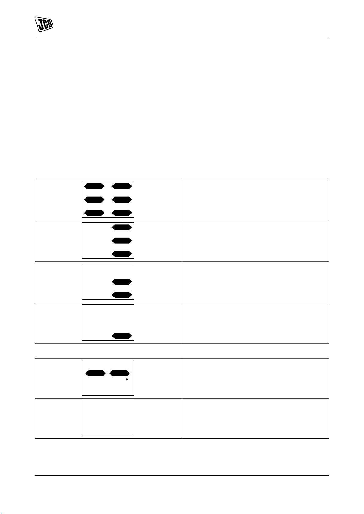
Maintenance
Electrical System
Always disconnect all external power supplies to the machine before carrying out maintenance.
The battery should be checked when the motor is running, this will avoid mis-reading the charge level because
of battery voltage recovery due to lack of current draw.
An approximate charge level of the battery is shown on the platform controller and battery charger display.
When the level of batteries is about 20%, the battery must be charged. Never let the battery fully discharge
before charging.
When the battery voltage is low, select low speed mode and drive at low speed / half throttle to a charge location.
For machines with Lithium Iron Phosphate Batteries; If the machine is driven on low battery level for too long,
the battery management system will cut off the electrical supply from the batteries, to protect the batteries from
too deep a discharge. Restarting the machine will have no effect. The machine will be non-operational until the
charger is connected to an external power supply.
Table 11. Platform Control Display
Fully charged
30%
Charge battery now
Battery too low - charge battery now
Table 12. Ground Control Display
Operational
Not operational
Charge the Battery
When charging the batteries, refer to the battery charger display to view the charge status of the batteries.
Refer to Figure 49.
78 9831/3200-3 78
Page 87

Figure 49.
Blink
10+ 20+ 30+
Charger Status
USB
Status
D
A
B
C
A
Maintenance
Electrical System
A 50% B 70%
C 100% D USB (Universal Serial Bus) status
Only use the original charger installed to the machine with the original batteries. Charge the battery in a well
ventilated place. Use an appropriate grounded industrial power supply with the correct AC (Alternating Current)
input voltage to charge.
1. Make sure the battery is properly connected before charging. Check the terminal connections are tight.
2. Remove the ventilation cap and check the electrolyte level is above the polar plate. Replenish with distilled
water if required. Do not overfill. Install the ventilation cap.
3. Connect the charger to the AC supply. Refer to Figure 50.
Figure 50.
A Battery charging socket
Battery and power to platform connectors may be mounted rigidly in the mounting holes or hung loose with
their cables according to operator preference.
Fault Indicator
When a fault occurs, all three battery charge indicator LED (Light Emitting Diode)'s will blink at the same time.
Refer to Table 13.
79 9831/3200-3 79
Page 88

Maintenance
Electrical System
Table 13.
Blinking Frequency
1 The battery is not connected or the battery
2 Abnormal AC Power Input (Voltage) Check AC input cord is connected between charger
3 Charger High Temperature Protection Charger shuts down and goes into protection mode
4 Battery High Temperature Protection Charger will reduce or even stop charging when the
5 Output Current is too large Contact JCB dealer for repair.
6 Battery Voltage is too high (>28.5V) Check and make sure that the correct output battery
7 Battery Voltage is too low (<17.5V) Check and make sure that the correct output bat-
Cause Remedy
No charging at the time or the battery voltage is less
voltage is too low
than 4V.
and AC outlet. Make sure AC plug is tightly secured
into the AC outlet.
due to charger / environmental temperature too high
for charger to function properly. Place the charger into an area with ambient air flow or to a cooler place.
Disconnect the charger and wait for 15–20min before
reconnecting it for charging.
battery temperature exceeds 50°C (121.9°F). This is
to protect the battery from overheating. Disconnect
the charger and wait for 15–20min before reconnecting it for charging.
voltage is connected.
tery voltage is connected. (The charger keeps charging normally even though the battery voltage is more
than 4V.)
Battery Isolator
Check (Operation)
Notice: Do not isolate the machine electrics when the machine is in operation, this may cause damage
to the machine electrics.
1. Isolate the machine electrics.
2. Make sure that the machine electrics are isolated.
A defective isolator must be repaired before the machine is used. For more information, contact your JCB
dealer.
Fuses
Replace
The electrical circuits are protected by fuses. If a fuse blows, find out why before a new one is installed.
Primary Fuses
The primary fuses are located in the battery compartment compartment. Refer to: General (Page 61).
Secondary Fuses
The secondary fuses are located in the hydraulic compartment compartment. Refer to: General (Page 61).
80 9831/3200-3 80
Page 89

Relays
Replace
The relays are situated in the hydraulic compartment. Refer to: General (Page 61).
Maintenance
Electrical System
81 9831/3200-3 81
Page 90

Notes:
82 9831/3200-3 82
Page 91

Technical Data
Introduction
Technical Data
Introduction
General
All the rated operating capacities/rated lift capacities are based on the criteria of the machine being level on a
firm supporting ground and wind speed is below the specified limit.
83 9831/3200-3 83
Page 92

Technical Data
Static Dimensions
Static Dimensions
Dimensions
For: S1530E ............................................................................................................................. Page 84
For: S1930E ............................................................................................................................. Page 84
For: S2032E ............................................................................................................................. Page 84
For: S2046E ............................................................................................................................. Page 85
For: S2632E ............................................................................................................................. Page 85
For: S2646E ............................................................................................................................. Page 85
For: S3246E ............................................................................................................................. Page 86
For: S4046E ............................................................................................................................. Page 86
For: S4550E ............................................................................................................................. Page 86
(For: S1530E)
Table 14.
Description Dimension
Maximum platform height 4.6m
Maximum working height 6.6m
Platform size (L x W x H) 1.64m x 0.76m x 1.1m
Ground clearance 0.07m
Wheelbase 1.33m
Extension outreach 0.9m
Overall length (stowed) 1.78m
Overall width (stowed) 0.76m
Overall height (stowed, guardrail folded) 1.84m
Overall height (stowed, guardrail unfolded) 2.1m
(For: S1930E)
Table 15.
Description Dimension
Maximum platform height 5.8m (19' 0")
Maximum working height 7.8m (25' 7")
Platform size (L x W x H) 1.64m x 0.76m x 1.1m
Ground clearance 0.07m
Wheelbase 1.53m
Extension outreach 0.9m
Overall length (stowed) 1.78m
Overall width (stowed) 0.76m
Overall height (stowed, guardrail folded) 1.86m (6' 1")
Overall height (stowed, guardrail unfolded) 2.11m (6' 11")
(For: S2032E)
Table 16.
Description Dimension
Maximum platform height 6.3m (20' 8")
Maximum working height 8.3m (27' 2")
Platform size (L x W x H) 2.25m x 0.81m x 1.1m
Ground clearance 0.1m
Wheelbase 1.85m
Extension outreach 0.9m
84 9831/3200-3 84
Page 93

Description Dimension
Overall length (stowed) 2.39m
Overall width (stowed) 0.81m
Overall height (stowed, guardrail folded) 1.83m (6' 0")
Overall height (stowed, guardrail unfolded) 2.22m (7' 3")
(For: S2046E)
Table 17.
Description Dimension
Maximum platform height 6.3m (20' 8")
Maximum working height 8.3m (27' 2")
Platform size (L x W x H) 2.25m x 1.15m x 1.1m
Ground clearance 0.1m
Wheelbase 1.85m
Extension outreach 0.9m
Overall length (stowed) 2.39m
Overall width (stowed) 1.15m
Overall height (stowed, guardrail folded) 1.83m (6' 0")
Overall height (stowed, guardrail unfolded) 2.22m (7' 3")
Technical Data
Static Dimensions
(For: S2632E)
Table 18.
Description Dimension
Maximum platform height 8.1m (26' 6")
Maximum working height 10.1m (33' 1")
Platform size (L x W x H) 2.25m x 0.81m x 1.1m
Ground clearance 0.1m
Wheelbase 1.85m
Extension outreach 0.9m
Overall length (stowed) 2.39m
Overall width (stowed) 0.81m
Overall height (stowed, guardrail folded) 1.96m (6' 5")
Overall height (stowed, guardrail unfolded) 2.35m (7' 8")
(For: S2646E)
Table 19.
Description Dimension
Maximum platform height 8.1m (26' 6")
Maximum working height 10.1m (33' 1")
Platform size (L x W x H) 2.25m x 1.15m x 1.1m
Ground clearance 0.1m
Wheelbase 1.85m
Extension outreach 0.9m
Overall length (stowed) 2.39m
Overall width (stowed) 1.15m
Overall height (stowed, guardrail folded) 1.96m (6' 5")
Overall height (stowed, guardrail unfolded) 2.35m (7' 8")
85 9831/3200-3 85
Page 94

(For: S3246E)
Table 20.
Description Dimension
Maximum platform height 10m (32' 9")
Maximum working height 12m (39' 4")
Platform size (L x W x H) 2.25m x 1.15m x 1.1m
Ground clearance 0.1m
Wheelbase 1.85m
Extension outreach 0.9m
Overall length (stowed) 2.39m
Overall width (stowed) 1.15m
Overall height (stowed, guardrail folded) 1.86m (6' 1")
Overall height (stowed, guardrail unfolded) 2.48m (8' 1")
(For: S4046E)
Technical Data
Static Dimensions
Table 21.
Description Dimension
Maximum platform height 11.9m (39' 0")
Maximum working height 13.9m (45' 7")
Platform size (L x W x H) 2.25m x 1.15m x 1.1m
Ground clearance 0.1m
Wheelbase 1.85m
Extension outreach 0.9m
Overall length (stowed) 2.39m
Overall width (stowed) 1.15m
Overall height (stowed, guardrail folded) 1.98m (6' 5")
Overall height (stowed, guardrail unfolded) 2.60m (8' 6")
(For: S4550E)
Table 22.
Description Dimension
Maximum platform height 13.8m (45' 3")
Maximum working height 15.8m (51' 10")
Platform size (L x W x H) 2.64m x 0.81m x 1.1m
Ground clearance 0.1m
Wheelbase 2.22m
Extension outreach 0.9m
Overall length (stowed) 2.76m
Overall width (stowed) 1.25m
Overall height (stowed, guardrail folded) 2.20m (7' 2")
Overall height (stowed, guardrail unfolded) 2.60m (8' 6")
86 9831/3200-3 86
Page 95

Technical Data
Static Dimensions
Weights
For: S1530E ............................................................................................................................. Page 87
For: S1930E ............................................................................................................................. Page 87
For: S2032E ............................................................................................................................. Page 87
For: S2046E ............................................................................................................................. Page 88
For: S2632E ............................................................................................................................. Page 88
For: S2646E ............................................................................................................................. Page 88
For: S3246E ............................................................................................................................. Page 88
For: S4046E ............................................................................................................................. Page 89
For: S4550E ............................................................................................................................. Page 89
(For: S1530E)
Table 23.
Description Dimension
Overall weight 1,330kg
Load capacity 280kg
Maximum platform occupants (indoor) 2 persons
Maximum platform occupants (outdoor) 1 person
Maximum allowable side force (indoor) 400N
Maximum allowable side force (outdoor) 200N
Maximum wheel loads 550kg
(For: S1930E)
Table 24.
Description Dimension
Overall weight 1,526kg
Load capacity 230kg
Maximum platform occupants (indoor) 2 persons
Maximum platform occupants (outdoor) 1 person
Maximum allowable side force (indoor) 400N
Maximum allowable side force (outdoor) 200N
Maximum wheel loads 550kg
(For: S2032E)
Table 25.
Description Dimension
Overall weight 1,834kg
Load capacity 380kg
Maximum platform occupants (indoor) 2 persons
Maximum platform occupants (outdoor) 1 person
Maximum allowable side force (indoor) 400N
Maximum allowable side force (outdoor) 200N
Maximum wheel loads 980kg
87 9831/3200-3 87
Page 96

(For: S2046E)
Table 26.
Description Dimension
Overall weight 2,134kg
Load capacity 550kg
Maximum platform occupants (indoor) 2 persons
Maximum platform occupants (outdoor) 2 persons
Maximum allowable side force (indoor) 400N
Maximum allowable side force (outdoor) 400N
Maximum wheel loads 1,180kg
(For: S2632E)
Table 27.
Description Dimension
Overall weight 1,972kg
Load capacity 250kg
Maximum platform occupants (indoor) 2 persons
Maximum platform occupants (outdoor) N/A
Maximum allowable side force (indoor) 400N
Maximum allowable side force (outdoor) N/A
Maximum wheel loads 1,080kg
Technical Data
Static Dimensions
(For: S2646E)
Table 28.
Description Dimension
Overall weight 2,528kg
Load capacity 450kg
Maximum platform occupants (indoor) 2 persons
Maximum platform occupants (outdoor) 2 persons
Maximum allowable side force (indoor) 400N
Maximum allowable side force (outdoor) 400N
Maximum wheel loads 1,390kg
(For: S3246E)
Table 29.
Description Dimension
Overall weight 2,646kg
Load capacity 320kg
Maximum platform occupants (indoor) 2 persons
Maximum platform occupants (outdoor) 1 person
Maximum allowable side force (indoor) 400N
Maximum allowable side force (outdoor) 200N
Maximum wheel loads 1,180kg
88 9831/3200-3 88
Page 97

(For: S4046E)
Table 30.
Description Dimension
Overall weight 2,996kg
Load capacity 320kg
Maximum platform occupants (indoor) 2 persons
Maximum platform occupants (outdoor) 1 person
Maximum allowable side force (indoor) 400N
Maximum allowable side force (outdoor) 200N
Maximum wheel loads 1,180kg
(For: S4550E)
Table 31.
Description Dimension
Overall weight 3,366kg
Load capacity 227kg
Maximum platform occupants (indoor) 2 persons
Maximum platform occupants (outdoor) N/A
Maximum allowable side force (indoor) 400N
Maximum allowable side force (outdoor) N/A
Maximum wheel loads 1,140kg
Technical Data
Static Dimensions
89 9831/3200-3 89
Page 98

Technical Data
Performance Dimensions
Performance Dimensions
Driving Performance
For: S1530E ............................................................................................................................. Page 90
For: S1930E ............................................................................................................................. Page 90
For: S2032E ............................................................................................................................. Page 91
For: S2046E ............................................................................................................................. Page 91
For: S2632E ............................................................................................................................. Page 91
For: S2646E ............................................................................................................................. Page 92
For: S3246E ............................................................................................................................. Page 92
For: S4046E ............................................................................................................................. Page 92
For: S4550E ............................................................................................................................. Page 93
(For: S1530E)
Table 32.
Description Dimension
Maximum allowable wind speed (outdoor) 12.5m/s (1 person only)
Maximum allowable slope (front/back) 3°
Maximum allowable slope (side/side) 1.5°
Turning radius (outside) 1.49m
Turning radius (inside) 0.04m
Gradeability 30%
Maximum driving speed - platform raised /time over
10m
Hare speed /time over 10m 3.2km/h (2.0mph) /(11s
Tortoise speed /time over 10m 1.8km/h (1.1mph) /20s
Rising speed (loaded) 15–20s
Lowering speed (loaded) 28–33s
Drive and steer model 2, front-wheel
Brake 2 rear-wheel
0.8km/h (0.5mph) /45s
(For: S1930E)
Table 33.
Description Dimension
Maximum allowable wind speed (outdoor) 12.5m/s (1 person only)
Maximum allowable slope (front/back) 3°
Maximum allowable slope (side/side) 1.5°
Turning radius (outside) 1.49m
Turning radius (inside) 0.04m
Gradeability 25%
Maximum driving speed - platform raised /time over
10m
Hare speed /time over 10m 3.2km/h (2.0mph) /11s
Tortoise speed /time over 10m 1.8km/h (1.1mph) /20s
Rising speed (loaded) 15–20s
Lowering speed (loaded) 25–30s
Drive and steer model 2, front-wheel
Brake 2 rear-wheel
90 9831/3200-3 90
0.8km/h (0.5mph) /45s
Page 99

(For: S2032E)
Table 34.
Description Dimension
Maximum allowable wind speed (outdoor) 12.5m/s (1 person only)
Maximum allowable slope (front/back) 3°
Maximum allowable slope (side/side) 1.5°
Turning radius (outside) 2.1m
Turning radius (inside) 0m
Gradeability 30%
Maximum driving speed - platform raised /time over
10m
Hare speed /time over 10m 3.2km/h (2.0mph) /11s
Tortoise speed /time over 10m 1.8km/h (1.1mph) /20s
Rising speed (loaded) 25–30s
Lowering speed (loaded) 30–35s
Drive and steer model 2, front-wheel
Brake 2 rear-wheel
0.8km/h (0.5mph) /45s
Technical Data
Performance Dimensions
(For: S2046E)
Table 35.
Description Dimension
Maximum allowable wind speed (outdoor) 12.5m/s
Maximum allowable slope (front/back) 3°
Maximum allowable slope (side/side) 1.5°
Turning radius (outside) 2.35m
Turning radius (inside) 0m
Gradeability 25%
Maximum driving speed - platform raised /time over
10m
Hare speed /time over 10m 3.2km/h (2.0mph) /11s
Tortoise speed /time over 10m 1.8km/h (1.1mph) /20s
Rising speed (loaded) 25–30s
Lowering speed (loaded) 30–35s
Drive and steer model 2, front-wheel
Brake 2 rear-wheel
0.8km/h (0.5mph) /45s
(For: S2632E)
Table 36.
Description Dimension
Maximum allowable wind speed (outdoor) 0m/s (Indoor only)
Maximum allowable slope (front/back) 3°
Maximum allowable slope (side/side) 1.5°
Turning radius (outside) 2.1m
Turning radius (inside) 0m
Gradeability 25%
Maximum driving speed - platform raised /time over
10m
Hare speed /time over 10m 3.2km/h (2.0mph) /11s
Tortoise speed /time over 10m 1.8km/h (1.1mph) /20s
0.8km/h (0.5mph) /45s
91 9831/3200-3 91
Page 100

Description Dimension
Rising speed (loaded) 30–35s
Lowering speed (loaded) 35–40s
Drive and steer model 2, front-wheel
Brake 2 rear-wheel
(For: S2646E)
Table 37.
Description Dimension
Maximum allowable wind speed (outdoor) 12.5m/s
Maximum allowable slope (front/back) 3°
Maximum allowable slope (side/side) 1.5°
Turning radius (outside) 2.35m
Turning radius (inside) 0m
Gradeability 25%
Maximum driving speed - platform raised /time over
10m
Hare speed /time over 10m 3.2km/h (2.0mph) /11s
Tortoise speed /time over 10m 1.8km/h (1.1mph) /20s
Rising speed (loaded) 30–35s
Lowering speed (loaded) 35–40s
Drive and steer model 2, front-wheel
Brake 2 rear-wheel
0.8km/h (0.5mph) /45s
Technical Data
Performance Dimensions
(For: S3246E)
Table 38.
Description Dimension
Maximum allowable wind speed (outdoor) 12.5m/s (1 person only)
Maximum allowable slope (front/back) 3°
Maximum allowable slope (side/side) 1.5°
Turning radius (outside) 2.35m
Turning radius (inside) 0m
Gradeability 25%
Maximum driving speed - platform raised /time over
10m
Hare speed /time over 10m 3.2km/h (2.0mph) /11s
Tortoise speed /time over 10m 1.8km/h (1.1mph) /20s
Rising speed (loaded) 53–58s
Lowering speed (loaded) 40–45s
Drive and steer model 2, front-wheel
Brake 2 rear-wheel
0.8km/h (0.5mph) /45s
(For: S4046E)
Table 39.
Description Dimension
Maximum allowable wind speed (outdoor) 12.5m/s (1 person only)
Maximum allowable slope (front/back) 3°
Maximum allowable slope (side/side) 1.5°
92 9831/3200-3 92
 Loading...